Transcription
Embedded Net DVRUser Manual(V1.0)Thank you for purchasing our embedded Net DVR. Please read this User Manual carefully toensure that you can use the device correctly and safely. The contents of this Manual are subject tochange without notice.
User Manual Embedded Net DVRIndexVersion Description.4Chapter1Product Introduction.51.1Summary .51.2Model Description.51.3Features .5Chapter2Installation.82.1Checking the DVR and Its Accessories.82.2HDD Installation .82.3Rear Panel Description.92.3.1Rear Panel .92.4External Alarm In/Out Connection .10Chapter3Operational Instructions .113.1Front Panel .113.2IR Controller .143.3Menu Description.163.3.1Menu Items .163.3.2Menu Operation .183.4Character Input.21Chapter4Basic Operation Guide .224.1Power on .224.2Preview.234.3User name and password.254.4PTZ Control .274.5Manual Record .304.6Playback .314.7Backup Recorded Files .364.8Voice Talk.384.9Shut Down DVR .38Chapter5Parameters Setup Guide .405.1Administrator and Password .405.2Add and Delete User .425.3Unit Name and Device ID.465.4Video Output Standard and VGA Setup.475.5OSD Setup.485.6Video Parameters Setup .525.7Mask Area Setup .535.8View Tampering Alarm .565.9Video Loss Alarm.585.10Motion Detection Alarm .605.11Preview Properties .655.12Recording Setup .67Page 2 of 104
User Manual Embedded Net DVR5.13External Alarm Input and Relay Output.725.14Network Parameters .765.15PTZ .795.16RS232 setup .835.17Exceptions.84Chapter6Utilities.856.1Save Parameters .856.2Restore Parameters.856.3Upgrade.866.4Hard Disk Management .876.5Clear Alarm Out .876.6Reboot .876.7Power Off .876.8View Log.876.9System Information.90Chapter7Firmware Upgrade .917.1FTP Server Setup .917.2Upgrade Mode.92Appendix A HDD Capacity Calculation .93Appendix B DVR Connect Cable Definition .941 RS-485 connect cable made method .942 UTP network connect cable made method.943 RS-232 connect cable made method .95Appendix C Specifications .98Appendix D Quick Search Function Table .100Appendix E Troubleshooting .102Appendix F Product Service .104Page 3 of 104
User Manual Embedded Net DVRVersion DescriptionVersion1.4:Version1.4 firmware of this DVR has the following new features:1. Support dual streams. One is called “Main Stream”, and the other is called “Sub Stream”.The main stream is for recording, also can be network preview. Sub stream is used fornetwork preview. It is independent with the main stream. In the case of narrow networkbandwidth, you can network preview sub stream. For example, you can set the mainstream (high resolution, high bitrate) for recording and sub stream (low resolution, lowbitrate) for network preview. You can use client software to remote setup the main streamand sub stream parameters. Please refer to client software user manual.2. Support IDE CD-R/W. For version1.4 firmware, you can select IDE CD-R/W to backupthe recorded files or clips. Please refer to “Playback” menu of DVR. If one IDE CD-R/Wis installed inside DVR, then only 4 IDE HDDs can be installed.3. For old version firmware, if you change the video resolution, the OSD size will be alsochanged. For version1.4 firmware, OSD size is the same for different resolution.4. Http port can be modified. Please refer to “Network” menu of DVR.5. Old version firmware can only setup one private mask area. Version1.4 firmware cansupport setup 4 different private mask areas. Please refer to chapter 5.7.Page 4 of 104
User Manual Embedded Net DVRChapter1 Product Introduction1.1SummaryThis network digital video recorder is an excellent digital surveillance product. It uses theembedded MCU and embedded operating system, combining the most advanced technology inInformation Industry such as video and audio encoding/decoding, hard disk record and TCP/IP.The firmware is burned in the flash, more stable and reliable.This device has both the features of digital video recorder (DVR) and digital video server(DVS). It can work stand alone, also be used to build a powerful surveillance network, widelyused in bank, telecommunication, transportation, factories, warehouse, irrigation, etc.1.2Model DescriptionThe DVR currently has four models in the range:4 Channels8 Channels12 Channels16 Channels1.3FeaturesCompressionz Support 16 channnels video input (PAL/NTSC) at most. Each channel is independent,H.264 hardware compression and real time (PAL: 25 FPS, NTSC: 30FPS). Support bothvariable bitrate and variable frame rate.z Support 16 channels audio input at most. Each channel is independent, OggVorbiscompression and bitrate is 16Kbps.z Compressed video and audio are synchronous. You can select either mixed stream oronly video stream.z Support2CIF in Realtime. 2CIF is 704x240z Support multi area motion detection.z Support OSD and changeable OSD position.z Support LOGO and changeable LOGO position.Local functionsPage 5 of 104
User Manual Embedded Net DVRRecordz Support multiple record type, including real time, manual record, motion detection,external alarm, motion&alarm, motion alarm.z Support 4 IDE HDDs and each HDD can support 2000GB.z Support FAT32 file system.z Support HDD SMART technology.z Support cycle or none cycle record.z Support backup the recorded files and clips. Support USB memory, USB HDD, USBCD-R/W and IDE CD-R/W.Preview and playbackz Support analog moniotor and VGA output.z Support multiple preview modes.z Support sensitive area mask.z Support camera spiteful block alarm.z Support 2-ch synchronous playback. Support play forward, backward, pause, frame byframe, etc.z Support play back by files or by time.z Display local record status.PTZz Support many kinds of PTZ protocol.z Support preset, sequence and cruise.Alarmsz Support exception alarm, motion detection alarm, external alarm, etc.Othersz Support IR control.z Support RS-485 keyboard.z Support multi-level user management.NetworkzzzzzzzSupport TCP, UDP, RTP, and Multicast for network preview.Support PPPoE for board band dialup.Support remote parameters setup.Alarm information can be sent to remote center.Network control PTZ.Network record the real time stream.Network download and playback the recorded files in DVR.Page 6 of 104
User Manual Embedded Net DVRzzzzRemote upgrade the firmware.Supprot bi-direction voice talk or one-way voice broadcast.Support IE to preview and config DVR.Support log.Page 7 of 104
User Manual Embedded Net DVRChapter2 InstallationWarning: Before you install the DVR, please make sure the power of DVR is switchedoff.2.1Checking the DVR and Its AccessoriesWhen you get the product, check that all the items are included in your product package.There is a list in the package. If any of the items is missing, please contact your dealer.2.2HDD InstallationInstallation noticeThe DVR has not HDD when leaving factory. Based on the record schedule, you cancalculate the total capacity you need (refer to Appendix A). Please ask the specialist todisassembly the DVR and install HDD.Installation instrumentOne cross screw driver.HDD installation1. Open the DVR box.2. If you want to install 2 HDD for one IDE interface, please set master and slaver HDD.3. Take off the HDD mounting plate.4. Place the HDD on the mounting plate and fix it with screw.5. Fix the mounting plate in the DVR.6. Connect the ATA data cable correctly. The cable has three connctors for DVR main board,master HDD and slaver HDD.7. Plug the HDD power connector.8. Cover and fix the DVR box.Note: After you install the HDD, you must format them. Please refer to section 6.4.Page 8 of 104
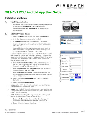
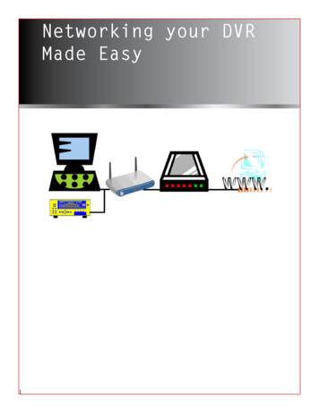
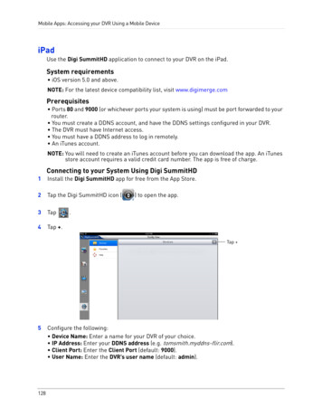
User Manual Embedded Net DVR2.32.3.1Rear Panel DescriptionRear PanelNotice: This picture is for 16nopIndex12345678qrstPhysical InterfaceuDescriptionVideo InputStandard BNC.Audio InputStandard BNC.Video OutputConnect monitor, output video and menu.Audio OutputLocal audio output.Line InAudio line input for voice.USB InterfaceUSB memory disk, USB HDD, USB CD-R/WVGA InterfaceVGA display.Keyboard InterfaceOne is for Dvr pro keyboard, and one is for DVR cascade.RS-232Connect RS-232 devices. Refer to Appendix B for pindefinition.RS-485PTZ connection. Refer to Appendix B for pin definition.UTP Network InterfaceConnect network devices. Refer to Appendix B for pindefinition.External Alarm Input8/16 Alarm in.Relay Output4 Alarm outAC InputUse switch to change AC voltage 220/110V.Page 9 of 104
User Manual Embedded Net DVR2.4External Alarm In/Out ConnectionAlarm input port:G (GND): Conenct the GND of sensor.1 8: Alarm input,open/normal close.supportnormal0: Reserved.Alarm output:1G 4G: 4 relay output.Alarm output connectionPlease note the usage of jumper JJ1. If you use DC, either of connections is OK. We suggestyou to use those DC under 12V, 1A.If you use AC, please open the jumper. There are 4 jumpers (JJ1, JJ2, JJ3 and JJ4) in DVRmain board, corresponding with 4 alarm output. The default is closed.Warning: If you use AC input for relay output, please open the jumpers.Page 10 of 104
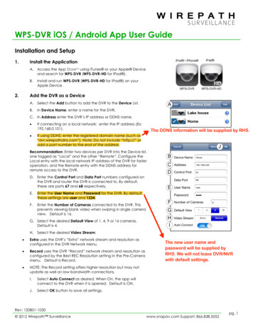
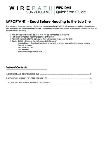
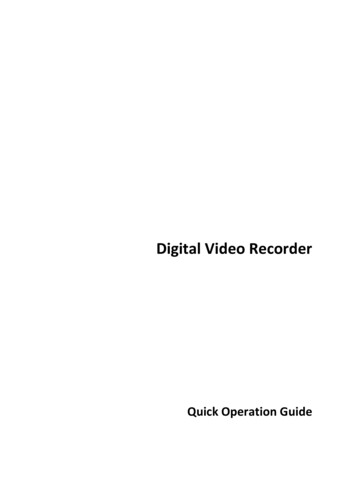
User Manual Embedded Net DVRChapter3 Operational Instructions3.1Front PanelnorIndexTypeName1spqtuDescriptionIR receiver.2StateLamps1-8Show channels 1-8 status. Green means recording; Red meansnetwork transmission; Orange means recording and networktransmission. Lamp twinkle and red means the correspondingHDD has error.3StateLamps9-16Show channels 1-16 status. Green means recording; Redmeans network transmission; Orange means recording andnetwork transmission.4POWERPOWERDevice switch with power indicator lamp. Green means DVRis working; Red means DVR is powered off; No light meansno power is /RxDVR is ready.Green means you can use IR remote control.Red means there is alarm.Green means modem connection and dial-up successful.Twinkle in red means reading or writing HDD.Green means network is OK.Twinkle in green means data is being transmitted.6CompoundKeysMENU1.Switch preview mode into menu;2.Brush control short key【WIPER】.ESCPLAYCancel and back to parent menu.1. Local playback;RECPage 11 of 104
User Manual Embedded Net DVREDIT2. 【AUTO】in PTZ mode.1.PTZ2. 【SHOT】in PTZ mode (adjust preset).1.AIn edit state, delete current cursor character;2. 【IRIS 】 in PTZ control;1.PREVManual record;Select 9 or to enable or disable.1. Enter into PTZ control mode;2. 【IRIS-】in PTZ control.INFOVOIP1. Input switch (number, lower case, upper case andsymbol);2. 【FOCUS 】in PTZ control;3. In preview mode, display or hide the channel status bar.1. Multi screen preview switch;2. Switch menu mode into preview;3. 【FOCUS-】in PTZ control.【ZOOM 】in PTZ control.【ZOOM-】in PTZ control.7InputKeysNumericKeysF1F2Input number, lower case, upper case character and symbols.【LIGHT】in PTZ control.【AUX】in PTZ control.8ControlKeysDirectionKeysComposed of 【Ç】,【È】,【Å】and【Æ】.1.ENTERMenu mode, use【Å】/【Æ】 to select 【Ç】/【È】 toedit;2. PTZ direction control;3. Playback speed control.1. Menu confirmation;2.Select 9 or to enable or disable;3.Pause playback.Page 12 of 104
User Manual Embedded Net DVRPage 13 of 104
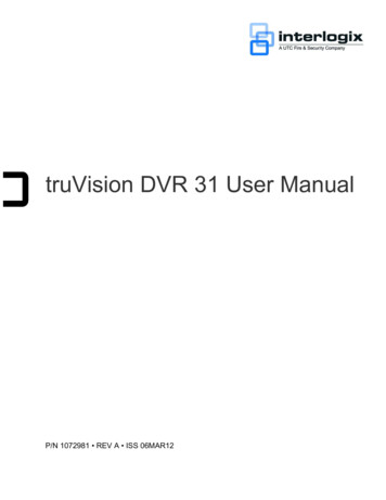
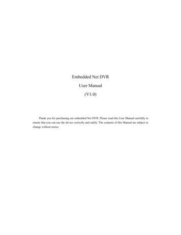
User Manual Embedded Net DVR3.2IR ControllerIndexNameDescription1POWERTurnoff device.2DEVEnable/Disable IR remote control3Numeric KeysSame as numeric keys of front panel.4EDITSame as EDIT key of front panel.5ASame as A key of front panel.6RECSame as REC key of front panel.7PLAYSame as PLAY key of front panel.8INFOSame as INFO key of front panel.9VOIPSame as VOIP key of front panel.10MENUSame as MENU key of front panel.11PREVSame as PREV key of front panel.12Direction KeysENTERSame as direction keys and enter keyof front panel.13PTZSame PTZ key of front panel.Page 14 of 104
User Manual Embedded Net DVR14ESCSame as ESC key of front panel.15Reserved16F1Same as【F1】key of front panel.17Lens controlIRIS, FOCUScontrol.18F2Same as【F2】key of front panel.ZOOMforlensLoading the batteries into the IR controller1. Remove the battery cover.2. Insert the battery. Please take care that the poles ( and -) are correctly positioned.3. Replace the battery cover.Start to use IR controllerPress【DEV】key, input the DVR device ID (default is “88”, can be changed in “Display”menu) and then press【ENTER】key. If the “STATUS” lamp of DVR front panel is turned intogreen, it means you can use IR controller to operate this DVR.Stop using IR controllerWhen IR controller status is on, press【DEV】key again, the “STATUS” lamp will be turnedoff. The IR controller can not control this DVR.Switch the DVR offWhen IR controller status is on, press【POWER】key for several seconds, the DVR will bepowered off.When IR controller can not work normallyz Check batteries poles.z Check the remaining charge in the batteries.z Check IR controller sensor is mask.Please change another IR controller to try again. It the problem is still existed, please contactadministrator.Page 15 of 104
User Manual Embedded Net DVR3.3Menu Description3.3.1 Menu ItemsMenu NameDisplayRecordingAlarmsPTZPreviewFunctionVideo standardBrightnessMenu transparencyUnit nameDevice IDRequire passwordScreen saver timeVGA resolutionDate and TimeOverwrite/Stop recordingResolutionandrecordingparameters setupRecord schedulePreRecord timePostRecord timeAlarm input type (Normal open/Normal close)Alarm response and PTZ linkageAlarm output and schedulePTZ parametersPreset setupSequence setupCruise setupPreview modeSwitch timeEnable/Disable audio previewPreview layoutMenu NameFunctionImageCamera name and position setupAdjust Brightness, Contrast, Hueand SaturationOSD Display mode, position andOSD format setupMask area setupView tampering area and responsesetupVideo signal lossMotion detection sensitivity, areaand response setupNetworkExceptionsRS232UserPasswordDVR IP addressDNS IPMulticast IP addressRemote host IP and portNAS IP and directoryPPPoE username and passwordExceptions typeExceptions responseRS232 parametersAdd or delete userPassword setup or modificationUser rights setupPage 16 of 104
User Manual Embedded Net DVRPowerOffShut down DVRUtilitiesRestore parametersUpgrade firmwareHDD managementClear alarm outputRebootPower offView logSystem informationPage 17 of 104
User Manual Embedded Net DVR3.3.2 Menu OperationHow to enter into menu modezPress【MENU】key to enter into DVR main menu.zPress【PLAY】short key to enter into playback menu.zPerss【REC】short key to enter into manual record menu.zPerss【PTZ】short key to enter into PTZ control interface.Notes: You must input user name and password. The default user name is “admin” andpassword is “12345”.Main Menu DescriptionThe main menu interface is following:There is one small rectanglar frame named “Active Frame”. It can be moved from one icon toanother by using 【Æ】or【Å】key. When the “Active Frame” is located on one icon, you can press【ENTER】key to enter into the secondary menu. For example, move the “Active Frame” to“Image” icon, press 【ENTER】to enter into the secondary menu as following:Page 18 of 104
User Manual Embedded Net DVREach menu contains different kinds of items. There is a small rectangular frame named“Active Frame” which is pointing to the selected item. This “Active Frame” can be moved by【Æ】or【Å】keys. There are such kinds of menu items:1.Check Box: Provide 2 options, “9” means enable and “ ” means disable. You can use【ENTER】or【EDIT】key to switch over.2.List Box: Provide more than 2 options. However, only one of them can be selected. Youcan use【 】and【 】to select one option. For example, on the right side of “SelectCamera”, there is a list box for you to select one camera.3.Edit Box: This is for you to input characters. Press【EDIT】key to enter into edit status,you can input characters as following:a) Press【A】key to select number, upper case, lower case or symbols;b) Use【Æ】and【Å】keys to move cursor;c) Use【EDIT】key to delete the charcter in front of cursor;d) Press【ENTER】or【ESC】to exit edit.4.Button: Excute a special function or enter into next sub-menu. For example, press“Policy” button to enter into sub-menu. Press【Confirm】to save parameters and returnto parent menu. Press【Cancel】button to cancel and return to parent menu. The button inPage 19 of 104
User Manual Embedded Net DVRgrey means it can be operated only after it is enabled.How to exit menuPress【PREV】key to exit menu and return to preview mode.Page 20 of 104
User Manual Embedded Net DVR3.4Character InputIn the menu interface, if you enter into edit status (for example, in the “camera name” editbox), at the bottom of screen, the input status is appeared:Here it means you can press numeric keys to input digital number.Press【A】key to change input methods. You can select “number”, “Uppercase”, “Lowercase”or “Symbol”.UppercaseLowercaseSymbolThere are 24 symbols in all. They are divided into 4 pages, and you can use【0】key to turn overpage.Page 21 of 104
User Manual Embedded Net DVRChapter4 Basic Operation Guide4.1Power onNote: Please make sure the power supply matches DVR and AC cable connectedcorrectly. Before switch DVR on, please connect one monitor with VOUT or VGA interface.Otherwise, you can not see graphic user interface and can not operate.If【POWER】lamp is off, please do as following:Step1: Connect AC cable correctly;Step2: Switch on the power button on the real panel.If【POWER】lamp is in red, just press【POWER】button to start DVR.When DVR is started,【POWER】lamp is in green. On the monitor or VGA display, DSP andHDD initialization process will be shown.The first line represents DSP initialization. If the DSP icon is “ ”, it means that the DSP isinitialized error, please contact administrator at once.The second line represents HDD initialization. Icons of IDE1 master and slaver HDDs, IDE2master and slaver HDDs, etc are displayed. If the HDD icon is “ ”, it means the correspondingHDD is not installed or not detected. If HDD is not detected, please contact administrator.Note: If HDD is not installed or not detected, DVR can beep for alarm. You can enable thealarm option in “Exceptions” menu.Page 22 of 104
User Manual Embedded Net DVR4.2PreviewDVR will enter into preview mode after it is started.On preview screen, you can see date, time, camera name and camera status icon.Set system date and time in “Display” menu, referring to 5.2.9; Change camera name in“Image” menu, referring to 5.3.2.In the screen, it will display record and alarm status of each camera. These two kinds ofstatus will switch over automatically.Press【A】key to display or hide the camera status bar.Record status of camera is as follows:IconIcon ColorStatus DescriptionWhiteNo video signalYellowVdieo inputPinkManual recordingGreenReal time recordingBlueMotion detect recordingRedExternal alarm recordingPage 23 of 104
User Manual Embedded Net DVRAlarm status of camera is as follows:IconIcon ColorStatus DescriptionWhiteVideo signal lostYellowView tampering alarmPinkMotion&External alarmGreenNo alarmBlueMotion alarmRedExternal alarmPress numeric keys to switch over individual camera preview. If DVR has less than 10channels, press one numeric key to switch corresponding channel. For example, press【2】key topreview 2nd camera. If DVR has 10 or more than 10 channels, press two numeric keys toswitch corresponding channel. For example, press 【0】【2】to preview 2nd camera; and press【1】【2】keys to preview 12th camera.Press【EDIT】key to manual cycle preview. You can set the auto preview mode in “Preview”menu, referring to 5.11.Press【PREV】key to switch multi-screen perview.Page 24 of 104
User Manual Embedded Net DVR4.3User name and passwordNote: When DVR is delivered from factory, there is only one default administratornamed “admin”, and password is “12345”. The administrator’s name can not be modified,while the password can be modified. The administrator can create 15 users and define theiruser rights.LoginLogin dialog is following:Use【Ç】【/ È】keys to select one user, perss【Æ】key to enter into “Password” edit box, inputcorresponding password, press【ENTER】key to exit edit box. The “Active Frame” will be movedto “Confirm” button. Press【ENTER】key to enter into main menu. If there is beeper alarm, itmeans the user name and password are not matched. After three error times, DVR will enter intopreview mdoe.Modify passwordFor those users created by admin, they can modify their password as following:Step1: Enter into main menuPress【MENU】key, in the login dialog, select your user name, input the correct password, youcan enter into the main menu.Page 25 of 104
User Manual Embedded Net DVRSetp 2: Enter into password modification menuMove the “Active Frame” to “Password” icon by using【Æ】/【Å】keys. Press【ENTER】key to enter into following password menu:Step 3: Input new passwordPress【EDIT】key to enter into edit box. You can use numeric keys to input new password.The password can be null. It also can be 16 numerals. Press【ENTER】to exit edit box, and move to“Verify” item to input the verify password.Note: In edit box, use 【Æ】【/ Å】to move cursor and【EDIT】key to delete the numeralin front of the cursor.Page 26 of 104
User Manual Embedded Net DVRStep 4: Modify password successfullyMove the “Active Frame” to “Confirm” button, press【ENTER】key. If the password ismodified successfully, you will get the main menu. Or an error dialog will be pop up. You canrepeat step 3 to modify again.4.4PTZ ControlNote: The user must have the “PTZ control” right.PTZ control interfaceIn preview mode, press【PTZ】key, in the login dialog, select one user name and input thecorrect password, you can enter into PTZ control interface.In menu mode, press【PTZ】key, you can enter into PTZ control interface directly.There is “PTZ Control” prompt in the PTZ control interface. The displayed camera namemeans which channel’s PTZ is under control. For example, “Camera 01” means you arecontrolling the 1st camera PTZ.Select channelIn PTZ control mode, you can press numeric keys to select channel. If DVR has less than 10channels, press one numeric key to select. For example, press【2】key to selct 2nd camera PTZ. IfDVR has 10 or more than 10 channels, you must press two numeric keys to select. For【2】to select 12th camera PTZ.example, press【0】【2】to select 2nd camera PTZ, and press【1】After you select the camera PTZ, you can use the short keys to control PTZ.Page 27 of 104
User Manual Embedded Net DVRPTZ control keys descriptionDirection control keys: 【 】,【 】,【 】,【 】;ZOOM control keys:【ZOOM 】,【ZOOM-】;FOCUS control keys:【FOCUS 】,【FOCUS-】;IRIS control keys:【IRIS 】,【IRIS-】;Adjust preset keys:【REC/SHOT】;Auto control key:【PLAY/AUTO】;Wiper control key:【WIPER/MENU】;Light control key:【LIGHT/F1】;Auxiliary device control key:【AUX/F2】Adjust preset descriptionIn PTZ control mode, press【REC/SHOT】key, and press the preset number (three numerickeys), DVR will adjust the corresponding preset number. Repeat pressing【REC/SHOT】key, andpress the preset number, DVR will adjust that preset number.When you exit PTZ control mode, the camera will stay at the current position.Note: The PTZ preset number is set already. Please refer to PTZ menu for preset setup. V1.4firmware can support 128 preset numbers at most.Start/Stop auto in PTZ control modeIn PTZ control mode, press 【 PLAY/AUTO 】 key to start PTZ auto function. Press【PLAY/AUTO】key again to stop.When PTZ is in auto mode, if you exit PTZ control mode, PTZ will continue autofunction.You must enter into PTZ control mode again, and press【PLAY/AUTO】key to stop.Exit PTZ contrl modePress【ESC】or【ENTER】to exit and return preview mode.Page 28 of 104
User Manual Embedded Ne
Please ask the specialist to disassembly the DVR and install HDD. Installation instrument One cross screw driver. HDD installation 1. Open the DVR box. 2. If you want to install 2 HDD for one IDE interface, please set master and slaver HDD. 3. Take off the HDD mounting plate. 4. Place the HDD on the mounting plate and fix it with screw. 5.