Transcription
PowerFlex 700LActive Converter Power ModuleUSER MANUALFirmware Version 3.xxx
Important UserInformationSolid state equipment has operational characteristics differing from those ofelectromechanical equipment. Safety Guidelines for the Application, Installation andMaintenance of Solid State Controls (Publication SGI-1.1 available from your localRockwell Automation sales office or online at http://www.rockwellautomation.com/literature) describes some important differences between solid state equipment andhard-wired electromechanical devices. Because of this difference, and also because ofthe wide variety of uses for solid state equipment, all persons responsible for applyingthis equipment must satisfy themselves that each intended application of thisequipment is acceptable.In no event will Rockwell Automation, Inc. be responsible or liable for indirect orconsequential damages resulting from the use or application of this equipment.The examples and diagrams in this manual are included solely for illustrativepurposes. Because of the many variables and requirements associated with anyparticular installation, Rockwell Automation, Inc. cannot assume responsibility orliability for actual use based on the examples and diagrams.No patent liability is assumed by Rockwell Automation, Inc. with respect to use ofinformation, circuits, equipment, or software described in this manual.Reproduction of the contents of this manual, in whole or in part, without writtenpermission of Rockwell Automation, Inc. is prohibited.Throughout this manual, when necessary we use notes to make you aware of safetyconsiderations.!WARNING: Identifies information about practices orcircumstances that can cause an explosion in a hazardousenvironment, which may lead to personal injury or death, propertydamage, or economic loss.Important: Identifies information that is critical for successful application andunderstanding of the product.!ATTENTION: Identifies information about practices orcircumstances that can lead to personal injury or death, propertydamage, or economic loss. Attentions help you identify a hazard,avoid a hazard, and recognize the consequences.Shock Hazard labels may be located on or inside the equipment(e.g., drive or motor) to alert people that dangerous voltage may bepresent.Burn Hazard labels may be located on or inside the equipment(e.g., drive or motor) to alert people that surfaces may be atdangerous temperatures.Allen-Bradley, PowerFlex, DriveExplorer, DriveExecutive, and DPI are either registered trademarks or trademarks of Rockwell Automation, Inc.PowerFlex 700L Active Converter Power Module User Manual
Summary of ChangesThe information below summarizes the changes resulting from the firmwarev3.001 upgrade to this manual since its last release (June, 2006):Description of New or Updated InformationTo all pages, added a new footer containing:Page(s)ThroughoutManual Publication description (1st line). Publication number hyperlink underlined in blue (2nd line) linking to the date of thepublication on the back cover.The back cover publication date line hyperlinks to the newest version of the publicationon Rockwell Automation’s Literature Library web site.Added new information about the Active Converter operating as a Coupled unit (DPI1-6SLAVE) or as a Stand Alone unit (DPI MASTER).Changed the following for Parameter 051 - [Option Select]:3-6 Bit 6 changed from “Reserved” to “VC Inverter.” Bit 7 changed from “Reserved” to “Prechg Cntrl.” The default changed from “xxxx xxxx xx00 0001” to “xxxx xxxx 0000 0001.”Added new Parameter 105 - [Regen I Lmt].Changed Parameter 153 - [CML Bandwidth] maximum value from “3000 Rad/sec” to“4000 Rad/sec.”Changed the description for Parameter 157 - [PF Bandwidth] to include that it should beused only when unbalanced voltage compensation is enabled in Parameter 051 [Option Select].Changed Parameter 162 - [Capacitance] maximum value from “32767 µF” to “65535 µF.”Added new Parameter 170 - [Bus Capacitance].Added new Bit 11 (High DC Link) to Parameter 214 - [Start Inhibit].Changed Parameter 238 - [Fault Config] default from “xxxx xxx1 1110 1100” to“xxxx xxx1 0110 1100.”Added two new parameter groups which are only displayed and available in theCommunication File when the Converter is operated as a Stand Alone unit: Masks and Owners Group– Parameter 340 - [Logic Mask]– Parameter 341 - [Start Mask]– Parameter 342 - [Fault Clr Mask]– Parameter 343 - [Stop Owner]– Parameter 344 - [Start Owner]– Parameter 345 - [Fault Clr Owner] Security Group– Parameter 346 - [Port Mask Act]– Parameter 347 - [Write Mask Cfg]– Parameter 348 - [Write Mask Act]– Parameter 349 - [Logic Mask Act]Added the following new fault codes: 3-93-113-113-123-123-143-153-184-370 – FiltCap Contactr71 – Port 1 Adapter72 – Port 2 Adapter73 – Port 3 Adapter74 – Port 4 Adapter75 – Port 5 Adapter76 – Port 6 Adapter81 – Port 1 DPI Loss82 – Port 2 DPI Loss83 – Port 3 DPI Loss84 – Port 4 DPI Loss85 – Port 5 DPI Loss86 – Port 6 DPI LossPowerFlex 700L Active Converter Power Module User ManualPublication PFLEX-UM002D-EN-P
soc-iiSummary of ChangesPowerFlex 700L Active Converter Power Module User ManualPublication PFLEX-UM002D-EN-P
Table of ContentsPrefaceOverviewWho Should Use this Manual? . . . . . . . . . . . . . . . . . . . . . . . . . . . . . . . . . . . . . . . . . . . . .What Is Not in this Manual . . . . . . . . . . . . . . . . . . . . . . . . . . . . . . . . . . . . . . . . . . . . . . . .LPM20 Liquid-Cooled AC Drive Installation . . . . . . . . . . . . . . . . . . . . . . . . . . . . . . .PowerFlex 700L Liquid-Cooled AC Drive Information . . . . . . . . . . . . . . . . . . . . . . .PowerFlex 700 Vector Control Information (standard) . . . . . . . . . . . . . . . . . . . . . . . .PowerFlex 700S Phase II Control Information (optional) . . . . . . . . . . . . . . . . . . . . . .Reference Materials . . . . . . . . . . . . . . . . . . . . . . . . . . . . . . . . . . . . . . . . . . . . . . . . . . . . .Publications . . . . . . . . . . . . . . . . . . . . . . . . . . . . . . . . . . . . . . . . . . . . . . . . . . . . . . . . . .Allen-Bradley Drives Technical Support . . . . . . . . . . . . . . . . . . . . . . . . . . . . . . . . . . .Manual Conventions . . . . . . . . . . . . . . . . . . . . . . . . . . . . . . . . . . . . . . . . . . . . . . . . . . . . .General Precautions . . . . . . . . . . . . . . . . . . . . . . . . . . . . . . . . . . . . . . . . . . . . . . . . . . . . .Chapter 1Installation/WiringRemoving the Active Converter Power Module Covers . . . . . . . . . . . . . . . . . . . . . . . . .Removing the Active Converter Control Cassette . . . . . . . . . . . . . . . . . . . . . . . . . . . . . .Frame 2 and 3A Drives . . . . . . . . . . . . . . . . . . . . . . . . . . . . . . . . . . . . . . . . . . . . . . . . .Frame 3B Drives . . . . . . . . . . . . . . . . . . . . . . . . . . . . . . . . . . . . . . . . . . . . . . . . . . . . . .Wiring the Active Converter Control Cassette I/O Terminals . . . . . . . . . . . . . . . . . . . . .I/O Terminal Blocks . . . . . . . . . . . . . . . . . . . . . . . . . . . . . . . . . . . . . . . . . . . . . . . . . . .Using the Active Converter as a Coupled Unit vs. Standalone Unit . . . . . . . . . . . . . . .Setting the DPI MASTER/SLAVE Switch (SW1) . . . . . . . . . . . . . . . . . . . . . . . . . . . .Connecting an Active Converter Power Module to an Inverter Power Module . . . . . . . .Frame 2 and 3A Drives . . . . . . . . . . . . . . . . . . . . . . . . . . . . . . . . . . . . . . . . . . . . . . . . .Frame 3B Drives . . . . . . . . . . . . . . . . . . . . . . . . . . . . . . . . . . . . . . . . . . . . . . . . . . . . . .Chapter -51-61-81-81-81-8Start UpEstablishing Communication as a Coupled Unit . . . . . . . . . . . . . . . . . . . . . . . . . . . . . . . 2-1Accessing Active Converter Power Module Parameters. . . . . . . . . . . . . . . . . . . . . . . . 2-1Verifying Feedback Parameters. . . . . . . . . . . . . . . . . . . . . . . . . . . . . . . . . . . . . . . . . . . 2-4Exchanging Data . . . . . . . . . . . . . . . . . . . . . . . . . . . . . . . . . . . . . . . . . . . . . . . . . . . . . . 2-5CIP Messages . . . . . . . . . . . . . . . . . . . . . . . . . . . . . . . . . . . . . . . . . . . . . . . . . . . . . . . . 2-7Establishing Communication as a Stand Alone Unit . . . . . . . . . . . . . . . . . . . . . . . . . . . . 2-8Accessing Active Converter Power Module Parameters. . . . . . . . . . . . . . . . . . . . . . . . 2-8Verifying Feedback Parameters. . . . . . . . . . . . . . . . . . . . . . . . . . . . . . . . . . . . . . . . . . . 2-9Converter Sequencing . . . . . . . . . . . . . . . . . . . . . . . . . . . . . . . . . . . . . . . . . . . . . . . . . . . 2-12Run On Start . . . . . . . . . . . . . . . . . . . . . . . . . . . . . . . . . . . . . . . . . . . . . . . . . . . . . . . . 2-12Run On PwrUp . . . . . . . . . . . . . . . . . . . . . . . . . . . . . . . . . . . . . . . . . . . . . . . . . . . . . . 2-13Manual Cntrl . . . . . . . . . . . . . . . . . . . . . . . . . . . . . . . . . . . . . . . . . . . . . . . . . . . . . . . . 2-13Start Inhibit . . . . . . . . . . . . . . . . . . . . . . . . . . . . . . . . . . . . . . . . . . . . . . . . . . . . . . . . . 2-13Sequencing Precautions. . . . . . . . . . . . . . . . . . . . . . . . . . . . . . . . . . . . . . . . . . . . . . . . 2-13Control Setup . . . . . . . . . . . . . . . . . . . . . . . . . . . . . . . . . . . . . . . . . . . . . . . . . . . . . . . . . 2-14Current Limits . . . . . . . . . . . . . . . . . . . . . . . . . . . . . . . . . . . . . . . . . . . . . . . . . . . . . . . 2-14Line Voltage Limits . . . . . . . . . . . . . . . . . . . . . . . . . . . . . . . . . . . . . . . . . . . . . . . . . . . 2-14Frequency Limits. . . . . . . . . . . . . . . . . . . . . . . . . . . . . . . . . . . . . . . . . . . . . . . . . . . . . 2-15Voltage Loop . . . . . . . . . . . . . . . . . . . . . . . . . . . . . . . . . . . . . . . . . . . . . . . . . . . . . . . . 2-15Current Loop . . . . . . . . . . . . . . . . . . . . . . . . . . . . . . . . . . . . . . . . . . . . . . . . . . . . . . . . 2-16PWM Carrier Synchronization . . . . . . . . . . . . . . . . . . . . . . . . . . . . . . . . . . . . . . . . . . 2-16PowerFlex 700L Active Converter Power Module User ManualPublication PFLEX-UM002D-EN-P
iiTable of ContentsConverter Faults. . . . . . . . . . . . . . . . . . . . . . . . . . . . . . . . . . . . . . . . . . . . . . . . . . . . . . . .Converter Faults as a Coupled Unit (DPI SLAVE) . . . . . . . . . . . . . . . . . . . . . . . . . . .Displaying the Fault Text. . . . . . . . . . . . . . . . . . . . . . . . . . . . . . . . . . . . . . . . . . . . . . .Resetting Converter Faults. . . . . . . . . . . . . . . . . . . . . . . . . . . . . . . . . . . . . . . . . . . . . .Chapter 32-172-172-172-18Programming and ParametersAbout Parameters. . . . . . . . . . . . . . . . . . . . . . . . . . . . . . . . . . . . . . . . . . . . . . . . . . . . . . . . 3-1How Parameters are Organized . . . . . . . . . . . . . . . . . . . . . . . . . . . . . . . . . . . . . . . . . . . . . 3-2File-Group-Parameter Order . . . . . . . . . . . . . . . . . . . . . . . . . . . . . . . . . . . . . . . . . . . . . 3-2Numbered List View . . . . . . . . . . . . . . . . . . . . . . . . . . . . . . . . . . . . . . . . . . . . . . . . . . . 3-3Monitor File . . . . . . . . . . . . . . . . . . . . . . . . . . . . . . . . . . . . . . . . . . . . . . . . . . . . . . . . . . . 3-4Command File . . . . . . . . . . . . . . . . . . . . . . . . . . . . . . . . . . . . . . . . . . . . . . . . . . . . . . . . . 3-6Limit Config File . . . . . . . . . . . . . . . . . . . . . . . . . . . . . . . . . . . . . . . . . . . . . . . . . . . . . . . 3-9Dynamic Control File . . . . . . . . . . . . . . . . . . . . . . . . . . . . . . . . . . . . . . . . . . . . . . . . . . . 3-11Utility File . . . . . . . . . . . . . . . . . . . . . . . . . . . . . . . . . . . . . . . . . . . . . . . . . . . . . . . . . . . . 3-13Communication File . . . . . . . . . . . . . . . . . . . . . . . . . . . . . . . . . . . . . . . . . . . . . . . . . . . . 3-17Inputs & Outputs File . . . . . . . . . . . . . . . . . . . . . . . . . . . . . . . . . . . . . . . . . . . . . . . . . . . 3-20Parameter Cross Reference – by Name . . . . . . . . . . . . . . . . . . . . . . . . . . . . . . . . . . . . . 3-22Parameter Cross Reference – by Number . . . . . . . . . . . . . . . . . . . . . . . . . . . . . . . . . . . . 3-23Chapter 4TroubleshootingFaults and Alarms . . . . . . . . . . . . . . . . . . . . . . . . . . . . . . . . . . . . . . . . . . . . . . . . . . . . . . .Manually Clearing Faults. . . . . . . . . . . . . . . . . . . . . . . . . . . . . . . . . . . . . . . . . . . . . . . . . .Fault Descriptions . . . . . . . . . . . . . . . . . . . . . . . . . . . . . . . . . . . . . . . . . . . . . . . . . . . . . . .Clearing Alarms. . . . . . . . . . . . . . . . . . . . . . . . . . . . . . . . . . . . . . . . . . . . . . . . . . . . . . . . .Alarm Descriptions . . . . . . . . . . . . . . . . . . . . . . . . . . . . . . . . . . . . . . . . . . . . . . . . . . . . . .IndexPowerFlex 700L Active Converter Power Module User ManualPublication PFLEX-UM002D-EN-P4-14-14-14-44-4
PrefaceOverviewThe purpose of this manual is to provide you with the basic informationneeded to wire and operate the PowerFlex 700 Active Converter PowerModule.For information on .Who Should Use this Manual?What Is Not in this ManualReference MaterialsManual ConventionsGeneral PrecautionsSee page .P-1P-1P-2P-2P-3Who Should Use thisManual?This manual is intended for qualified personnel. You must be able to wireand operate Adjustable Frequency AC Drive devices. In addition, you musthave an understanding of the parameter settings and functions.What Is Not in this ManualThis manual is designed to provide only basic active converter I/O wiring,start-up, programming, and other related information.LPM20 Liquid-Cooled AC Drive InstallationFor information on installing LPM20 Liquid-Cooled AC drives, please referto LPM20 Liquid-Cooled Adjustable Frequency AC Drive InstallationManual — (Publication No. 20N-IN001 ).PowerFlex 700L Liquid-Cooled AC Drive InformationFor information on installing PowerFlex 700L Liquid-Cooled AC drives,please refer to PowerFlex 700L Liquid-Cooled Adjustable Frequency ACDrive User Manual — (Publication No. 20L-UM001 ).PowerFlex 700 Vector Control Information (standard)For PowerFlex Liquid-Cooled AC drives equipped with standard PowerFlex700 Vector Control, please refer to the PowerFlex 700 Adjustable FrequencyAC Drive User Manual — Series B (Publication No. 20B-UM002 ) whichprovides I/O wiring, start-up, programming, and vector control encoderinformation.PowerFlex 700L Active Converter Power Module User ManualPublication PFLEX-UM002D-EN-P
P-2OverviewPowerFlex 700S Phase II Control Information (optional)For PowerFlex Liquid-Cooled AC drives equipped with optional PowerFlex700S Phase II Control, please refer to the PowerFlex 700S HighPerformance AC Drive — Phase II Control User Manual (Publication No.20D-UM006 ) which provides I/O wiring, start-up, programming, andother related information.Reference MaterialsPublicationsPublications can be obtained online athttp://www.rockwellautomation.com/literature.The following manuals are recommended for general drive information:TitleWiring and Grounding Guidelines for Pulse Width Modulated (PWM) AC DrivesPreventive Maintenance of Industrial Control and Drive System EquipmentSafety Guidelines for the Application, Installation, and Maintenance of Solid StateControlA Global Reference Guide for Reading Schematic DiagramsGuarding Against Electrostatic DamagePublicationDRIVES-IN001 DRIVES-TD001 SGI-1.10100-2.108000-4.5.2Allen-Bradley Drives Technical SupportOnline: www.ab.com/support/abdrivesManual Conventions In this manual we refer also to the PowerFlex 700 Active ConverterPower Module as Active Converter, converter or PowerFlex 700AC. To help differentiate parameter names and LCD display text from othertext, the following conventions will be used:– Parameter Names will appear in [brackets].For example: [DC Bus Voltage].– Display Text will appear in “quotes.” For example: “Enabled.” The following words are used throughout the manual to describe an action:WordCanCannotMayMustShallShouldShould NotPowerFlex 700L Active Converter Power Module User ManualPublication PFLEX-UM002D-EN-PMeaningPossible, able to do somethingNot possible, not able to do somethingPermitted, allowedUnavoidable, you must do thisRequired and necessaryRecommendedNot recommended
OverviewGeneral Precautions!!!!P-3ATTENTION: This drive contains ESD (Electrostatic Discharge)sensitive parts and assemblies. Static control precautions arerequired when installing, testing, servicing or repairing thisassembly. Component damage may result if ESD controlprocedures are not followed. If you are not familiar with staticcontrol procedures, refer to Allen-Bradley publication 8000-4.5.2,“Guarding Against Electrostatic Damage” or any other applicableESD protection handbook.ATTENTION: An incorrectly applied or installed drive canresult in component damage or a reduction in product life. Wiringor application errors, such as, undersizing the motor, incorrect orinadequate AC supply, or excessive ambient temperatures mayresult in malfunction of the system.ATTENTION: Only qualified personnel familiar with adjustablefrequency AC drives and associated machinery should plan orimplement the installation, start-up, and subsequent maintenanceof the system. Failure to comply may result in personal injury and/or equipment damage.ATTENTION: To avoid an electric shock hazard, verify that thevoltage on the bus capacitors has discharged before performingany work on the drive. After removing power to the drive, wait 5minutes for the bus capacitors to discharge. Refer to the: LPM20 Liquid-Cooled Adjustable Frequency AC DriveInstallation Manual (Publication No. 20N-IN001 ),Figure 4.2, and measure the DC bus voltage at the locationsshown. The voltage must be zero. PowerFlex 700L Liquid-Cooled Adjustable Frequency ACDrive User Manual (Publication No. 20L-UM001 ), andmeasure the DC bus voltage at the DC POSITIVE and DCNEGATIVE test point sockets located on the front of the powermodule. The voltage must be zero.!ATTENTION: Risk of injury or equipment damage exists. DPIhost products must not be directly connected together via 1202cables. Unpredictable behavior can result if two or more devicesare connected in this manner.PowerFlex 700L Active Converter Power Module User ManualPublication PFLEX-UM002D-EN-P
P-4OverviewNotes:PowerFlex 700L Active Converter Power Module User ManualPublication PFLEX-UM002D-EN-P
Chapter1Installation/WiringThis chapter provides information on installing and wiring the PowerFlex700 Active Converter Power Module.For information on Removing the Active Converter Power Module CoversRemoving the Active Converter Control CassetteWiring the Active Converter Control Cassette I/O TerminalsSee page 1-21-21-4Most start-up difficulties are the result of incorrect wiring. Every precautionmust be taken to assure that the wiring is done as instructed. All items mustbe read and understood before the actual installation begins.!ATTENTION: The following information is merely a guide forproper installation. Rockwell Automation, Inc. cannot assumeresponsibility for the compliance or the noncompliance to anycode, national, local or otherwise for the proper installation ofthis drive or associated equipment. A hazard of personal injuryand/or equipment damage exists if codes are ignored duringinstallation.PowerFlex 700L Active Converter Power Module User ManualPublication PFLEX-UM002D-EN-P
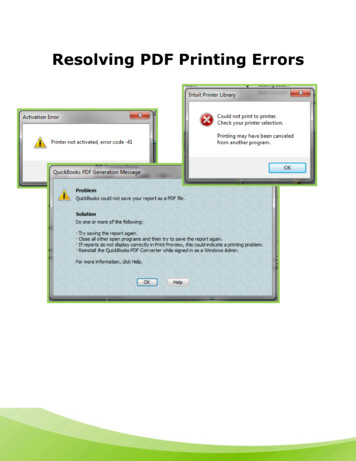
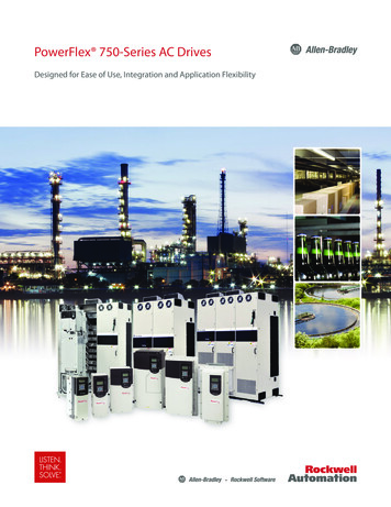
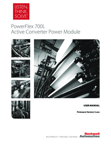
1-2Installation/WiringRemoving the ActiveConverter Power ModuleCoversAll converter covers, regardless of drive frame size, are similarly removedby unfastening the screws. A Frame 3B converter is shown as an example.PORTMODNET ANET B(4 Screws)PowerFlex 700LLiquid-Cooled AC DriveFrame 3B Converter shownRemoving the ActiveConverter Control CassetteRegenerative PowerFlex 700L Liquid-Cooled AC drives use an ActiveConverter Power Module equipped with a converter control cassette.Frame 2 and 3A DrivesPowerFlex 700L Liquid-Cooled Frame 2 and 3A drives combine the ActiveConverter and Inverter into a single Power Module. Figure 1.1 shows thelocation and removal of the Active Converter control cassette to access itsterminal blocks for control wiring. (The Inverter control cassette is locatedjust above the Active Converter control cassette.)PowerFlex 700L Active Converter Power Module User ManualPublication PFLEX-UM002D-EN-P
Installation/Wiring1-3Figure 1.1 Removing the Frame 2 and 3A Active Converter Control CassetteDetailPin 140-PinRibbon CableSynchronization Cable(For use with 700S Phase II Control only)Internal DPI CableP1Synchronization Cable(For use with 700 Vector Control only)SHLDSHLDP2CommunicationsAdapter OptionFrame 3B DrivesFigure 1.2 shows the location and removal of the Active Converter controlcassette to access its terminal blocks for control wiring. Frame 3B driveshave separate Converter Power Modules and Inverter Power Modules.Figure 1.2 Removing the Frame 3B Active Converter Control CassetteSynchronization Cable(For use with coupled Inverter PowerModules with 700S Phase II Control only)Internal DPI CableSynchronization Cable(For use with coupled Inverter PowerModules with 700 Vector Control only)40-PinRibbon CablePin 1P1P2DetailPowerFlex 700L Active Converter Power Module User ManualPublication PFLEX-UM002D-EN-P
1-4Installation/WiringWiring the Active ConverterControl Cassette I/OTerminalsAll wiring should be installed in conformance with the applicable local,national, and international codes (e.g., NEC/CEC). Signal wiring, controlwiring, and power wiring must be routed in separate conduits to preventinterference with drive operation. Use grommets, when hubs are notprovided, to guard against wire chafing.!ATTENTION: Do not route signal and control wiring withpower wiring in the same conduit. This can cause interferencewith drive operation. Failure to observe this precaution couldresult in damage to, or destruction of, the equipment.Important points to remember about I/O wiring: Use Copper wire only. Wire gauge requirements and recommendationsare based on 75 degrees C. Do not reduce wire gauge when using highertemperature wire. Wire with an insulation rating of 600V or greater is recommended. Control and signal wires should be separated from power wires by atleast 0.3 meters (1 foot).Important: I/O terminals labeled “(–)” or “Common” are not referenced toearth ground and are designed to greatly reduce common modeinterference. Grounding these terminals can cause signal noise.Terminal blocks P1 and P2, shown in Figure 1.1 and Figure 1.3, containconnection points for all inputs, outputs, and power connections to theActive Converter control cassette.1. Remove the terminal block plug from the socket, and make connections.2. Reinstall the terminal block plug when wiring is complete. The terminalblocks have keys, which make it difficult to insert a terminal block pluginto the wrong socket.PowerFlex 700L Active Converter Power Module User ManualPublication PFLEX-UM002D-EN-P
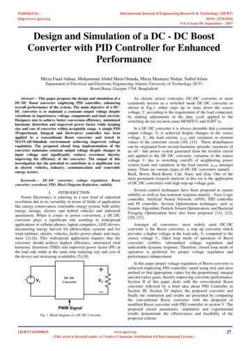
Installation/Wiring1-5Figure 1.3 Active Converter Control Cassette I/O Terminal, Cable Connection, andDPI SLAVE/MASTER Switch SW1 LocationsJ1 40-PinRibbon CableHeaderActive ConverterControl PCB AssemblySW1J2 30-PinRibbon CableHeaderONJ9 SynchronizationCable Header(700S Ph. II Control only)ONDPI SLAVE OFFDPI MASTER ONJ4 Internal DPICable HeaderP1 I/O Terminals(see Table 1.B forterminal descriptions)SW1123456789101112131415P1-7 and P1-8SynchronizationCable Connection(700 Vector Control only)7654321P1-13 and P1-14Factory-InstalledGate Kill JumperP2 I/O Terminals(see Table 1.C forterminal descriptions)Voltage FeedbackResistor PCB AssemblyI/O Terminal BlocksTable 1.A Active Converter Control Board I/O Terminal Block SpecificationsNameDescriptionI/O BlocksSignal and powerconnections(1)Wire Size Range (1)MaximumMinimum1.5 mm20.14 mm2(16 AWG)(28 AWG)Maximum0.25 N-m(2.2 lb.-in.)TorqueRecommended0.22 N-m(1.9 lb.-in.)Maximum/minimum that the terminal block will accept - these are not recommendations.PowerFlex 700L Active Converter Power Module User ManualPublication PFLEX-UM002D-EN-P
1-6Installation/WiringTable 1.B Active Converter Control PCB Assembly P1 Terminal m Out Comm Out SOC Out SOC Out Comm In Comm In SOC In SOC In Aux Out N.O.Aux Out CommonAnalog In SignalAnalog In CommonGate Enable24 VdcAux InputTable 1.C Voltage Feedback Resistor PCB Assembly P2 Terminal DescriptionsPin741DescriptionL3L2L1Specific pins on P1 and P2 terminals require control wiring connections tothe Input Filter Bay. For wiring information, please refer to the PowerFlex700L Liquid-Cooled Adjustable Frequency AC Drive User Manual(Publication No. 20L-UM001 ).Using the Active Converter as a Coupled Unit vs. Standalone UnitFrame 3B converter power structures may be ordered as a unit Coupled toan inverter (DPI SLAVE), or as a Stand Alone unit (DPI MASTER). Frame2 and Frame 3A power structures are always wired for the converter to be aCoupled unit.CoupledFigure 1.4 shows the Active Converter wired to operate as a Coupled unit(DPI SLAVE). In this configuration, the Converter is connected to aPowerFlex 700L Inverter through DPI Port 6. When configured for "Run OnStart," the Converter is able to start and stop automatically as the Inverter isstarted and stopped.PowerFlex 700L Active Converter Power Module User ManualPublication PFLEX-UM002D-EN-P
Installation/Wiring1-7Figure 1.4 Active Converter Operating as a Coupled Unit (DPI SLAVE)Frame 3A with Converter as aCoupled Unit (DPI SLAVE)InverterConverterFrame 3B with Converter as aCoupled Unit (DPI nalComputer1203-USB or 1203-SSSSerial Converter1203-USB or 1203-SSSSerial ConverterStand AloneFigure 1.5 shows the Active Converter wired to operate as a Stand Aloneunit (DPI MASTER). In this configuration, the Converter may have a HIMor any PowerFlex 7-Class network communication adapter (20-COMM-x)connected. This may be preferred when the converter is to supply the DCbus for a set of common bus inverters. When configured for "Run On Start,"the precharge bypass contactor may be configured to close when the poweris turned on and the DC Bus voltage is stable (see Parameter 51 - [OptionSelect]). The Converter starts and stops with commands from the HIM, the1203-USB or 1203-SSS serial converter, or a 20-COMM-x networkcommunication adapter.Figure 1.5 Active Converter Operating as a Stand Alone Unit (DPI MASTER)Frame 3B with Converter as aStand Alone Unit (DPI OMM-xPersonalComputer181046-C011203-USB or 1203-SSSSerial ConverterPowerFlex 700L Active Converter Power Module User ManualPublication PFLEX-UM002D-EN-P
1-8Installation/WiringThe Frame 3B Active Converter power module is ordered as a Stand Aloneunit (DPI SLAVE) by specifying equipment type P in the catalog number(refer to the catalog number explanation in the PowerFlex 700L UserManual).The Stand Alone (DPI SLAVE) Active Converter is supported with ActiveConverter firmware revision 3.001 (or higher).To operate the Frame 3B Active Converter as a Stand Alone unit (DPISLAVE) the DPI MASTER/SLAVE switch (SW1) on the Active Convertercontrol board must be properly set. Refer to Setting the DPI MASTER/SLAVE Switch (SW1) below for details.Setting the DPI MASTER/SLAVE Switch (SW1)Active Converters with version 2.006 (or lower) firmware are alwaysoperated as a peripheral on DPI port 6. In this case, switch SW1 on theActive Converter control PCB assembly (Figure 1.3) is set to OFF (DPISLAVE). Do not use the ON setting. For Active Converters with version3.001 (or higher) firmware, switch SW1 is used to select between converteroperation as a Coupled unit (DPI SLAVE position) or as a Stand Alone unit(DPI MASTER position).Connecting an ActiveConverter Power Module toan Inverter Power ModuleFrame 2 and 3A DrivesCoupling a Frame 2 or 3A Power Module is achieved by using two cables: aDPI cable and a control synchronization cable. These cables are factoryinstalled.Frame 3B DrivesCoupling a Frame 3B Active Converter Power Module to a Frame 3BInverter Power Module is achieved by using two cables: a DPI cable and acontrol synchronization cable. For the Complete Drive equipment type,these cables are factory installed. When Power Modules are purchasedseparately, these cables are user installed. For information regarding thesecables and their installation, please refer to the PowerFlex 700LLiquid-Cooled Adjustable Frequency AC Drive User Manual (PublicationNo. 20L-UM001 ), Chapter 3 in the “Synchronization Connections forFrame B” section.PowerFlex 700L Active Converter Power Module User ManualPublication PFLEX-UM002D-EN-P
Chapter2Start UpThe start-up procedure built into the HIM addresses only the start up of theinverter. This chapter describes how to start up the PowerFlex 700 ActiveConverter Power Module.For information on Establishing Communication as a Coupled UnitEstablishing Communication as a Stand Alone UnitConverter SequencingControl SetupConverter FaultsEstablishingCommunication as aCoupled UnitSee page 2-12-82-122-142-17When the Converter is set to operate as a Coupled unit (DPI SLAVE), thefirst step after turning on power is to verify that you are able tocommunicate with the unit and that it properly displays selected data.Data is exchanged between the Inverter Power Module and ActiveConverter Power Module to pass control and status information.An example is given for how to communicate with the Acti
environment, which may lead to personal injury or death, property damage, or economic loss.! . used only when unbalanced voltage compensation is enabled in Parameter 051 - 3-11 Changed Parameter 162 - [Capacitance] maximum value from "32767 µF" to "65535 µF." 3-12 . Power Module as Active Converter, converter or PowerFlex 700AC. .