Transcription
User ManualPowerFlex 525 DeviceNet AdapterCatalog Number: 25-COMM-D
Important User InformationSolid-state equipment has operational characteristics differing from those of electromechanical equipment. SafetyGuidelines for the Application, Installation and Maintenance of Solid State Controls (publication SGI-1.1 available fromyour local Rockwell Automation sales office or online at http://www.rockwellautomation.com/literature/) describes someimportant differences between solid-state equipment and hard-wired electromechanical devices. Because of this difference,and also because of the wide variety of uses for solid-state equipment, all persons responsible for applying this equipmentmust satisfy themselves that each intended application of this equipment is acceptable.In no event will Rockwell Automation, Inc. be responsible or liable for indirect or consequential damages resulting from theuse or application of this equipment.The examples and diagrams in this manual are included solely for illustrative purposes. Because of the many variables andrequirements associated with any particular installation, Rockwell Automation, Inc. cannot assume responsibility orliability for actual use based on the examples and diagrams.No patent liability is assumed by Rockwell Automation, Inc. with respect to use of information, circuits, equipment, orsoftware described in this manual.Reproduction of the contents of this manual, in whole or in part, without written permission of Rockwell Automation,Inc., is prohibited.Throughout this manual, when necessary, we use notes to make you aware of safety considerations.WARNING: Identifies information about practices or circumstances that can cause an explosion in a hazardous environment,which may lead to personal injury or death, property damage, or economic loss.ATTENTION: Identifies information about practices or circumstances that can lead to personal injury or death, propertydamage, or economic loss. Attentions help you identify a hazard, avoid a hazard, and recognize the consequence.SHOCK HAZARD: Labels may be on or inside the equipment, for example, a drive or motor, to alert people that dangerousvoltage may be present.BURN HAZARD: Labels may be on or inside the equipment, for example, a drive or motor, to alert people that surfaces mayreach dangerous temperatures.IMPORTANTIdentifies information that is critical for successful application and understanding of the product.Allen-Bradley, Rockwell Automation, Rockwell Software, PowerFlex, Studio 5000 and Connected Components Workbench are trademarks of Rockwell Automation, Inc.Trademarks not belonging to Rockwell Automation are property of their respective companies.
Table of ContentsImportant User Information . . . . . . . . . . . . . . . . . . . . . . . . . . . . . . . . . . . . . . . 2PrefaceOverviewRecommended Documentation . . . . . . . . . . . . . . . . . . . . . . . . . . . . . . . . . . . . 7Manual Conventions . . . . . . . . . . . . . . . . . . . . . . . . . . . . . . . . . . . . . . . . . . . . . . 7Chapter 1Getting StartedComponents. . . . . . . . . . . . . . . . . . . . . . . . . . . . . . . . . . . . . . . . . . . . . . . . . . . . . . 9Features . . . . . . . . . . . . . . . . . . . . . . . . . . . . . . . . . . . . . . . . . . . . . . . . . . . . . . . . . 10Understanding Parameter Types. . . . . . . . . . . . . . . . . . . . . . . . . . . . . . . . . . . 10Compatible Products . . . . . . . . . . . . . . . . . . . . . . . . . . . . . . . . . . . . . . . . . . . . . 11Required Equipment . . . . . . . . . . . . . . . . . . . . . . . . . . . . . . . . . . . . . . . . . . . . . 11Safety Precautions . . . . . . . . . . . . . . . . . . . . . . . . . . . . . . . . . . . . . . . . . . . . . . . . 12Quick Start . . . . . . . . . . . . . . . . . . . . . . . . . . . . . . . . . . . . . . . . . . . . . . . . . . . . . . 13Chapter 2Installing the AdapterPreparing for an Installation. . . . . . . . . . . . . . . . . . . . . . . . . . . . . . . . . . . . . . .Commissioning the Adapter . . . . . . . . . . . . . . . . . . . . . . . . . . . . . . . . . . . . . .Connecting the Adapter to the Drive . . . . . . . . . . . . . . . . . . . . . . . . . . . . . .Connecting the Adapter to the Network . . . . . . . . . . . . . . . . . . . . . . . . . . .Applying Power . . . . . . . . . . . . . . . . . . . . . . . . . . . . . . . . . . . . . . . . . . . . . . . . . .1515171920Chapter 3Configuring the AdapterConfiguration Tools. . . . . . . . . . . . . . . . . . . . . . . . . . . . . . . . . . . . . . . . . . . . . .Using the Drive Keypad Interface to Access Parameters . . . . . . . . . . . . .Using the PowerFlex 4-Class HIM to Access Parameters. . . . . . . . . . . . .Setting the Node Address . . . . . . . . . . . . . . . . . . . . . . . . . . . . . . . . . . . . . . . . .Setting the Data Rate . . . . . . . . . . . . . . . . . . . . . . . . . . . . . . . . . . . . . . . . . . . . .Setting the I/O Configuration . . . . . . . . . . . . . . . . . . . . . . . . . . . . . . . . . . . .Using Master-Slave Hierarchy (Optional) . . . . . . . . . . . . . . . . . . . . . . . . . .Selecting COS, Cyclic, or Polled I/O. . . . . . . . . . . . . . . . . . . . . . . . . . . . . . .Setting a Fault Action . . . . . . . . . . . . . . . . . . . . . . . . . . . . . . . . . . . . . . . . . . . .Resetting the Adapter . . . . . . . . . . . . . . . . . . . . . . . . . . . . . . . . . . . . . . . . . . . .Restoring Adapter Parameters to Factory Defaults . . . . . . . . . . . . . . . . . .Viewing the Adapter Status Using Parameters . . . . . . . . . . . . . . . . . . . . . .Updating the Adapter Firmware. . . . . . . . . . . . . . . . . . . . . . . . . . . . . . . . . . .23232525262626282930303131Chapter 4Configuring the I/OUsing RSLinx Classic . . . . . . . . . . . . . . . . . . . . . . . . . . . . . . . . . . . . . . . . . . . . . 33CompactLogix Example . . . . . . . . . . . . . . . . . . . . . . . . . . . . . . . . . . . . . . . . . . 34Chapter 5Using the I/OAbout I/O Messaging . . . . . . . . . . . . . . . . . . . . . . . . . . . . . . . . . . . . . . . . . . . . 47Rockwell Automation Publication 520COM-UM002A-EN-E - April 20133
Table of ContentsUnderstanding the I/O Image . . . . . . . . . . . . . . . . . . . . . . . . . . . . . . . . . . . . .Using Logic Command/Status . . . . . . . . . . . . . . . . . . . . . . . . . . . . . . . . . . . .Using Reference/Feedback . . . . . . . . . . . . . . . . . . . . . . . . . . . . . . . . . . . . . . . .Using Datalinks . . . . . . . . . . . . . . . . . . . . . . . . . . . . . . . . . . . . . . . . . . . . . . . . . .Example Ladder Logic Program . . . . . . . . . . . . . . . . . . . . . . . . . . . . . . . . . . .CompactLogix Example . . . . . . . . . . . . . . . . . . . . . . . . . . . . . . . . . . . . . . . . . .484848495051Chapter 6Using Explicit MessagingAbout Explicit Messaging . . . . . . . . . . . . . . . . . . . . . . . . . . . . . . . . . . . . . . . . . 55Performing Explicit Messaging . . . . . . . . . . . . . . . . . . . . . . . . . . . . . . . . . . . . 56CompactLogix Examples. . . . . . . . . . . . . . . . . . . . . . . . . . . . . . . . . . . . . . . . . . 56Chapter 7Using Multi-Drive ModeSingle-Drive Mode vs. Multi-Drive Mode . . . . . . . . . . . . . . . . . . . . . . . . . .System Wiring . . . . . . . . . . . . . . . . . . . . . . . . . . . . . . . . . . . . . . . . . . . . . . . . . . .Understanding the I/O Image . . . . . . . . . . . . . . . . . . . . . . . . . . . . . . . . . . . . .Configuring the RS-485 Network . . . . . . . . . . . . . . . . . . . . . . . . . . . . . . . . .Multi-Drive Ladder Logic Program Example . . . . . . . . . . . . . . . . . . . . . . .CompactLogix Example Using Generic Profile . . . . . . . . . . . . . . . . . . . . .Multi-Drive Mode Explicit Messaging . . . . . . . . . . . . . . . . . . . . . . . . . . . . .Additional Information. . . . . . . . . . . . . . . . . . . . . . . . . . . . . . . . . . . . . . . . . . .6971717273748283Chapter 8TroubleshootingUnderstanding the Status Indicators . . . . . . . . . . . . . . . . . . . . . . . . . . . . . . .PORT Status Indicator . . . . . . . . . . . . . . . . . . . . . . . . . . . . . . . . . . . . . . . . . . .MOD Status Indicator. . . . . . . . . . . . . . . . . . . . . . . . . . . . . . . . . . . . . . . . . . . .NET A Status Indicator . . . . . . . . . . . . . . . . . . . . . . . . . . . . . . . . . . . . . . . . . .Viewing Adapter Diagnostic Items. . . . . . . . . . . . . . . . . . . . . . . . . . . . . . . . .Viewing and Clearing Events . . . . . . . . . . . . . . . . . . . . . . . . . . . . . . . . . . . . . .858686878788Appendix ASpecificationsCommunication . . . . . . . . . . . . . . . . . . . . . . . . . . . . . . . . . . . . . . . . . . . . . . . . .Electrical . . . . . . . . . . . . . . . . . . . . . . . . . . . . . . . . . . . . . . . . . . . . . . . . . . . . . . . .Mechanical . . . . . . . . . . . . . . . . . . . . . . . . . . . . . . . . . . . . . . . . . . . . . . . . . . . . . .Environmental . . . . . . . . . . . . . . . . . . . . . . . . . . . . . . . . . . . . . . . . . . . . . . . . . . .Regulatory Compliance . . . . . . . . . . . . . . . . . . . . . . . . . . . . . . . . . . . . . . . . . . .9191919191Appendix BAdapter ParametersDevice Parameters . . . . . . . . . . . . . . . . . . . . . . . . . . . . . . . . . . . . . . . . . . . . . . . . 93Appendix CDeviceNet Objects4Supported Data Types . . . . . . . . . . . . . . . . . . . . . . . . . . . . . . . . . . . . . . . . . . . . 97Identity Object. . . . . . . . . . . . . . . . . . . . . . . . . . . . . . . . . . . . . . . . . . . . . . . . . . . 98Assembly Object . . . . . . . . . . . . . . . . . . . . . . . . . . . . . . . . . . . . . . . . . . . . . . . . 100Rockwell Automation Publication 520COM-UM002A-EN-E - April 2013
Table of ContentsConnection Object. . . . . . . . . . . . . . . . . . . . . . . . . . . . . . . . . . . . . . . . . . . . . .Register Object. . . . . . . . . . . . . . . . . . . . . . . . . . . . . . . . . . . . . . . . . . . . . . . . . .Parameter Object . . . . . . . . . . . . . . . . . . . . . . . . . . . . . . . . . . . . . . . . . . . . . . .Parameter Group Object. . . . . . . . . . . . . . . . . . . . . . . . . . . . . . . . . . . . . . . . .PCCC Object . . . . . . . . . . . . . . . . . . . . . . . . . . . . . . . . . . . . . . . . . . . . . . . . . .DPI Device Object . . . . . . . . . . . . . . . . . . . . . . . . . . . . . . . . . . . . . . . . . . . . . .DPI Parameter Object . . . . . . . . . . . . . . . . . . . . . . . . . . . . . . . . . . . . . . . . . . .DPI Fault Object. . . . . . . . . . . . . . . . . . . . . . . . . . . . . . . . . . . . . . . . . . . . . . . .DPI Diagnostic Object . . . . . . . . . . . . . . . . . . . . . . . . . . . . . . . . . . . . . . . . . .101103106109111114117123125Appendix DLogic Command/Status Words:PowerFlex 525 DrivesLogic Command Word . . . . . . . . . . . . . . . . . . . . . . . . . . . . . . . . . . . . . . . . . . 127Logic Status Word . . . . . . . . . . . . . . . . . . . . . . . . . . . . . . . . . . . . . . . . . . . . . . 128GlossaryIndexRockwell Automation Publication 520COM-UM002A-EN-E - April 20135
Table of ContentsNotes:6Rockwell Automation Publication 520COM-UM002A-EN-E - April 2013
PrefaceOverviewFor information on Recommended DocumentationManual ConventionsRecommendedDocumentationSee page 77All the recommended documentation listed in this section is available online athttp://www.rockwellautomation.com/literature.The following publications provide additional information:For.DeviceNetPowerFlex 520-Series DrivesRSLinx ClassicRSNetWorx for DeviceNetRSLogix 5000CompactLogix 5370MicroLogix 1100MicroLogix 1400Connected ComponentsWorkbenchSee.DeviceNet Network Configuration User ManualDeviceNet Media Design Installation GuideDeviceNet Starter Kit User ManualPowerFlex 525 Adjustable Frequency AC Drive User ManualRSLinx Classic Getting Results GuideGetting Results with RSNetWorx for DeviceNetRSLogix 5000 online help(1)CompactLogix 5370 Controllers User Manual (1769-L36ERM)MicroLogix 1100 Programmable Controllers User ManualMicroLogix 1400 Programmable Controllers User ManualWebsite containing information on the Connected ComponentsWorkbench software tool, and includes a link for free softwaredownload.Connected Components Workbench online date/software.html–(1) The online help is installed with the software.Manual ConventionsThis manual provides information about the DeviceNet adapter and using it withPowerFlex 525 drives for network communication.The following conventions are used throughout this manual: Parameter names are shown in the format axxx [*]. The a represents theparameter group. The xxx represents the parameter number. The *represents the parameter name— for example C175 [DSI I/O Cfg]. Menu commands are shown in bold type face and follow the format Menu Command. For example, if you read “Select File Open,” you shouldclick the File menu and then click the Open command.Rockwell Automation Publication 520COM-UM002A-EN-E - April 20137
PrefaceOverview RSLinx Classic (version 2.51), RSNetWorx for DeviceNet (version 21),and RSLogix 5000 (version 20) were used for the screen captures in thismanual. Different versions of the software may differ in appearance andprocedures. The Studio 5000 Engineering and Design Environment combinesengineering and design elements into a common environment. The firstelement in the Studio 5000 environment is the Logix Designerapplication. The Logix Designer application is the rebranding of RSLogix5000 software and will continue to be the product to program Logix 5000controllers for discrete, process, batch, motion, safety, and drive-basedsolutions. The Studio 5000 environment is the foundation for the futureof Rockwell Automation engineering design tools and capabilities. It is theone place for design engineers to develop all the elements of their controlsystem.8Rockwell Automation Publication 520COM-UM002A-EN-E - April 2013
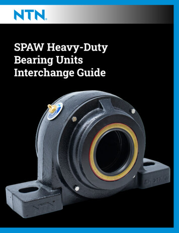
Chapter1Getting StartedThe DeviceNet adapter is a communication option intended for installation intoa PowerFlex 525 drive. The Multi-Drive feature (Chapter 7) also provides ameans for other supported PowerFlex drives and DSI Hosts to connect to aDeviceNet network.TopicComponentsFeaturesUnderstanding Parameter TypesCompatible ProductsRequired EquipmentSafety PrecautionsQuick StartComponentsPage9101011111213Components of the DeviceNet Adapter25-COMM-DItem Part➊Node onSwitches for setting the node address andnetwork data rate. Chapter 2, Installing theAdapter.Communication card- A 40-pin, double-row shrouded femaleDrive headerheader. An interface connector is used toconnect this header to a header on the drive.Status indicatorsThree LEDs that indicate the status of theconnected drive, adapter and network. SeeChapter 8, TroubleshootingCS1/CS2 terminals Provides a clean ground for thecommunication bus cable shields.CS1 or CS2 should be connected to a cleanground or PE ground on the drive.DeviceNet connector A 5-pin connector to which a 5-pin linearplug can be connected.➌➎Rockwell Automation Publication 520COM-UM002A-EN-E - April 20139
Chapter 1Getting StartedFeaturesThe features of the DeviceNet adapter include: Mounting onto a PowerFlex 525 Control Module back cover forinstallation into the drive. It receives the required power from the driveand from the DeviceNet network. Switches to set a node address and network data rate before applyingpower to the PowerFlex drive. Alternatively, you can disable the switchesand use parameters to configure these functions. Compatibility with various configuration tools to configure theDeviceNet adapter and host drive. The tools include network softwaresuch as RSNetWorx for DeviceNet, and drive-configuration software suchas RSLogix 5000 (version 17 or greater), Logix Designer (version 21 orgreater), and Connected Components Workbench (version 3 or greater). Status indicators that report the status of the DeviceNet adapter andnetwork communications. Parameter-configured 16-bit Datalinks in the I/O to meet applicationrequirements (four Datalinks to write data from the network to the drive,and four Datalinks to read data to the network from the drive). Explicit Messaging and UCMM (Unconnected Message Manager)support. Master-Slave hierarchy that can be configured to transmit data to and froma controller on the network. Multi-drive mode which allows up to five drives to share a singleDeviceNet address node. User-defined fault actions to determine how the DeviceNet adapter and itshost PowerFlex 525 drive respond to:– I/O messaging communication disruptions (Comm Flt Action)– Controllers in idle mode (Idle Flt Action) Multiple data exchange methods, including Polled, Cyclic, and Change ofState (COS), can be used to transmit data between the network andadapter. Faulted node recovery is supported. You can configure a device even whenit is faulted on the network if you have a configuration tool that usesfaulted node recovery and have properly set the adapter node addressswitches and data rate switches.Understanding ParameterTypesThis manual references two types of parameters: Device parameters are used to configure the adapter to operate on thenetwork. These parameters reside on the adapter. Host parameters are used to configure the drive, including the datalinkconfiguration for the datalinks used by the adapter. These parametersreside on the drive.10Rockwell Automation Publication 520COM-UM002A-EN-E - April 2013
Getting StartedChapter 1You can view adapter Device parameters and Host parameters with any of thefollowing drive configuration tools: PowerFlex 4-class HIM (22-HIM-A3 or 22-HIM-C2S) Connected Components Workbench software – click the tab for theadapter at the bottom of the window, and click the Parameters icon in thetool bar.Compatible ProductsAt the time of publication, the DeviceNet adapter is compatible with AllenBradley PowerFlex 525 drives.Required EquipmentEquipment Shipped with the DriveWhen you unpack the adapter, verify that the package includes: One PowerFlex 520-series DeviceNet communications adapter (25-COMM-D)(installed in a PowerFlex 520-series drive control module back cover) One 5-pin inline DeviceNet plug (connected to the DeviceNet connector on the adapter) Two interface connectors (for connecting the Communication card-Drive header to the header on the drive) Installation leaflet (publication 520COM-IN001)User-Supplied EquipmentThe adapter parameters can be configured using the drive keypad interface (seeUsing the Drive Keypad Interface to Access Parameters on page 23). In addition,you must supply: DeviceNet cable (thin cable with an outside diameter of 6.9 mm (0.27 in.) is recommended) Controller configuration software, such as:– RSNetWorx for DeviceNet– RSLogix 5000 or Logix Designer– Connected Components Workbench (version 3 or greater)Rockwell Automation Publication 520COM-UM002A-EN-E - April 201311
Chapter 1Getting StartedSafety PrecautionsPlease read the following safety precautions carefully.ATTENTION: Risk of injury or death exists. The PowerFlex drive may containhigh voltages that can cause injury or death. Remove all power from thePowerFlex drive, and then verify power has been removed before installing orremoving an adapter.ATTENTION: Risk of injury or equipment damage exists. Only personnelfamiliar with drive and power products and the associated machinery shouldplan or implement the installation, start up, configuration, and subsequentmaintenance of the drive using this DeviceNet adapter. Failure to comply mayresult in injury and/or equipment damage.ATTENTION: Risk of equipment damage exists. The adapter contains ESD(Electrostatic Discharge) sensitive parts that can be damaged if you do notfollow ESD control procedures. Static control precautions are required whenhandling the adapter. If you are unfamiliar with static control procedures, seeGuarding Against Electrostatic Damage (publication 8000-4.5.2)ATTENTION: Risk of injury or equipment damage exists. If the adapter istransmitting control I/O to the drive, the drive may fault when you reset theadapter. Determine how your drive will respond before resetting the adapter.ATTENTION: Risk of injury or equipment damage exists. Device parameters 15[Comm Flt Actn] and 16 [Idle Flt Actn] let you determine the action of theadapter and drive if I/O communication is disrupted, the controller is idle, orexplicit messaging for drive control is disrupted. By default, these parametersfault the drive. You may configure these parameters so that the drive continuesto run, however, precautions should be taken to ensure that the settings ofthese parameters do not create a risk of injury or equipment damage. Whencommissioning the drive, verify that your system responds correctly to varioussituations (for example, a disconnected cable or a controller in idle state).ATTENTION: Risk of injury or equipment damage exists. When a system isconfigured for the first time, there may be unintended or incorrect machinemotion. Disconnect the motor from the machine or process during initial systemtesting.ATTENTION: Risk of injury or equipment damage exists. The examples in thispublication are intended solely for purposes of example. There are manyvariables and requirements with any application. Rockwell Automation, Inc.does not assume responsibility or liability (to include intellectual propertyliability) for actual use of the examples shown in this publication.12Rockwell Automation Publication 520COM-UM002A-EN-E - April 2013
Getting StartedQuick StartChapter 1This section is provided to help experienced users quickly start using theDeviceNet adapter. If you are unsure how to complete a step, refer to thereferenced chapter.Step Action1Review the safety precautions for the adapter.2Verify that the PowerFlex drive is properly installed.345678910Commission the adapter.Set a unique node address and the appropriate data rate using the switches on theadapter. If desired, you can disable the switches and use parameter settings instead.Install the adapter.Verify that the PowerFlex drive is not powered. Then, connect the adapter to the driveusing the interface connector (included with adapter).Connect the drive to the DeviceNet network.Verify that the DeviceNet network is not powered. Then, connect the DeviceNetadapter to the network using a DeviceNet cable.Apply power to the drive and to the network.The adapter receives power from the drive and network.a. The status indicators should be green. If they flash red, there is a problem. SeeChapter 8, Troubleshooting.b. Configure/verify key drive parameters.Configure the adapter for your application.Set DeviceNet adapter parameters for the following functions as required by yourapplication:– Node address– Data rate– I/O configuration– Change of State, Cyclic, or polled I/O data exchange– Fault actionsApply power to the DeviceNet master and other devices on the network.Verify that the master and network are installed and functioning in accordance withDeviceNet standards, and then apply power to them.Configure the scanner to communicate with the adapter.Use a network tool such as RSNetWorx for DeviceNet to configure the scanner on thenetwork. Make sure to:– Set up the scan list.– Map the adapter data to the scan list.– Save your DeviceNet configuration to the scanner and a file.Create a ladder logic program.Use a controller configuration tool such as RSLogix 5000/Logix Designer to create aladder logic program that enables you to:– Control the adapter and drive using I/O.– Monitor or configure the drive using Explicit messages.Rockwell Automation Publication 520COM-UM002A-EN-E - April 2013See.Throughout this manualPowerFlex 525Adjustable Frequency ACDrive User Manual(publication 520-UM001)Chapter 2,Installing the AdapterChapter 3,Configuring the AdapterDeviceNet Planning andInstallation Manual(ODVA pub 27)Chapter 4,Configuring the I/OChapter 5,Using the I/OChapter 6,Using Explicit Messaging13
Chapter 1Getting StartedNotes:14Rockwell Automation Publication 520COM-UM002A-EN-E - April 2013
Chapter2Installing the AdapterChapter 2 provides instructions for installing the DeviceNet adapter in aPowerFlex 525 drive.TopicPreparing for an InstallationCommissioning the AdapterConnecting the Adapter to the DriveConnecting the Adapter to the NetworkApplying PowerPage1515171920Preparing for an InstallationBefore installing the adapter, do the following: Read the DeviceNet Media Design and Installation Guide, publicationDNET-UM072. Read the DeviceNet Starter Kit User Manual, publication DNETUM003. Verify that you have all required equipment. See Chapter 1, GettingStarted.Commissioning the AdapterTo commission the adapter, you must set a unique node address and the data ratethat is used by the network. (See the Glossary for details about data rates andnode addresses.).There are two methods for configuring the adapter’s Node address and data rate: Using the onboard DIP Switches; Using adapter parameters – Use adapter parameters when you want moreflexibility in setting up the node address. To set the Node address usingadapter parameters, see Setting the Node Address on page 25.IMPORTANTRegardless of the method used to set the adapter’s node address, each node onthe network must have a unique node address. To change a node address, youmust set the new value and then cycle drive power.ATTENTION: Risk of equipment damage exists. The adapter contains ESD(Electrostatic Discharge) sensitive parts that can be damaged if you do notfollow ESD control procedures. Static control precautions are required whenhandling the adapter. If you are unfamiliar with static control procedures, seeGuarding Against Electrostatic Damage (publication 8000-4.5.2)Rockwell Automation Publication 520COM-UM002A-EN-E - April 201315
Chapter 2Installing the AdapterSetting the Node Address and Data Rate Using the DIP east Significant Bit (LSB) of Node AddressBit 1 of Node AddressBit 2 of Node AddressBit 3 of Node AddressBit 4 of Node AddressMost Significant Bit (MSB) of Node AddressLeast Significant Bit (LSB) of Data RateMost Significant Bit (MSB) of Data RateDefault1 Node 63111111 Autobaud1Node Address Switch Settings (UP ON 1)Switch SettingSW 1 SW 2 SW W 400000000111111110000000011111111SW 500000000000000001111111111111111SW itch SettingSW 1 SW 2 SW kwell Automation Publication 520COM-UM002A-EN-E - April 2013SW 400000000111111110000000011111111SW 500000000000000001111111111111111SW 60616263
Installing the AdapterChapter 2Data Rate Switch Settings (UP ON 1)Switch SettingSW 7 SW 800100111Data Rate125 kbps250 kbps500 kbpsAutobaudIMPORTANTIf all switches are in the OFF position (all 0’s), then the Node Address and DataRate are determined by parameter settings (Device parameters 07 [Net AddrCfg] and 09 [Net Rate Cfg]).Setting Single-Drive or Multi-Drive ModeTo select between Single-Drive or Multi-Drive mode, see ParameterConfiguration for Multi-Drive Mode on page 73.Connecting the Adapter tothe DriveATTENTION: Risk of injury or death exists. The PowerFlex drive may containhigh voltages that can cause injury or death. Remove power from the drive, andthen verify power has been discharged before connecting the DeviceNetadapter to the network.1. Remove power from the drive.2. Use static control precautions.3. Separate the drive’s control module from the power module.a. Press and hold down the catch on both sides of the frame cover, thenpullout and swing upwards to remove (Frames B.E only).Rockwell Automation Publication 520COM-UM002A-EN-E - April 201317
Chapter 2Installing the Adapterb. Press down and slide out the top cover of the control module to unlockit from the power module.c. Hold the sides and top of the control module firmly, then pull out toseparate it from the power module.4. Insert the interface connector for the adapter into the header located at theback of the control module.18Rockwell Automation Publication 520COM-UM002A-EN-E - April 2013
Installing the AdapterChapter 25. Align the Communication card-Drive header on the adapter with theinterface connector. Then, press down firmly around the adapter.The adapter snaps into the back of the control module.IMPORTANTThe CS1/CS2 terminals on the adapter provide a clean ground for thecommunication bus cable shields. You should connect the CS1 or CS2terminal to a clean ground or PE ground on the drive.6. Attach the control module to the power module.Connecting the Adapter tothe NetworkATTENTION: Risk of injury or death exists. The PowerFlex drive may containhigh voltages that can cause injury or death. Remove power from the drive, andthen verify power has been discharged before connecting the embeddedEtherNet/IP adapter to the network.1. Remove power from the network.2. Use static control precautions.3. Connect a DeviceNet cable to the network. A DeviceNet thin cable withan outside diameter of 6.9 mm (0.29 in.) is recommended.IMPORTANTMaximum cable length depends on data rate. See the Glossary for DataRate.Rockwell Automation Publication 520COM-UM002A-EN-E - April 201319
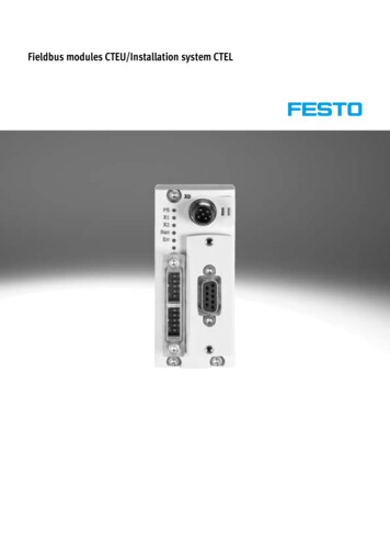
Chapter 2Installing the Adapter4. Connect the 5-pin linear plug to the DeviceNet cable.RedWhiteBareBlueBlack54321Te
The adapter parameters can be configured using the drive keypad interface (see Using the Drive Keypad Interface to Access Parameters on page 23). In addition, you must supply: One PowerFlex 520-series DeviceNet communications adapter (25-COMM-D) (installed in a PowerFlex 520-series drive control module back cover)