Transcription
20B-UM001.book Page 1 Thursday, June 20, 2013 1:55 PMUser ManualPowerFlex 700 AC Drives – Series A, Frames 0 6Standard Control Firmware 3.001 and BelowVector Control Firmware 3.002 and Below
20B-UM001.book Page 2 Thursday, June 20, 2013 1:55 PMImportant User InformationRead this document and the documents listed in the additional resources section about installation,configuration, and operation of this equipment before you install, configure, operate, or maintainthis product. Users are required to familiarize themselves with installation and wiring instructionsin addition to requirements of all applicable codes, laws, and standards.Activities including installation, adjustments, putting into service, use, assembly, disassembly, andmaintenance are required to be carried out by suitably trained personnel in accordance withapplicable code of practice.If this equipment is used in a manner not specified by the manufacturer, the protection provided bythe equipment may be impaired.In no event will Rockwell Automation, Inc. be responsible or liable for indirect or consequentialdamages resulting from the use or application of this equipment.The examples and diagrams in this manual are included solely for illustrative purposes. Because ofthe many variables and requirements associated with any particular installation, RockwellAutomation, Inc. cannot assume responsibility or liability for actual use based on the examples anddiagrams.No patent liability is assumed by Rockwell Automation, Inc. with respect to use of information,circuits, equipment, or software described in this manual.Reproduction of the contents of this manual, in whole or in part, without written permission ofRockwell Automation, Inc., is prohibited.Throughout this manual, when necessary, we use notes to make you aware of safety considerations.WARNING: Identifies information about practices or circumstances that can cause anexplosion in a hazardous environment, which may lead to personal injury or death,property damage, or economic loss.ATTENTION: Identifies information about practices or circumstances that can lead topersonal injury or death, property damage, or economic loss. Attentions help youidentify a hazard, avoid a hazard, and recognize the consequence.IMPORTANTIdentifies information that is critical for successful application and understanding of theproduct.Labels may also be on or inside the equipment to provide specific precautions.SHOCK HAZARD: Labels may be on or inside the equipment, for example, a drive ormotor, to alert people that dangerous voltage may be present.BURN HAZARD: Labels may be on or inside the equipment, for example, a drive ormotor, to alert people that surfaces may reach dangerous temperatures.ARC FLASH HAZARD: Labels may be on or inside the equipment, for example, a motorcontrol center, to alert people to potential Arc Flash. Arc Flash will cause severe injury ordeath. Wear proper Personal Protective Equipment (PPE). Follow ALL Regulatoryrequirements for safe work practices and for Personal Protective Equipment (PPE).PowerFlex, DriveExplorer, DriveExecutive, PLC, Force Technology, DPI, and SCANport are either trademarks or registeredtrademarks of Rockwell Automation, Inc.ControlNet is a trademark of ControlNet International, Ltd.DeviceNet is a trademark of the Open DeviceNet Vendor Association.
20B-UM001.book Page i Thursday, June 20, 2013 1:55 PMSummary of ChangesThe information below summarizes the changes to the PowerFlex 700User Manual, publication 20B-UM001 since the last release.Manual UpdatesDescription of New or Updated InformationPageRemoved the Installation/Wiring information (Chapter 1), Start Up information(Chapter 2), dimension, specification and fuse/breaker information (AppendixA). This information can now be found in the Installation Instructions:PowerFlex 700 Adjustable Frequency AC Drive – Frames 0 6,publication 20B-IN0019–
20B-UM001.book Page ii Thursday, June 20, 2013 1:55 PMsoc-iiNotes:Summary of Changes
20B-UM001.book Page i Thursday, June 20, 2013 1:55 PMTable of ContentsImportant User Information . . . . . . . . . . . 1-2PrefaceOverviewWho Should Use this Manual? . . . . . . . . .What Is Not in this Manual . . . . . . . . . . . .Additional Resources . . . . . . . . . . . . . . . .Manual Conventions . . . . . . . . . . . . . . . . .General Precautions . . . . . . . . . . . . . . . . .Catalog Number Explanation . . . . . . . . . .Chapter 1Programmingand ParametersAbout Parameters . . . . . . . . . . . . . . . . . . . 1-1How Parameters are Organized. . . . . . . . . 1-3Monitor File . . . . . . . . . . . . . . . . . . . . . . 1-12Motor Control File . . . . . . . . . . . . . . . . . 1-14Speed Command File . . . . . . . . . . . . . . . 1-21Dynamic Control File . . . . . . . . . . . . . . . 1-31Utility File . . . . . . . . . . . . . . . . . . . . . . . . 1-38Communication File . . . . . . . . . . . . . . . . 1-50Inputs & Outputs File . . . . . . . . . . . . . . . 1-54Applications File . . . . . . . . . . . . . . . . . . . 1-60Parameter Cross Reference – by Name. . 1-61Parameter Cross Reference – by Number 1-64Chapter 2TroubleshootingFaults and Alarms . . . . . . . . . . . . . . . . . . . 2-1Drive Status . . . . . . . . . . . . . . . . . . . . . . . . 2-2Manually Clearing Faults . . . . . . . . . . . . . 2-3Fault Descriptions . . . . . . . . . . . . . . . . . . . 2-4Clearing Alarms . . . . . . . . . . . . . . . . . . . . 2-9Alarm Descriptions . . . . . . . . . . . . . . . . . 2-10Common Symptoms/Corrective Actions 2-13Testpoint Codes and Functions . . . . . . . . 2-16Appendix ASupplementalDrive InformationDrive Frame Sizes . . . . . . . . . . . . . . . . . . . A-1Communication Configurations . . . . . . . . A-1Appendix BHIM OverviewExternal and Internal Connections . . . . . .LCD Display Elements . . . . . . . . . . . . . . .ALT Functions. . . . . . . . . . . . . . . . . . . . . .Menu Structure . . . . . . . . . . . . . . . . . . . . .Viewing and Editing Parameters . . . . . . . .Linking Parameters (Vector Control Only)Removing/Installing the HIM . . . . . . . . . .P-1P-1P-2P-2P-3P-5B-1B-2B-2B-3B-5B-6B-8
20B-UM001.book Page ii Thursday, June 20, 2013 1:55 PMiiTable of ContentsAppendix CIndexApplication NotesExternal Brake Resistor . . . . . . . . . . . . . . . C-1Lifting/Torque Proving . . . . . . . . . . . . . . . C-2Minimum Speed . . . . . . . . . . . . . . . . . . . . C-7Motor Control Technology . . . . . . . . . . . . C-8Motor Overload . . . . . . . . . . . . . . . . . . . . C-10Overspeed . . . . . . . . . . . . . . . . . . . . . . . . C-11Power Loss Ride Through . . . . . . . . . . . . C-12Process PI for Standard Control . . . . . . . C-13Reverse Speed Limit . . . . . . . . . . . . . . . . C-16Skip Frequency . . . . . . . . . . . . . . . . . . . . C-17Sleep Wake Mode . . . . . . . . . . . . . . . . . . C-19Start At PowerUp. . . . . . . . . . . . . . . . . . . C-21Stop Mode . . . . . . . . . . . . . . . . . . . . . . . . C-22Voltage Tolerance . . . . . . . . . . . . . . . . . . C-24
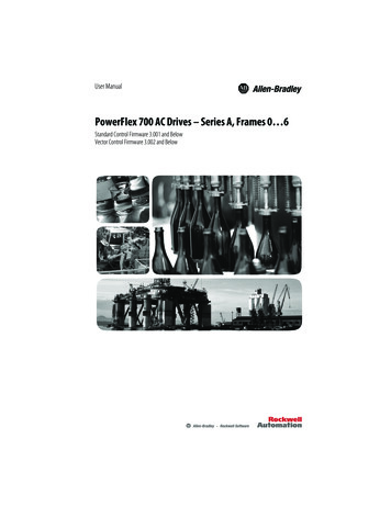
20B-UM001.book Page 1 Thursday, June 20, 2013 1:55 PMPrefaceOverviewThe purpose of this manual is to provide you with the basic informationneeded to install, start-up and troubleshoot the PowerFlex 700Adjustable Frequency AC Drive.For information on . . .Who Should Use this Manual?What Is Not in this ManualAdditional ResourcesManual ConventionsGeneral PrecautionsCatalog Number ExplanationSee page . . .P-1P-1P-2P-2P-3P-5Who Should Use this Manual?This manual is intended for qualified personnel. You must be able toprogram and operate Adjustable Frequency AC Drive devices. Inaddition, you must have an understanding of the parameter settings andfunctions.What Is Not in this ManualThe PowerFlex 700 Series A User Manual provides programming andtroubleshooting information for Standard Control and Vector Controldrives, Frames 0 6.Drive installation and wiring information is not in this manual, but canbe found in the Installation Instructions for your drive:Frames 0 6 – publication 20B-IN019Literature is available online at http://www.rockwellautomation.com/literature.
20B-UM001.book Page 2 Thursday, June 20, 2013 1:55 PMP-2OverviewAdditional ResourcesThese documents contain additional information concerning relatedproducts from Rockwell Automation.ResourceDescriptionPowerFlex 700 AC Drive Technical Data,publication 20B-TD001This publication provides detailed drivespecifications, option specifications and inputprotection device ratings.PowerFlex Comm Adapter Manuals, publication20COMM-UM These publications provide information onconfiguring, using, and troubleshootingPowerFlex communication adapters.PowerFlex 70 and PowerFlex 700 ReferenceManual, publication PFLEX-RM001These publications provide detailed applicationspecific information for programming andconfiguring the PowerFlex 700 drive.PowerFlex 70 Enhanced Control and PowerFlex700 Vector Control Reference Manual,publication PFLEX-RM004Wiring and Grounding Guidelines for PulseWidth Modulated (PWM) AC Drives, publicationDRIVES-IN001Provides basic information needed to properlywire and ground PWM AC drives.Safety Guidelines for the Application, Installationand Maintenance of Solid State Control,publication SGI-1.1Provides general guidelines for the application,installation, and maintenance of solid-statecontrol.Guarding Against Electrostatic Damage,publication 8000-4.5.2Provides practices for guarding againstElectrostatic damage (ESD)Product Certifications website, http://ab.comProvides declarations of conformity, certificates,and other certification details.You can view or download publications athttp:/www.rockwellautomation.com/literature/. To order paper copies oftechnical documentation, contact your local Allen-Bradley distributor orRockwell Automation sales representative.Manual Conventions In this manual we refer to the PowerFlex 700 Adjustable FrequencyAC Drive as; drive, PowerFlex 700 or PowerFlex 700 Drive. To help differentiate parameter names and LCD display text fromother text, the following conventions will be used:–Parameter Names will appear in [brackets].For example: [DC Bus Voltage].–Display Text will appear in “quotes.” For example: “Enabled.”
20B-UM001.book Page 3 Thursday, June 20, 2013 1:55 PMOverview P-3The following words are used throughout the manual to describe anaction:WordCanCannotMayMustShallShouldShould NotMeaningPossible, able to do somethingNot possible, not able to do somethingPermitted, allowedUnavoidable, you must do thisRequired and necessaryRecommendedNot recommendedGeneral Precautions!!!!!ATTENTION: This drive contains ESD (Electrostatic Discharge)sensitive parts and assemblies. Static control precautions are requiredwhen installing, testing, servicing or repairing this assembly.Component damage may result if ESD control procedures are notfollowed. If you are not familiar with static control procedures,reference A-B publication 8000-4.5.2, “Guarding Against ElectrostaticDamage” or any other applicable ESD protection handbook.ATTENTION: An incorrectly applied or installed drive can result incomponent damage or a reduction in product life. Wiring or applicationerrors, such as, undersizing the motor, incorrect or inadequate ACsupply, or excessive ambient temperatures may result in malfunction ofthe system.ATTENTION: Only qualified personnel familiar with adjustablefrequency AC drives and associated machinery should plan orimplement the installation, start-up and subsequent maintenance of thesystem. Failure to comply may result in personal injury and/orequipment damage.ATTENTION: To avoid an electric shock hazard, verify that thevoltage on the bus capacitors has discharged before performing anywork on the drive. Measure the DC bus voltage at the DC & –DCterminals of the Power Terminal Block (refer to Installation Instructionsfor location). The voltage must be zero.ATTENTION: Risk of injury or equipment damage exists. DPI orSCANport host products must not be directly connected together via1202 cables. Unpredictable behavior can result if two or more devicesare connected in this manner.
20B-UM001.book Page 4 Thursday, June 20, 2013 1:55 PMP-4Overview!!!ATTENTION: An incorrectly applied or installed bypass system canresult in component damage or reduction in product life. The mostcommon causes are: Wiring AC line to drive output or control terminals. Improper bypass or output circuits not approved by Allen-Bradley. Output circuits which do not connect directly to the motor.Contact Allen-Bradley for assistance with application or wiring.ATTENTION: The “adjust freq” portion of the bus regulator functionis extremely useful for preventing nuisance overvoltage faults resultingfrom aggressive decelerations, overhauling loads, and eccentric loads. Itforces the output frequency to be greater than commanded frequencywhile the drive's bus voltage is increasing towards levels that wouldotherwise cause a fault. However, it can also cause either of thefollowing two conditions to occur.1. Fast positive changes in input voltage (more than a 10% increasewithin 6 minutes) can cause uncommanded positive speed changes.However an “OverSpeed Limit” fault will occur if the speed reaches[Max Speed] [Overspeed Limit]. If this condition is unacceptable,action should be taken to 1) limit supply voltages within thespecification of the drive and, 2) limit fast positive input voltagechanges to less than 10%. Without taking such actions, if thisoperation is unacceptable, the “adjust freq” portion of the busregulator function must be disabled (see parameters 161 and 162).2. Actual deceleration times can be longer than commandeddeceleration times. However, a “Decel Inhibit” fault is generated ifthe drive stops decelerating altogether. If this condition isunacceptable, the “adjust freq” portion of the bus regulator must bedisabled (see parameters 161 and 162). In addition, installing aproperly sized dynamic brake resistor will provide equal or betterperformance in most cases.Important: These faults are not instantaneous. Test results haveshown that they can take between 2-12 seconds tooccur.ATTENTION: Loss of control in suspended load applications cancause personal injury and/or equipment damage. Loads must always becontrolled by the drive or a mechanical brake. Parameters 600-611 aredesigned for lifting/torque proving applications. It is the responsibilityof the engineer and/or end user to configure drive parameters, test anylifting functionality and meet safety requirements in accordance with allapplicable codes and standards.
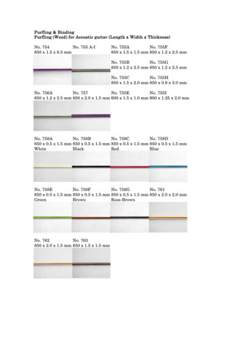
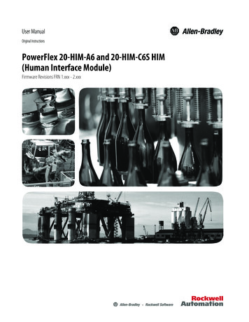
20B-UM001.book Page 5 Thursday, June 20, 2013 1:55 PMOverviewP-5Catalog Number vejHIMCodeTypeCode20BPowerFlex 700bVoltage RatingCodeVoltagePh.Prechg.FramesB240V AC3-0 6C400V AC3-0 6D480V AC3-0 6E600V AC3-0 6F690V AC3-5 6H540V DCComm SlotOperator InterfaceCodeNetwork Type0Blank CoverCControlNet (Coax)3LCD Display, Full Numeric KeypadDDeviceNetJ Remote (Panel Mount), IP66, NEMA/ULType 12 Full Numeric LCD HIMEEtherNet/IPNNoneK Remote (Panel Mount), IP66, NEMA/ULType 12 Prog. Only LCD HIM Available with Frames 5 6 Stand-Alone IP54drives (Enclosure Code "G").kControl & I/OCodefDocumentation-NJ650V DC-N5 6CodeTypeN325V DC-Y5 65 6AManualControlI/O VoltsAStandard24V DC/ACBStandard115V ACVector Δ24V DCDVector Δ115V ACNStandardNoneCP540V DC-Y5 6NNo ManualR650V DC-Y5 6QT810V DC-Y5 6No Shipping Package(Internal Use Only)W932V DC-Y5 6Δ Vector Control Option utilizes DPI Only.lgcFeedbackCodeBrakeTypeND Output RatingCodew/Brake IGBT ‡0NoneExampleYYes1Encoder, 12V/5VNNoCodeAmpskW (Hp)2P22.20.37 (0.5)022225.5 (7.5)‡ Brake IGBT is standard on Frames 0-3,optional on Frames 4-6.mFuture UsedhEnclosurenInternal Braking ResistorCodeEnclosureCodeAIP20, NEMA/UL Type 1YF Open/Flange MountFront: IP00, NEMA/UL Type OpenBack/Heatsink: IP54, NEMA Type 12NG Stand-Alone/Wall MountIP54, NEMA/UL Type 12w/ResistorYesNoNot available for Frame 3 drives or larger. Only available for Frame 5 & Frame 6 drives,400 690V.Special Firmware (Frames 0 6 Only)CodeTypeAD 60 Hz MaximumAE Cascading Fan/Pump ControlAX 82 Hz MaximumBA Pump Off (for pump jack) Must be used with Vector Control option C orD (Position k). Positions m-n are only requiredwhen custom firmware is supplied.iEmissionCodeCE Filter §CM ChokeYesAYesB#YesNoNNoNo§ Note: 600V class drives below 77 Amps(Frames 0-4) are declared to meet the LowVoltage Directive. It is the responsibility of theuser to determine compliance to the EMCdirective.# Only available for 208 240V Frame 0-3 drives.
20B-UM001.book Page 6 Thursday, June 20, 2013 1:55 PMP-6Notes:Overview
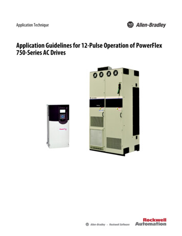
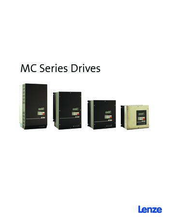
20B-UM001.book Page 1 Thursday, June 20, 2013 1:55 PMChapter 1Programming and ParametersChapter 3 provides a complete listing and description of the PowerFlex700 parameters. The parameters can be programmed (viewed/edited)using an LCD HIM (Human Interface Module). As an alternative,programming can also be performed using DriveExplorer orDriveExecutive software and a personal computer. Refer to AppendixB for a brief description of the LCD HIM.For information on . . .About ParametersHow Parameters are OrganizedMonitor FileMotor Control FileSpeed Command FileDynamic Control FileUtility FileCommunication FileInputs & Outputs FileApplications FileParameter Cross Reference – by NameParameter Cross Reference – by NumberSee page . . ut ParametersTo configure a drive to operate in a specific way, drive parameters mayhave to be set. Three types of parameters exist: ENUM ParametersENUM parameters allow a selection from 2 or more items. The LCDHIM will display a text message for each item. Bit ParametersBit parameters have individual bits associated with features orconditions. If the bit is 0, the feature is off or the condition is false. Ifthe bit is 1, the feature is on or the condition is true. Numeric ParametersThese parameters have a single numerical value (i.e. 0.1 Volts).The example on the following page shows how each parameter type ispresented in this manual.
20B-UM001.book Page 2 Thursday, June 20, 2013 1:55 PMProgramming and ParametersNo.GroupFile➊➋➌➍➎Parameter Name & DescriptionLoads a previously saved set ofparameter values from a selected userset location in drive nonvolatile memoryto active drive ady”“User Set 1”“User Set 2”“User Set 3”199216 [Dig In Status]DiagnosticsStatus of the digitalinputs.DigiDig tal In6iDig tal In5iDig tal Init 4Dig al In3iDig tal Inita 2l In1UTILITYDrive . . .198 [Load Frm Usr Set]➏Related1-2x x x x x x x x x x 0 0 0 0 0 015 14 13 12 11 10 9 8 7 6 5 4 3 2 1 01 Input Present0 Input Not Presentx ReservedNo.➊➋➌Torq . . .MOTOR . . .Bit #434Vector[Torque Ref B Mult]➎➏1.0DescriptionFile – Lists the major parameter file category.Group – Lists the parameter group within a file.No. – Parameter number.32➍Default:FV Defines the value of the multiplier for the Min/Max: –/ 32767.0[Torque Ref B Sel] selection.Units:0.1 Parameter value can not be changed until drive is stopped. 32 bit parameter in the Standard Control option. Allparameters in the Vector Control option are 32 bit.FV Parameter only displayed when [Motor Cntl Sel] is set to “4.”Parameter Name & Description – Parameter name as it appears on an LCD HIM, with a briefdescription of the parameters function.Standard This parameter is specific to the Standard Control Option. This parameter will only be available with the Vector Control option.VectorVector v3 Only available with Vector Control option firmware version 3.xxx & later.Values – Defines the various operating characteristics of the parameter. Three types exist.ENUM Default:Lists the value assigned at the factory. “Read Only” no default.Options:Displays the programming selections available.BitBit:Lists the bit place holder and definition for each bit.Numeric Default:Lists the value assigned at the factory. “Read Only” no default.Min/Max:The range (lowest and highest setting) possible for the parameter.Units:Unit of measure and resolution as shown on the LCD HIM.Important: Some parameters will have two unit values: Analog inputs can be set for current or voltage with [Anlg In Config], param. 320. Setting [Speed Units], parameter 79 on Vector Control drives selects Hz or RPM. Values that pertain to Vector Control drives only will be indicated by “ Vector ” or“ v3 ” for Vector firmware 3.xxx and later.Important: When sending values through DPI ports, simply remove the decimalpoint to arrive at the correct value (i.e. to send “5.00 Hz,” use “500”).Related – Lists parameters (if any) that interact with the selected parameter. The symbol “ ”indicates that additional parameter information is available in Appendix C.
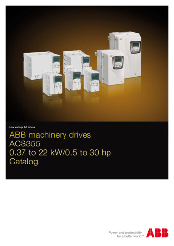
20B-UM001.book Page 3 Thursday, June 20, 2013 1:55 PMProgramming and Parameters1-3How Parameters are OrganizedThe LCD HIM displays parameters in a File-Group-Parameter orNumbered List view order. To switch display mode, access the MainMenu, press ALT, then Sel while cursor is on the parameter selection. Inaddition, using [Param Access Lvl], the user has the option to display allparameters, commonly used parameters or diagnostic parameters.Control OptionsTwo different control options areavailable for the PowerFlex 700;Standard and Vector. The StandardControl option provides typical Voltsper Hertz and Sensorless Vectoroperation. The Vector Control optionprovides the added capability of FVCVector control. The cassettedetermines the type of control youhave available (see diagram).Standard ControlOptionVector ControlOptionTo simplify programming with theVector Control option, the displayedparameters will change according tothe selection made with [Motor CntlSel]. For example, if “FVC Vector” isselected, the parameters associated solely with other operations such asVolts per Hertz or Sensorless Vector will be hidden. Refer to pages 1-4through 1-8.File-Group-Parameter OrderThis simplifies programming by grouping parameters that are used forsimilar functions. The parameters are organized into files. Each file isdivided into groups, and each parameter is an element in a group. Bydefault, the LCD HIM displays parameters by File-Group-Parameterview.Numbered List ViewAll parameters are in numerical order.
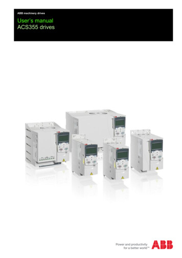
20B-UM001.book Page 4 Thursday, June 20, 2013 1:55 PM1-4Programming and ParametersBasic Parameter View – Standard Control OptionParameter 196 [Param Access Lvl] set to option 0 ut FreqCommanded FreqOutput CurrentDC Bus Voltage001002003012Motor DataMotor NP VoltsMotor NP FLAMotor NP Hertz041042043Torq AttributesTorque Perf Mode 053Maximum Voltage 054Spd Mode &LimitsMinimum Speed 081Maximum Speed 082SpeedReferencesSpeed Ref A Sel 090Speed Ref B Sel 093Speed Ref A Hi 091DiscreteSpeedsJog Speed100Preset Speed 1-7 101-107Ramp RatesAccel Time 1Accel Time 2140141Load LimitsCurrent Lmt SelCurrent Lmt Val147148Stop/BrakeModesStop Mode AStop Mode BMonitorMotor ControlDynamic ContrUtilityInputs &OutputsInputs&OutputsMotor OL Hertz047Maximum FreqAutotune055061Speed Ref B HiSpeed Ref A LoSpeed Ref B Lo094092095TB Man Ref SelTB Man Ref HiTB Man Ref Lo096097098Decel Time 1Decel Time 2142143S-Curve %146155156DC Brk Lvl SelDC Brake LevelDC Brake Time157158159Bus Reg Mode A 161Bus Reg Mode B 162DB Resistor Type 163Restart ModesStart At PowerUp 168Auto Rstrt Tries174Auto Rstrt DelayPower LossPower Loss Mode 184Power Loss Time 185olUtilityMotor NP RPM044Motor NP Power 045Mtr NP Pwr Units 046Direction Config Direction Mode190Drive MemoryParam Access Lvl 196Reset To Defalts 197Load Frm Usr Set 198FaultsFault Config 1238Analog InputsAnlg In ConfigAnalog In1 HiAnalog In2 Hi320322325Analog Outputs Analog Out1 SelAnalog Out1 HiAnalog Out1 LoSave To User Set 199Language201Analog In1 LoAnalog In2 Lo323326Dig Out1 LevelDig Out2 Level381385342343344Digital InputsDigital In1-6 Sel361-366Digital OutputsDigital Out1 SelDigital Out2 Sel380384175
20B-UM001.book Page 5 Thursday, June 20, 2013 1:55 PMProgramming and Parameters1-5Basic Parameter View – Vector Control OptionParameter 196 [Param Access Lvl] set to option 0 ut Freq001Commanded Speed002Commanded Torque**024Output Current003Torque Current004DC Bus Voltage 012Motor DataMotor NP VoltsMotor NP FLAMotor NP Hertz041042043Motor NP RPM044Motor NP Power 045Mtr NP Pwr Units 046Motor OL HertzMotor PolesTorq AttributesMotor Cntl SelMaximum VoltageMaximum FreqAutotune053054055061Autotune Torque** 066Inertia Autotune** 067Torque Ref A Sel** 427Torque Ref A Hi** 428Torque Ref A Lo** 429Pos Torque Limit** 436Neg Torque Limit** 437SpeedFeedbackMotor Fdbk Type 412Encoder PPRSpd Mode &LimitsSpeed Units079Feedback Select 080Minimum Speed 081Maximum Speed 082Rev Speed Limit** 454SpeedReferencesSpeed Ref A SelSpeed Ref A HiSpeed Ref A LoSpeed Ref B SelSpeed Ref B HiSpeed Ref B LoTB Man Ref SelTB Man Ref HiTB Man Ref LoPulse Input Ref098099DiscreteSpeedsJog Speed 1100Jog Speed 2Preset Speed 1-7 101-107108Ramp RatesAccel Time 1Accel Time 2140141Decel Time 1Decel Time 2142143S-Curve %146Load LimitsCurrent Lmt Sel147Current Lmt Val148Stop/BrakeModesStop/Brk Mode A 155Stop/Brk Mode B 156DC Brk Lvl SelDC Brake LevelDC Brake Time157158159Restart ModesStart At PowerUp 168Auto Rstrt Tries174Power LossPower Loss Mode 184Power Loss Time 185Power Loss Level 186MonitorMotor ControlDynamic Contr413094095096097olUtilityUtilityInputs &OutputsInputs&090091092093047049OutputsDirection Config Direction ModeBus Reg Mode A 161Bus Reg Mode B 162DB Resistor Type 163Auto Rstrt Delay175190Drive MemoryParam Access Lvl 196Reset To Defalts 197Load Frm Usr Set 198Save To User Set 199Language201DiagnosticsStart Inhibits214Dig In Status216Dig Out Status217FaultsFault Config 1238AlarmsAlarm Config 1259Analog InputsAnlg In ConfigAnalog In1 HiAnalog In1 Lo320322323Analog In2 HiAnalog In2 Lo325326Analog Outputs Analog Out1, 2 Sel 342Analog Out1 Hi 343Analog Out1, 2 Lo 344Analog Out1, 2 Sel 345Digital InputsDigital In1-6 SelDigital OutputsDigital Out1-3 Sel 380-388 Dig Out1-3 Level 381-389Analog Out2 Hi 346Analog Out1, 2 Lo 347361-366** These parameters will only be displayed when parameter 053 [Motor Cntl Sel] is set to option “4.”
20B-UM001.book Page 6 Thursday, June 20, 2013 1:55 PM1-6Programming and ParametersAdvanced Parameter View – Standard Control OptionParameter 196 [Param Access Lvl] set to option 1 utput FreqCommanded FreqOutput CurrentTorque CurrentFlux Current001002003004005Output Voltage006Output Power007Output Powr Fctr 008Elapsed MWh009Elapsed Run Time 010Drive DataRated kWRated Volts026027Rated AmpsControl SW Ver028029Motor DataMotor TypeMotor NP VoltsMotor NP FLAMotor NP Hertz040041042043Motor NP RPMMotor NP PowerMtr NP Pwr UnitsMotor OL HertzTorq AttributesTorque Perf ModeMaximum VoltageMaximum FreqCompensation053054055056Flux Up ModeFlux Up TimeSV Boost FilterAutotuneVolts per HertzStart/Acc BoostRun Boost069070Break Voltage071Break Frequency 072Spd Mode &LimitsSpeed Mode080Minimum Speed 081Maximum Speed 082Overspeed Limit 083Skip Frequency 1 084Skip Frequency 2 085Skip Frequency 3 086Skip Freq Band 087SpeedReferencesSpeed Ref A Sel 090Speed Ref A Hi 091Speed Ref A Lo 092Speed Ref B Sel 093Speed Ref B Hi 094Speed Ref B Lo 095TB Man Ref SelTB Man Ref HiTB Man Ref Lo096097098DiscreteSpeedsJog Speed100Preset Speed 1-7 101-107Speed TrimTrim In SelectTrim Out SelectSlip CompMonitorMotor ControlMotorControlSpeedCommandSpeedMOP FrequencyDC Bus VoltageDC Bus MemoryAnalog In1 ValueAnalog In2 Value011012013016017044045046047Motor OL Factor048057058059061IR Voltage Drop 062Flux Current Ref 063IXo Voltage Drop 064CommandDynamicControlDynamic ContrTrim HiTrim Lo119120Slip RPM @ FLA 121Slip Comp Gain 122Slip RPM Meter123Process PIPI ConfigurationPI ControlPI Reference SelPI SetpointPI Feedback Sel124125126127128PI Integral TimePI Prop GainPI Lower LimitPI Upper LimitPI Preload129130131132133PI StatusPI Ref MeterPI Fdback MeterPI Error MeterPI Output Meter134135136137138Ramp RatesAccel Time 1Accel Time 2140141Decel Time 1Decel Time 2142143S Curve %146Load LimitsCurrent Lmt Sel 147Current Lmt Val 148Current Lmt Gain 149Drive OL Mode150PWM Frequency 151Stop/BrakeModesStop Mode AStop Mode BDC Brake Lvl SelDC Brake Level155156157158DC Brake TimeBus Reg KiBus Reg Mode ABus Reg Mode B159160161162DB Resistor Type 163Bus Reg Kp164Bus Reg Kd165Restart ModesStart At PowerUpFlying Start EnFlying StartGainAuto Rstrt Tries168169170174Auto Rstrt DelaySleep Wake-ModeSleep-Wake RefWake Level175178179180Wake TimeSleep LevelSleep TimePower LossPower Loss Mode 184Power Loss Time 185Power Loss Level 186ol117118181182183
20B-UM001.book Page 7 Thursday, June 20, 2013 1:55 PMProgramming and ParametersFileGroupUtilityDirection Config Direction ModeParameters190HIM Ref Config Save HIM Ref192Man Ref Preload 193UtilityMOP ConfigSave MOP RefMOP RateDrive MemoryParam Access Lvl 196Reset To Defalts 197Load Frm Usr Set 198Save To User Set 199Reset Meters200Language201Voltage ClassDrive Checksum202203DiagnosticsDrive Status 1Drive Status 2Drive Alarm 1Drive Alarm 2Speed Ref SourceStart InhibitsLast Stop SourceDig In Status209210211212213214215216Dig Out StatusDrive TempDrive OL CountMotor OL CountFault SpeedFault AmpsFault Bus VoltsStatus 1 @ FaultStatus 2 @ FaultAlarm 1 @ FaultAlarm 2 @ FaultTestpoint 1 SelTestpoint 1 DataTestpoint 2 SelTestpoint 2 Data228229230234235236237FaultsFault Config 1Fault Clear238240Fault Clear Mode 241Power Up Marker 242Fault 1-8 CodeFault 1-8 Time243-257244-258AlarmsAlarm Config 1Alarm Clear259261Alarm1-8 Code262-269DPI Baud RateDrive Logic Rslt270271Drive Ref RsltDrive Ramp Rslt272273Masks &OwnersLogic MaskStart MaskJog MaskDirection MaskReference MaskAccel MaskDecel Mask276277278279280281282Fault Clr MaskMOP
AC Drive as; drive, PowerFlex 700 or PowerFlex 700 Drive. To help differentiate parameter names and LCD display text from other text, the following conventions will be used: - Parameter Names will appear in [brackets]. For example: [DC Bus Voltage]. - Display Text will appear in "quotes." For example: "Enabled." Additional Resources