Transcription
Design of a Boost ConverterSubmitted byAbdul Fathah (109EE0612)Department of Electrical EngineeringNational Institute of Technology Rourkela-1-
Design of a Boost ConverterA Thesis submitted in partial accomplishment for the degree ofBachelor of Technology in “Electrical Engineering”ByAbdul Fathah (109EE0612)Under guidance ofProf. B.D. SubudhiDepartment of Electrical EngineeringNational Institute of TechnologyRourkela-769008 (ODISHA)June-2013-2-
DEPARTMENT OF ELECTRICAL ENGINEERINGNATIONAL INSTITUTE OF TECHNOLOGY, ROURKELAODISHA, INDIA-769008CERTIFICATEThis is to certify that the thesis entitled “Design of a Boost Converter”, submitted by AbdulFathah (Roll. No. 109EE0612), in partial fulfillment for the award of Bachelor of Technologyin “Electrical Engineering” during session 2012-2013 at National Institute of Technology,Rourkela. An authentic record of research work carried out by him under my supervision andguidance.The student has fulfilled all the recommended requirements.The Thesis is based on candidate’s own work, has not submitted elsewhere for a degree/diploma.In my opinion, this thesis is of standard required for the award of a bachelor of technologydegree in Electrical Engineering.Place: RourkelaDept. of Electrical EngineeringProf. B.D. SubudhiNational institute of TechnologyProject SupervisorRourkela-769008-3-
ACKNOWLEDGEMENTSOn the submission of my thesis entitled “Design of a Boost Converter”, as a final yearproject, I would like to extend my appreciation & my sincere thanks to my project supervisor, avery generous guide in fact, Prof. B.D. Subudhi, Department of Electrical Engineering for hisceaseless encouragement and support during the course of my work. I verily appreciate and valuehis prestigious guidance and motivation from the beginning to the end of this work. Hisknowledge and support at the time of crisis will be remembered lifelong. He has been greatsource of inspiration to me and I thank him from the bottom of our hearts.I would also like to thank the staff of Electrical engineering department for constantsupport and providing place to work during project period. Last but not the least I would also likethank my friends, specially Soumya Ranjan Panda and Subhransu Satpathy who was withme during thick and thin.Abdul FathahB. Tech (Electrical Engineering)a
Dedicated toMy beloved parentsb
ABSTRACTThe switching mode power supply market is flourishing quickly in today’sworld. Design engineers aren’t always supplied with the desired amount ofvoltage they need in order to make their design function properly. Adding anextra voltage supply to a design is not always cost efficient. This thesis isproposed to provide the designer with a method of boosting DC voltage from5 Volts to 15 Volts, by using a boost converter designed specifically for thistask. All aim, calculations, tests, data and conclusions have been documentedwithin this report. Results of simulation show that the switching converterwill boost voltage from 5 volts to 15 volts with power conversion efficiency of94.16 percent.i
CONTENTSACKNOWLEDGEMENTSaABSTRACTiTABLE OF CONTENTSiiLIST OF FIGURESivCHAPTER 1INTRODUCTION11.1 RATIONALE11.2 PURPOSE OF THE PROJECT1CHAPTER 2BACKGOUND AND LITERATURE REVIEW22.1 OVERVIEW22.2 HISTORY22.3 APPLICATIONS2CHAPTER 3METHODOLOGY43.1 GENERAL BOOST CONVERTER CONFIGURATION43.2 BLOCK DIAGRAM83.3 SPECIFICATIONS93.4 COMPONENT FUNCTIONS93.5 COMPONENT CALCULATIONS93.5.1 LOAD RESISTANCE93.5.2 DUTY CYCLE93.5.3 CAPACITOR103.5.4 INDUCTOR103.5.5 DIODE113.5.6 MOSFET11ii
3.6 LOSS CALCULATION113.6.1 DIODE LOSS113.6.2 SWITCHING LOSS123.6.3 GATE CIRCUIT LOSS123.6.4 CONDUCTION LOSS123.7 EFFICIENCY133.8 TRANSFER FUNCTION13CHAPTER 4RESULTS AND OBSERATIONS184.1 MATLAB SIMULATION RESULTS184.2 PSPICE SIMULATION RESULTS194.3 OBSERVATIONS20CHAPTER 5CONCLUSION21REFERENCES22iii
LIST OF FIGURESFigure 3.1.1 - Circuit Diagram of Boost Converter4Figure 3.1.2 - Circuit operation (a) Mode 1 and (b) Mode 25Figure 3.1.3 – Waveforms6Figure 3.2.1 - Block diagram8Figure 3.8.1 - Switch ON equivalent Circuit13Figure 3.8.2 - Switch OFF equivalent circuit16Figure 4.1.1 - Circuit Diagram of Boost Converter used in MATLAB18Figure 4.1.2 - IO (output current) vs Time in MATLAB18Figure 4.1.3 - VOUT(output voltage) vs Time in MATLAB19Figure 4.2.1 - Circuit Diagram of Boost Converter used in PSPICE19Figure 4.2.2 - VOUT(output voltage) vs Time in PSPICE20iv
Chapter 1INTRODUCTION1.1 RATIONALEIn many technical applications, it is required to convert a set voltage DC source into avariable-voltage DC output. A DC-DC switching converter converts voltage directly from DC toDC and is simply known as a DC Converter. A DC converter is equivalent to an AC transformerwith a continuously variable turns ratio. It can be used to step down or step up a DC voltage source,as a transformer.DC converters are widely used for traction motor control in electric automobiles, trolley cars,marine hoists, forklifts trucks, and mine haulers. They provide high efficiency, good accelerationcontrol and fast dynamic response. They can be used in regenerative braking of DC motors to returnenergy back into the supply. This attribute results in energy savings for transportation systems withfrequent steps. DC converters are used in DC voltage regulators; and also are used, with an inductorin conjunction, to generate a DC current source, specifically for the current source inverter. [1]1.2 PURPOSE OF THE PROJECTEfficiency, size, and cost are the primary advantages of switching power converters whencompared to linear converters. The switching power converter efficiencies can run between 7080%, whereas linear converters are usually 30% efficient. The DC-DC Switching Boost Converteris designed to provide an efficient method of taking a given DC voltage supply and boosting it to adesired value.1
Chapter 2BACKGROUND AND LITERATURE OVERVIEW2.1 OVERVIEWPower for the boost converter can come from any suitable DC sources, such as DCgenerators, batteries, solar panels and rectifiers. The method that changes one DC voltage to adifferent DC voltage is called DC to DC conversion. Generally, a boost converter is a DC to DCconverter with an output voltage greater than the source voltage. It is sometimes called a step-upconverter since it “steps up” the source voltage. [2]2.2 HISTORYFor high efficiency, the SMPS switch must turn on and off quickly and have very lesslosses. The coming of a commercial semiconductor switch such as the boost converter in the 1950srepresented a major milestone that made SMPSs possible. The main DC to DC converters weredeveloped in the early 1960s when semiconductor switches were available.Switched systems such as SMPS are a challenge to design since its model depends on whether aswitch is opened or closed. R. D. Middlebrook from Caltech in 1977 published the models for DCto DC converters in market today. He averaged the circuit configurations for each switch state in atechnique called state-space average modelling. This simplification resulted in reduction of twosystems into one. This model led to insightful design equations which helped SMPS growth. [2]2.3 APPLICATIONSBattery powered systems often stack cells in series to obtain higher voltage. However,sufficient heaping of cells is not possible in many high voltage applications due to insufficientspace. Boost converters can increase the voltage and reduce the cell numbers. Two battery-poweredapplications that use boost converters are hybrid electric vehicles (HEV) and lighting systems.The NHW20 model Toyota Prius HEV utilizes 500 V. If there is no boost converter, the HEVwould need nearly 417 cells to power its motor. In reality, a Prius actually uses only 168 cells andboosts the battery voltage from 202 V to 500 V. On a smaller scale application, boost convertersalso power devices such as portable lighting systems and emergency lights. A white LED typically2
requires 3.3 V to function, and a boost converter can step up the voltage from a single 1.5 Valkaline cell to power the light. It can also produce higher voltages to operate coldcathode fluorescent tubes (CCFL) in devices such as LCD backlights and some flashlights.A boost converter is used as the voltage increase mechanism in the circuit known as the 'Joule thief',which is a circuit topology used with low power battery applications, and is purposed at the abilityof a boost converter to 'steal' the remaining energy in a battery. The energy remaining wouldotherwise be wasted since the low voltage of a nearly depleted battery makes it unusable for a load.The remaining energy would otherwise remain untapped because many applications do not allowenough current to flow through a load when voltage degrades. This occurs as batteries are degraded,and is a characteristic of a normal battery. [2][3]There are a range of uses for a DC-DC boost converter. Travelers need to carry such deviceswhen they want to bring electronics from home and the supply of current in a foreign countrydiffers from that which is present at their home. Sometimes only a plug converter is required, but inother cases, plugging electronics directly into the power supply could damage the devices. A boostconverter provides a bridge to allow travelers to access electricity safely.Such devices are also used with systems that require high voltage, ranging from theatricallighting to scientific apparatus. The boost converter may in some cases be wired directly into theelectrical supply because of a permanent requirement. In other instances, it becomes necessary toplug the device in as required, especially in the case of traveling equipment like that used by bandson the concerts. As with other electrical devices, it is advisable to inspect a boost converter beforeuse to confirm it is in good working condition and to check for any issues that might impairfunctionality or safety. [4]3
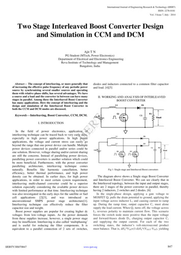
Chapter 3METHODOLOGY3.1 GENERAL BOOST CONVERTER CONFIGURATIONIn a boost converter, the output voltage is greater than the input voltage – hence the name“boost”. A boost converter using a power MOSFET is shown below.Fig. 3.1.1 Circuit diagram of Boost Converter. [1]The function of boost converter can be divided into two modes, Mode 1 and Mode 2. Mode 1begins when transistor M1 is switched on at time t 0. The input current rises and flows throughinductor L and transistor M1.Mode 2 begins when transistor M1 is switched off at time t t1. The input current now flows throughL, C, load, and diode D m. The inductor current falls until the next cycle. The energy stored ininductor L flows through the load.4
The circuits for the two modes of operation are shown below:(a)(b)Fig. 3.1.2 Circuit operation (a) Mode 1 and (b) Mode 2. [1]5
The waveforms for the voltages and currents are shown belowFig. 3.1.3 Waveforms. [1]6
The voltage-current relation for the inductor L is:OrFor a constant rectangular pulse:When the transistor M1 is switched:OrAnd when the transistor is switched off the current is:OrHere VD is the voltage drop across the diode Dm, and VTrans is the voltage drop across the transistorM1.By equating through delta i, we can solve for Vout:7
Neglecting the voltage drops across the diode and the transistor:So it is clear that the output voltage is related directly to the duty cycle. The main challenge whendesigning a converter is the sort of inductor to be used. From above equations, it can be seen thatthe inductance is inversely proportional to the ripple current. So, to reduce the ripple, a largerinductor should be used. [5]3.2 BLOCK DIAGRMFig. 3.2.1 shows the basic blocks of building a boost converter circuit:Magnetic FieldStorage utputRectifier andFig. 3.2.1 Block diagram. [6]FilterThe voltage source provides the input DC voltage to the switch control, and also to the magneticfield storage element. The block which contains switch control directs the action of the switchingelement, whereas the output rectifier and filter deliver an acceptable DC voltage to the output. [6]8
3.3 SPECIFICATIONSEngineers working in today’s high tech environment have to deal with a rapidly changingmarket of electronic products and equipments. As new technologies are invented, integrated circuitsfunction faster and are smaller in size and shape. But, many integrated circuits still require a voltageof 15 volts to function. The DC-DC Switching Boost Converter will take a 5 Volt DC voltagesupply with 10 % tolerance and deliver 15 Volts to the load. The maximum current delivered tothe load will be 0.4 A. The circuit will operate with a minimum efficiency of 94.16%. [7]3.4 COMPONENT FUNCTIONSThe inductor shown in Fig. 3.1.1 acts as the magnetic field storage element shown in Fig.3.2.1. It stores energy in its core material. The ideal PWM functions as the switch control and thetransistor acts as the switch element. The diode and the capacitor are used to perform the function ofthe output rectifier and filter block.3.5 COMPONENT CALCULATIONS3.5.1 LOAD RESISTANCELoad Resistance Assuming Io to be 0.4ALoad Resistance 3.5.2 DUTY CYCLEDuty Cycle 0.679 37.5Ω
3.5.3 CAPACITOR 2.622 10-3V V ESRC C 2.034 10-3FNew Ripple Voltage Capacitor Specifications Low ESR Tantanum CapacitorNo. - TRSE 22006K050R002Capacitance - 2.2mFMaximum O/P Voltage - 50VTolerance - 10%3.5.4 INDUCTORL Ripple current Io 10% of IoL 870µHInductor Specifications –Family – 54zMinimum Quality Factor – 27 at 8MHzTest Frequency – 8MHzTolerance – 10%10 2.424 10-3V
Lead Style – AxialType – Lower ChokeProduct Length – 19mmDiameter – 0.8mmTechnology- Wire WoundInductance – 1mH3.5.5 DIODEDiode Specifications –No. - IN5820Maximum voltage – 30VMaximum Current – 5ASchottky DiodeForward voltage drop at peak current 0.4V3.5.6 MOSFETMOSFET Specifications –Output Voltage – 30VLoad Current – 5ARDS 0.002ΩF 50 KHzN Channel MOSFET. [5]3.6 LOSS CALCULATION3.6.1 DIODE LOSSDiode loss Vd Io(1-D) 0.07 W11
3.6.2 SWITCHING LOSSVGS VThresholdE1 t1E2 t2Psw (t1 t2)fs3.6.3 GATE CIRCUIT LOSSAssumingRdriver pull up 5ΩRdriver pull down 2ΩRgate 1.5ΩVDD 10VWhen gate signal is risingI 0.31A 168.8nst1 t2 22.8nsSo,Psw (t1 t2)fs 0.3 W3.6.4 CONDUCTION LOSSIo2 D R 0.21mW12
3.7 EFFICIENCYEfficiency Efficiency 94.16%3.8 TRANSFER FUNCTIONState Space Average ModelSwitch ON equivalent circuitFig. 3.8.1 Switch ON equivalent Circuit.13
Applying KVL & KCL Vin - RON iL - RL iLVout io R 0AndVout Vc ic RcVout VcFrom above, iin iLState equation matrices are given as: AndVout So, A, B, C, D parameters areAON BON 14Vin
CON DON Now for the circuitAON BON CON L Vin – RON iL – RL iL – Vout RD iLic i L - iRAndVout Vc ic RcVout Vc iL R cOrVout Vc iLFrom above equationL Vin –iL – VcAlso,ic i L - iR15
C iL -Fig. 3.8.2 Switch OFF equivalent circuit.State equation matrices are given as- Vout Parameters areAoff Boff 16Vin
Coff Doff Now adding the weighted average of parametersAavg AON d (1 - d) AoffAavg Bavg Cavg Davg Transfer Function 17
Chapter 4RESULTS AND OBSERVATIONS4.1 MATLAB SIMULATION RESULTS:Given below is a circuit diagram used for MATLAB simulation of boost converter. The purpose ofthis circuit is to measure output voltage and current waveformFig. 4.1.1 Circuit Diagram of Boost Converter used in MATLAB.Given below is the output current waveform obtained from MATLAB simulationFig.4.1.2 (IO(output current) vs Time) in MATLAB.18
Given below is the output voltage waveform obtained from MATLAB simulationFig. 4.1.3 (VOUT(output voltage) vs Time) in MATLAB.The frequency of operation is 50 kHz. Fig. 8 shows the output current obtained from simulation,which is 0.4 A. Fig. 9 shows the output voltage obtained from simulation, which is 15 V. DutyCycle is maintained above 50%.4.2 PSPICE SIMULATION RESULTS:Given below is a circuit diagram used for PSPICE simulation of boost converter. The purpose ofthis circuit is to measure output voltage across the resistor R1Fig. 4.2.1 Circuit Diagram of Boost Converter used in PSPICE.19
Given below is the output voltage waveform obtained from PSPICE simulationFig. 4.2.2 VOUT(output voltage) vs Time in PSPICE.The above figure shows that the output voltage across the resistor R1 (37.5 Ω) becomes stable aftersometime, and remains at 15 V.4.3 OBSERVATIONS:From the results obtained, it is clearly observed that the boost converter steps up the voltage from 5to 15 volt in accordance with the parameters derived earlier, fulfilling the desired conditions ofoutput current being 0.4 A at frequency 50kHz. The efficiency of the boost converter is 94.16%.20
Chapter 5CONCLUSIONAll of the specifications stated previously have been met by this boost converter design.MATLAB and PSPICE simulations using calculated parameters were performed and correspondingwaveforms were obtained. The output voltage across the output capacitor is 15V with a maximumoutput ripple of 1.6%. The power efficiency of the circuit exceeds 94 %. However an additionalconstraint needs to be put on the load. The load must not exceed 0.75kΩ. This will cause theefficiency to fall below the specified value of 94.16%. Hardware design of BOOST outputvoltagealsochanges.
REFERENCES[1]Muhammad H. Rashid, “Power Electronics, Circuits, Devices, and Applications”, ThirdEdition, Pearson Education, Inc., 2004.[2]Carl Nelson & Jim Williams, “Linear Technology, LT1070 Design Manual”, 1986.[3]Marty Brown, “Practical Switching Power Supply Design”, New York: Academic Press,Inc., 1990.[4]Irving M. Gottlieb, “Power Supplies, Switching Regulators, Inverters, & Converters”, NewYork: McGraw-Hill, 1993.[5]D. M. Mitchell, “DC-DC Switching Regulator Analysis”, New York: McGraw-Hill, 1988.[6]Anita Soni, “DC-DC Switching Boost Converter”, ILLINOIS College of Engineering, 1999.[7]G. Seguier, “Power Electronic Converters: DC-DC Conversion”, New York, SpringerVerlag, Inc., 1993.22
3.1 GENERAL BOOST CONVERTER CONFIGURATION In a boost converter, the output voltage is greater than the input voltage - hence the name "boost". A boost converter using a power MOSFET is shown below. Fig. 3.1.1 Circuit diagram of Boost Converter. [1] The function of boost converter can be divided into two modes, Mode 1 and Mode 2. Mode 1