Transcription
Allegro PSpice SimulatorA unified environment for PCB design, simulation, and analysisOn larger designs especially, PCB design teams need fast and reliable simulation to achieveconvergence. The Cadence Allegro PSpice Simulator provides simulation technology for PCBdesign that offers a single, unified design environment for both simulation and PCB design. Withintegrated analog and event-driven digital simulation, teams benefit from improved speed without sacrificing accuracy. Using advanced analysis capabilities, designers can automatically maximizethe performance of circuits.Cadence SimulationTechnology for PCB DesignThe Allegro PSpice Simulator providesa full-featured analog simulator withsupport for digital e lements to helpsolve virtually any design challenge—from high-frequency systems tolow-power IC designs. The powerfulsimulation engine integrates easily withCadence PCB schematic entry solutions,improving time to market andkeeping operating costs in check. Aninteractive, easy-to-use graphical userinterface p rovides complete controlover the design process. Availabilityof resources such as models frommany vendors, built-in mathematicalfunctions, and behavioral modelingtechniques make for an efficient designprocess. Advanced analysis f eatures(Sensitivity, Monte Carlo, Smoke,parametric plotter, and an optimizerwith multiple engines) are built on topof the simulator to improve designperformance, cost-effetiveness, andreliability. The Allegro PSpice Simulatornow offers the new Device ModelInterface feature for automatingthe code generation for multilevelabstraction models written in C/C ,and SystemC , Verilog A-ADMS, anda set of behavioral analog devices andcontrolled sources.The products are tightly integratedwith Cadence Allegro Design EntryHDL and Cadence OrCAD Capture /CIS. The simulation technology canalso interface with MathWorks’MATLAB Simulink package in apowerful co-simulation environment(SLPS). (See Figure 1.)Benefits Improves simulation times, reliability,and convergence on larger designs Improves speed without loss of accuracy via integrated analog andevent-driven digital simulations Explores circuit behavior usingbasic DC, AC, noise, and transientanalyses Allows system-level interfaces to betested with actual electrical designsusing SLPS Offers library selection of more than33,000 analog and mixed-signalmodels Allows for automatic identificationof analog and digital signalsand applies A-to-D and D-to-Ainterfaces Explores design relationshipswith “what if” scenarios beforecommitting to hardware Maximizes circuit performanceautomatically using Optimizer Identifies and simulates functionalblocks of complex circuitryusing mathematical expressions,functions, and behavioral devices Determines which components areoverstressed using Smoke analysisand by observing component yieldsusing Monte Carlo analysis Virtual prototyping leveragesGUI-based code generation ofmixed-signal system modelswritten in C/C and SystemC,and compact models from VerilogA using Automatic Device ModelSynthesizer can be easily used in thePSpice environment
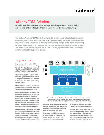
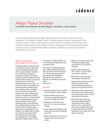
Allegro PSpice SimulatorFeaturesCadence simulation technology for PCBdesign integrates seamlessly with theCadence front-to-back PCB design flow,making it possible to have a single, u nifieddesign environment for both s imulationand PCB design.Analog ormixed-signalsimulator withprobe ulus creationAccess built-in functions that canbe described parametrically or drawpiecewise linear (PWL) signals freehandwith the mouse to create any shapestimulus. Create digital stimuli for signals,clocks, and buses; click-and-drag tointroduce and move transitions.Circuit simulationUsers can easily set up and run simulations, and then cross-probe simulationresults from Probe, an industry-standardwaveform viewer. Support for multiplesimulation profiles enables users to recalland run different simulations on the sameschematic. Simulation bias results can beviewed directly on the schematic includingnode voltages, device power calculations,and pin and subcircuit current. Supportfor Checkpoint Restart allows designersto reduce simulation times when thesame circuit is simulated multiple timeswith minor changes. Assertions enabledesigners to detect failure or warningconditions as the simulation progresses.Mixed analog/digital simulationIntegrated analog and event-driven digitalsimulations improve speed without lossof accuracy. A single graphical waveformanalyzer displays mixed analog and digitalsimulation results on the same time axis.Digital functions support five logic levelswww.cadence.comAllegro Design Entry HDLSymbolsfrom models,bias infoPCB layoutGerber/NC Drill,GenCAM/GenCAD,pick and place reportsVerifiednetlistsDE-HDLPart BrowserPart table fileAllegro PSpice Simulatoradvanced analysis- Smoke analysis- Sensitivity analysis- Optimizer- Monte Carlo analysisNetlist, stimuli,simulation settings,cross-probingPart ManagerInterfaceto part sAllegro PSpiceSimulatorModel EditorVendor modelsDesign entry and editingSelect from a library of more than 33,000symbols and models for simulation todesign with Cadence PCB schematicdesign entry technology. It providesmany features that allow you to easilycapture and simulate mixed-signaldesigns. Seamless integrations includeone-button simulation and cross-probing,and many other simulation utilities.Additionally, Allegro PSpice Simulatorincludes a syntax-aware Spice circuit filetext editor.DeviceequationsAllegro PSpiceSimulatorModel LibraryBSIM1, BSIM3,EKV modelsVariant EditorVerifiedBOMsPlace partPurchasing/inventoryPartsFabrication,assembly and testVariant reports for board assembly and BOMsReleased BOMsMRP/ERP/PDMsystemFigure 1: Allegro PSpice Simulatorand 64 strengths, load-dependent delays,and hazard/race checking. Allegro PSpiceSimulator also features propagationmodeling for digital gates and constraintchecking (such as setup and hold timing).Analog analysisExplore circuit behavior using DC,AC,noise, transient, parametersweeps,Monte Carlo, and DC sensitivityanalyses. Allegro PSpice Simulatorincludes interactive simulation controllersand two simulation solvers.Graphical results and data displayProbe Windows allows users to choosefrom an expanded set of mathematicalfunctions to apply to simulation outputvariables. Designers can create plot window t emplates and use them to easilymake complex measurements by simplyplacing markers directly on the desiredpins, nets, and parts in the schematic,as well as be able to view a continuousmarching waveform as simulationprogresses.The tools also enable users to measureperformance characteristics of a circuitusing built-in measurement functionsand creation of custom measurements.For data display, additional capabilitiesallow plotting of both real and complexfunctions of circuit voltage, current, andpower consumption, including Bodé plotsfor gain and phase margin and derivativesfor small-signal characteristics.(See Figure 2.) Annotate simulationresult using floating labels on the circuitvoltage, current, and power dissipationat time 0 for a circuit at each node in theschematic.ModelsIncluded are a large variety of accurateinternal models—which typically includetemperature effects—that add flexibilityto simulations. Models are available withR, L, C, and bipolar transistors plus: Modeling apps create a model withuser-input parameters (such as froma datasheet) and place a schematiccomponent automatically associatedwith the newly created model withouthaving to leave the OrCAD Capturecanvas. Built-in IGBTs Seven MOSFET models, including industry-standard BSIM3v3.2 andthe new EKV 2.6 model Five GaAsFET models, includingParker-Skellern and TriQuint TOM-2,TOM-3 models Nonlinear magnetic models completewith saturation and hysteresis2
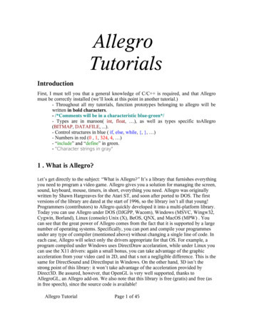
Allegro PSpice SimulatorNew behavioral capabilities includemathematical functions like in(x), exp(x),and sqrt(x).Magnetic parts editingFigure 2: Allegro PSpice Simulator provides a complete simulation environment includingsimulation waveform analysis with cross-probing and bias results displayed on the schematic Transmission line models thatincorporate delay, reflection, loss,dispersion, and crosstalk Digital primitives, including bi-directionaltransfer gates with analog I/O models Battery models allow accuratesimulation of the discharge cycle andoperating conditions Comprehensive model set for variouselectromechanical and mechanicaldevices like BLDC, flywheel, resolver,tacho, etc. Built-in library component forcommonly used mathematical functions Models for Tiny Switch-III family devicesand new Optocoupler devicesThe Device Model Interface capabilityin PSpice offers enables simulation ofsystem designs using different kinds ofabstractions. With the GUI, users candefine C/ C , System C, and Verilog Acomponents and simulate them in thesimulator.Model editingIt’s easy to extract a model of a supporteddevice type—simply enter the requireddata from the device’s datasheet. Onceyou have extracted, the PSpice ModelEditor automatically creates a part of themodel, making it available for immediateuse in the design.Behavioral modelingFunctional blocks are described usingmathematical expressions and functions,which allow designers to leverage a fullset of mathematical operators, nonlinearfunctions, and filters. Circuit behaviorcan be defined in the time or frequencydomain, by formula (including Laplacetransforms), or by look-up tables. Errorand warning messages can be specifiedin different conditions. Users can easilyselect parameters, which have beenpassed to subcircuits in a hierarchy, andinsert them into transfer functions.The Magnetic Parts Editor helps designersovercome issues involved in manuallydesigning transformers. Users can designmagnetic transformers and DC inductors,and generate simulation models for transformers and inductors that can then beused in Allegro PSpice Simulator circuits.The Magnetic Parts Editor also allowsdesigners to generate data requiredfor manufacturing the transformers or inductors. The manufacturer’s reportthat is generated by the PSpice MagneticDesigner after the completion of thedesign process contains the complete datarequired by a vendor to develop the transformer for commercial use. The modelingdesign capabilities help you generateaccurate PSpice models, including windingresistances and various parasitics.EncryptionThe encryption feature allows models tobe encrypted using 56-bit DES algorithm.SLPSCadence simulation technology and theMathWorks’ MATLAB Simulink packageintegrate two industry-leading simulationtools into a powerful co-simulation environment (SLPS). However, in orderto run PSpice SLPS one must have aPSpice SLPS license along with a PSpiceor Allegro PSpice Simulator license.Simulink is a platform for multi-domainsimulation and model-based design ofdynamic systems. The SLPS integrationallows designers to perform system-levelModel libraryUsers can select from more than 33,000analog and mixed-signal models ofdevices made in North America, Japan,and Europe. Also included are more than4,500 parameterized models for BJTs,JFETs, MOSFETs, IGBTs, SCRs, magneticcores and toroids, power diodes andbridges, operational amplifiers, optocouplers, regulators, PWM controllers, multipliers, timers, and sample-and-holds.www.cadence.comP(u)0(P) 2PolynomialSLPS-KRelay-K-heater or temperaturedaily temperaturevariation5/9Add1Gain232constantFigure 3: SLPS integration allows designers to interface the Allegro PSpice Simulator with Simulinkand then observe the waveforms after Simulink-Allegro PSpice Simulator co-simulation3
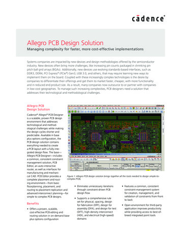
Allegro PSpice SimulatorOptimizerThe optimizer analyzes analog circuitsand systems, fine-tuning designs fasterthan trial-and-error bench testing. Ithelps find the best component values tomeet performance goals and constraints.Designers can use the optimizer toimprove design performance, updatedesigns to meet new specifications,optimize behavioral models for top-downdesign and model generation, and tune acircuit to match known results in the formof measurements or curves. The optimizerincludes three engines: modified leastsquares quadratic (LSQ), random, anddiscrete.SmokeFigure 4: Smoke compares simulated values with manufacturers’ limits to highlight devicesoperating outside safe operating rages.simulations that include realistic electricalmodels of actual components. Design andintegration problems can be discoveredmuch earlier in the design process,reducing the n umber of prototypesneeded to execute the design. SLPSintegration also lets designers of electromechanical systems—such as controlblocks, sensors, and power converters—perform integrated system and circuitsimulation.(See Figure 3.)Checkpoint restartThe checkpoint restart feature allowsthe designer to store simulation statesat various time-points and then restartsimulations from any of the simulationstates, which saves time. The designercan modify simulation settings and designparameters before starting a simulationfrom a pre-recorded time-state.Auto-convergence optionThis option makes the simulatorautomatically change tolerances limitsof c onvergence to make the design converge. Designers can use this optionto achieve convergence and thenwww.cadence.comfine-tune simulations by further modifyingsimulator options. This option is recommended for power electronic designs.Advanced analysis capabilitiesUsing advanced analysis capabilities,designers can automatically maximizethe performance of circuits. Four importantcapabilities—sensitivity analysis, optimization, Smoke (stress analysis), and MonteCarlo (yield analysis)—enable engineersto create virtual prototypes of designs andmaximize circuit performance automatically.Measurements across m ultiple simulationprofiles can be processed together.SensitivityThe sensitivity option identifies whichcomponent parameters are critical tothe goals of a circuit’s performanceby examining how each componentaffects circuit behavior by itself and incomparison to the other components.It allows designers to identify sensitivecomponents and export them to theoptimizer to fine-tune circuit behavior.The Smoke option warns of stressed components due to power dissipation,increases in junction temperature,secondary breakdowns, or violationsof voltage/current limits. Over time,these components can cause circuitfailure. Designers can use Smoke tocompare circuit simulation results to acomponent’s safe operating limits. Iflimits are exceeded, Smoke i dentifies theproblem parameters. It can also be usedfor creating, modifying, and configuringderate files for use with Smoke analysis.(See Figure 4.)Monte CarloMonte Carlo predicts the behaviorof a circuit statistically when partvalues are varied within their tolerancerange. Monte Carlo also calculatesyield, which can be used for massmanufacturing predictions. Use MonteCarlo for c alculating yield based on yourspecifications calculating statistical data,displaying results in a probability densityhistogram, and displaying results in acumulative distribution graph.4
Allegro PSpice SimulatorParametric plotterCadence Services and SupportOnce a circuit is created and simulated,the parametric plotter is used for s weeping multiple parameters. Any number of design and model parameters (in any combination) can be sweptand results viewed in tabular or plotform. Designers can use the parametricplotter for allowing device/model parameters to be swept, displaying sweepresults in spreadsheet format, allottingmeasurement results in probe UI, andevaluating post-analysis measurement. Cadence application engineers cananswer your technical questions bytelephone, email, or Internet—they canalso provide technical assistance andcustom trainingSystem Requirements Intel Core 2 Duo 2.66GHz or AMDAthlon 64 X2 5200 (Note: Fasterprocessors are preferred) Cadence certified instructors teachmore than 70 courses and bringtheir real-world experience into theclassroom More than 25 Internet LearningSeries (iLS) online courses allow youthe flexibility of training at your owncomputer via the Internet Cadence Online Support gives you 24x7online access to a knowledgebase ofthe latest solutions, technical documentation, software downloads, and more 8GB RAM 500GB free disk space 1280 x 1024 display resolution withtrue color (at least 32-bit color) For more information, please visitwww.cadence.com/support-andtraining Dedicated graphics card Single or dual monitors (for physicaldesign) Broadband internet connection forsome servicesCadence Design Systems enables global electronic design innovation and plays an essential role in thecreation of today’s electronics. Customers use Cadence software, hardware, IP, and expertise to designand verify today’s mobile, cloud, and connectivity applications. www.cadence.com 2016 All rights reserved worldwide. Cadence, the Cadence logo, and the other Cadence marks found at www.cadence.com/go/trademarksare trademarks or registered trademarks of Cadence Design Systems, Inc. SystemC is a trademark of Accellera Systems Initiative Inc. All othertrademarks are the property of their respective owners.7457 10/16 SA/JT/PDF
Allegro PSpice Simulator Features Cadence simulation technology for PCB design integrates seamlessly with the Cadence front-to-back PCB design flow, making it possible to have a single, unified design environment for both simulation and PCB design. Design entry and editing Select from a library of more than 33,000