Transcription
SUBCOURSEAL0926EDITIONABASICHYDRAULIC SYSTEMSAND COMPONENTS
BASIC HYDRAULIC SYSTEMS AND COMPONENTSSubcourse Number AL 0926EDITION AUS Army Aviation Logistics SchoolFort Eustis, Virginia 23604-54394 Credit HoursEdition Date: September 1994SUBCOURSE OVERVIEWThis subcourse is designed to provide instruction on the concept and operation of the basic componentsof the hydraulic system. It also describes the various components of a typical hydraulic system, theirconstruction and functions, and their relationship to each other.When the term hydraulics is applied to aircraft, it means a method of transmitting power from onelocation to another through the use of a confined fluid. The functions performed by hydraulic systems inaircraft include assisting in flight control, extending and retracting landing gear, positioning flaps,operating hoists, raising and lowering cargo doors, and starting engines.The hydraulic systems used in Army aircraft are dependable and relatively trouble-free.maintenance requirements are small in comparison to the work the system performs.iTheAL0926
This subcourse is to be completed on a self-study basis. You will grade your lessons as you completethem using the lesson answer keys which are enclosed. If you have answered any question incorrectly,study the question reference shown on the answer key and evaluate all possible solutions.There are no prerequisites for this subcourse.This subcourse reflects the doctrine which was current at the time it was prepared. In your own worksituation, always refer to the latest official publications.Unless otherwise stated, the masculine gender of singular pronouns is used to refer to both men andwomen.TERMINAL LEARNING OBJECTIVEACTION:You will demonstrate a knowledge of the basic components of the hydraulic system,including the devices which actuate, discharge, and control the flow of hydraulic fluidand those devices which sense, control, and limit hydraulic pressure.CONDITIONS:You will use the material in this subcourse.STANDARD:You must correctly answer 70 percent of the questions on the subcourse examinationto pass this subcourse.iiAL0926
TABLE OF CONTENTSSectionPageSubcourse Overview .iTerminal Learning Objective.iiAdministrative Instructions .ivGrading and Certification Instructions .ivLesson 1: Hydraulic Reservoirs, Filters, Pumps,Accumulators, and Motors .1Practice Exercise .19Answer Key and Feedback .22Lesson 2: Basic Construction and Operation of HydraulicActuating Devices, Flow Control, and DirectionalDevices.25Practice Exercise .43Answer Key and Feedback .46Lesson 3: Hydraulic Pressure-Limiting, Controlling, andSensing Devices .49Practice Exercise .55Answer Key and Feedback .58Examination .61Appendix: Glossary .69Student Inquiry SheetsiiiAL0926
GRADING AND CERTIFICATION INSTRUCTIONSExamination: This subcourse contains a multiple-choice examination covering the material contained inthis subcourse. After studying the lessons and working through the practice exercises, complete theexamination. Mark your answers in the subcourse booklet, then transfer them to the ACCP ExaminationResponse Sheet. Completely black out the lettered oval which corresponds to your selection (A, B, C,or D). Use a number 2 lead pencil to mark your responses. When you complete the ACCP examinationresponse sheet, mail it in the preaddressed envelope you received with this subcourse. You will receivean examination score in the mail. You will receive Four credit hours for successful completion of thisexamination.ivAL0926
LESSON 1HYDRAULIC RESERVOIRS, FILTERS, PUMPS, ACCUMULATORS, AND MOTORSSTP Tasks: 552-758-1063552-758-1071OVERVIEWLESSON DESCRIPTION:In this lesson you will learn the basic operation of the hydraulic reservoirs, filters, pumps, accumulators,and motors.TERMINAL LEARNING OBJECTIVE:ACTION:After this lesson you will demonstrate knowledge of hydraulic reservoirs, filters,pumps, accumulators, and motors.CONDITIONS:You will study the material in this lesson in a classroom environment or at yourhome.STANDARD:You will correctly answer all the questions in the practice exercise before youproceed to the next lesson.REFERENCES: The material contained in this lesson was derived from the following publications:AR 310-25, AR 310-50, FM 1-500, FM 1-509, TM 1-1500-204-23 Series, TM 551510-Series (Fixed Wing Maintenance Manuals), TM 55-1520-Series (Rotary wingMaintenance Manuals) and TM 4301A 05 0267 (Air Force)1AL0926
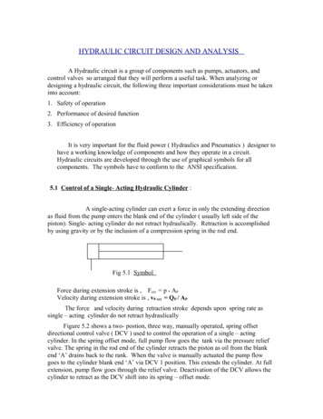
INTRODUCTIONA means of storing hydraulic fluid and minimizing contamination is necessary to any aircraft hydraulicsystem. These functions are performed by reservoirs and filters. The component which causes fluidflow in a hydraulic system--the heart of any hydraulic system--can be a hand pump, power-driven pump,accumulator, or any combination of the three. Finally, a means of converting hydraulic pressure tomechanical rotation is sometimes necessary, and this is accomplished by a hydraulic motor.HYDRAULIC RESERVOIRSThe hydraulic reservoir is a container for holding the fluid required to supply the system, including areserve to cover any losses from minor leakage and evaporation. The reservoir can be designed toprovide space for fluid expansion, permit air entrained in the fluid to escape, and to help cool the fluid.Figure 1-1 shows two typical reservoirs. Compare the two reservoirs item by item and, except for thefilters and bypass valve, notice the similarities.Filling reservoirs to the top during servicing leaves no space for expansion. Most reservoirs aredesigned with the rim at the filler neck below the top of the reservoir to prevent overfilling. Somemeans of checking the fluid level is usually provided on a reservoir. This may be a glass or plastic sightgage, a tube, or a dipstick. Hydraulic reservoirs are either vented to the atmosphere or closed to theatmosphere and pressurized. A description of each type follows.Vented Reservoir. A vented reservoir is one that is open to atmospheric pressure through a vent line.Because atmospheric pressure and gravity are the forces which cause the fluid to flow to the pump, avented reservoir is mounted at the highest point in the hydraulic system. Air is drawn into andexhausted from the reservoir through a vent line. A filter is usually installed in the vent line to preventforeign material from being taken into the system.Pressurized Reservoir. A pressurized reservoir is sealed from the atmosphere. This reservoir ispressurized either by engine bleed air or by hydraulic pressure produced within the hydraulic systemitself. Pressurized reservoirs are used on aircraft intended for high altitude flight, where atmosphericpressure is not enough to cause fluid flow to the pump.In reservoirs pressurized by engine bleed air, the amount of air pressure is determined by an airpressure regulator--usually 10 to 15 pounds per square inch (psi) gage. An example of a2AL0926
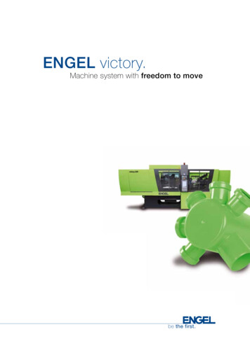
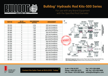
hydraulically pressurized reservoir used in the CH-47 hydraulic system is shown in Figure 1-2.This reservoir, or tank as it is referred to by Boeing-Vertol, is constructed of a metal housing withtwo internal pistons, one fixed and the other a floating piston which slides along a central tube.Attached to the floating piston is a larger tube that projects through the forward end of the tank and iscalibrated to indicate FULL and REFILL fluid levels for ramp-up and ramp-down positions.Figure 1-1. Typical Hydraulic Reservoirs.Hydraulic fluid at 3,000 psi flows into the central tube as shown in Figure 1-2, passes through twooutlet holes, and applies pressure at the piston area between the two tubes. Because the smaller pistonhas a .5-square-inch (sq in) exposed surface and the floating piston has a 30-sq-in exposed surface, the3,000-psi pressure acting upon the smaller forward area produces an opposing pressure of 50 psi on thereturn fluid stored at the rear of the piston.3AL0926
Additional Reservoir Components. Many reservoirs, as shown in Figure 1-1, are constructed withbaffles or fins to keep the fluid from swirling and foaming. Foaming can cause air to become entrainedin the system.Filters are incorporated in some reservoirs to filter the fluid before it leaves the reservoir.A bypass valve is used to ensure that the pump does not starve if the filter becomes clogged.A standpipe is used in a reservoir which supplies a normal and an emergency system. The mainsystem draws its fluid from the standpipe, which is located at a higher elevation. This ensures anadequate fluid supply to the secondary system if the main system fails.Figure 1-2. Hydraulic Reservoir Pressurized With Hydraulic Fluid.HYDRAULIC FILTERContamination of hydraulic fluid is one of the common causes of hydraulic system troubles. Installingfilter units in the pressure and return lines of a hydraulic system allows4AL0926
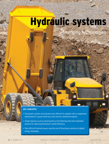
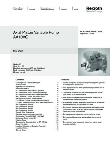
contamination to be removed from the fluid before it reaches the various operating components. Filtersof this type are referred to as line filters.Line Filter Construction. A typical line filter is shown in Figure 1-3. It has two major parts--thefilter case, or bowl, and the filter head. The bowl holds the head that screws into it. The head has aninlet port, outlet port, and relief valve. Normal fluid flow is through the inlet port, around the outside ofthe element, through the element to the inner chamber, and out through the outlet port. The bypassvalve lets the fluid bypass the filter element if it becomes clogged.Figure 1-3. Typical Line Filter Assembly.Types of Filter Elements. The most common filtering element used on Army aircraft is the micronictype. It is a disposable unit made of treated cellulose and is formed into accordion pleats, as shown inFigure 1-3. Most filter elements are5AL0926
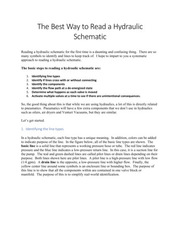
capable of removing all contaminants larger than 10 to 25 microns (1 micron equals 0.00004 inch).Another type is the cuno filter element. It has a stack of closely spaced disks shaped like spokedwheels. The hydraulic fluid is filtered as it passes between the disks.HAND-OPERATED HYDRAULIC PUMPThe heart of any hydraulic system is the pump which converts mechanical energy into hydraulic energy.The source of mechanical energy may be an electric motor, the engine, or the operator's muscle.Pumps powered by muscle are called hand pumps. They are used in emergencies as backups for powerpumps and for ground checks of the hydraulic system. The double-action hand pump produces fluidflow with every stroke and is the only type used on Army aircraft.Handle to the Right. The double-action hand pump, shown in Figure 1-4, consists of a cylinderpiston with built-in check valve, piston rod, operating handle, and a check valve built into the inlet port.As the handle is moved to the right, the piston and rod also move to the right. On this stroke, the inletcheck valve opens as a result of the partial vacuum caused by the movement of the piston, allowing fluidto be drawn into the left chamber. At the same time, the inner check valve closes. As the piston movesto the right, the fluid in the right chamber is forced out into the system.Figure 1-4. Double-Action Hand Pump.6AL0926
Handle to the Left. When the handle is moved to the left, the piston and rod assembly also move tothe left. The inlet check valve now closes, preventing the fluid in the left chamber from returning to thereservoir. At the same time, the pistonhead check valve opens, allowing the fluid to enter the rightchamber.Fluid Into the System. The pump produces pressure on both strokes because of the difference involume between the right and left chambers. The piston rod takes up a good share of the space in theright chamber. Therefore, the excess fluid is forced out of the pump and into the hydraulic system,creating fluid pressure.PUMP-DRIVEN HYDRAULIC PUMPSPower-driven pumps receive their driving force from an external power source, such as the aircraftengine. This force is converted into energy in the form of fluid pressure. The four basic types of powerdriven hydraulic pumps are gear, vane, diaphragm, and piston. Of these, the piston type is mostcommonly found in Army aircraft. The reason for this is that it operates more efficiently at higherpressures and has a longer life than any of the others. Piston pumps are further categorized as eitherconstant delivery or variable delivery.Pumps are coupled to their driving units by a short, splined coupling shaft, commonly called a drivecoupling. As shown in Figure 1-5, the shaft is designed with a weakened center section called a shearsection, with just enough strength to run the pump under normal circumstances. Should some troubledevelop within the pump causing it to turn unusually hard, the shear section will break. This preventsdamage to the pump or driving unit.Figure 1-5. Pump Drive Coupling.Constant-delivery piston pumps deliver a given quantity of fluid per revolution of the drive coupling,regardless of pressure demands. The quantity of fluid delivered per minute depends on7AL0926
pump revolutions per minute (rpm). In a system requiring constant pressure, this type of pump must beused with a pressure regulator. The two types of constant-delivery piston pumps used in Army aircraftare the angular and cam.Angular Piston Pump Construction. The basic components of an angular piston pump are shown inFigure 1-6. They are- (1) A rotating group consisting of a coupling shaft, universal link, connecting rods, pistons,and cylinder block. (2) A stationary group consisting of the valve plate and the pump case or housing.The cylinder bores lie parallel to, and are evenly spaced around, the pump axis. For this reason, apiston pump is often referred to as an axial piston pump.Packings on seals are not required to control piston-to-bore leakage. This is controlled entirely byclose machining and accurate fit between piston and bore. The clearance is only enough to allow forlubrication by the hydraulic fluid and slight expansion when the parts become heated. Pistons areindividually fitted to their bores during manufacture and must not be changed from pump to pump orbore to bore.Pump Operation. As the coupling shaft is turned by the pump power source, the pistons and cylinderblock turn along with it because they are interconnected. The angle that exists between the cylinderblock and coupling shaft causes the pistons to move back and forth in their respective cylinder bores asthe coupling is turned: During the first half of a revolution of the pump, a cylinder is aligned with the inlet port inthe valve plate. At this time the piston is moving away from the valve plate and drawinghydraulic fluid into the cylinder. During the second half of the revolution, the cylinder islining up with the outlet port in the valve plate. At this time, the piston is moving toward thevalve plate, thus causing fluid previously drawn into the cylinder to be forced out through theoutlet port. Fluid is constantly being drawn into and expelled out of the pump as it turns. This provides amultiple overlap of the individual spurts of fluid forced from the cylinders and results indelivery of a smooth, nonpulsating flow of fluid from the pump.8AL0926
Cam-Piston Pumps. A cam is used to cause the stroking of the pistons in a cam-piston pump. Twovariations are used: in one the cam rotates and the cylinder block is stationary, and in the other the camis stationary and the cylinder block rotates. Both cam-piston pumps are described below:Figure 1-6. Typical Angular Piston Pump. Rotating-cam pump. The rotating-cam pump is the one most commonly used in Armyaviation. As the cam turns in a rotating-cam pump (Figure 1-7), its high and low points passalternately and in turn under each9AL0926
piston. It pushes the piston further into its bore, causing fluid to be expelled from the bore. When thefalling face of the cam comes under a piston, the piston's return spring pulls the piston down in its bore.This causes fluid to be drawn into the bore.Each bore has a check valve that opens to allow fluid to be expelled from the bore by the piston'smovement. These valves are closed by spring pressure during inlet strokes of the pistons. This fluid isdrawn into the bores only through the central inlet passages. The bores only through the central inletpassages. The movement of the pistons in drawing in and expelling fluid is overlapping, resulting in anonpulsating fluid flow.Figure 1-7. Typical Rotating-Cam Piston Pump. Stationary-cam pump. The operation and construction of a stationary-cam pump areidentical to that of the rotating cam except that the cylinder block turns, not the cam. Thestationary-cam pump is not used on the Army's OV-1, AH-1G, and UH-1C.10AL0926
VARIABLE-DELIVERY PISTON PUMPSA variable-delivery piston pump automatically and instantly varies the amount of fluid delivered to thepressure circuit of a hydraulic system to meet varying system demands. This is accomplished by using acompensator, which is an integral part of the pump. The compensator is sensitive to the amount ofpressure present in the pump and in the hydraulic system pressure circuit. When the circuit pressurerises, the compensator causes the pump output to decrease.Conversely, when circuit pressure drops, the compensator causes pump output to increase. There aretwo ways of varying output--demand principle (cam) and stroke-reduction principle (angular).Demand Principle. The demand principle (Figure 1-8) is based on varying pump output to fill thesystem's changing demands by making the piston stroke effective in varying degrees.Figure 1-8. Variable-Delivery Demand-Principle Cam Pump.11AL0926
The pistons are designed with large hollow centers. The centers are intersected by cross-drilledrelief holes that open into the pump case. Each piston is equipped with a movable sleeve, which canblock the relief holes. When these holes are not blocked, fluid displaced by the pistons is dischargedthrough the relief holes into the pump case, instead of past the pump check valves and out the outletport.When full fluid flow is required, the sleeves are positioned to block the relief holes for the entirelength of piston stroke. When zero flow is required, the sleeves are positioned not to block the flowduring any portion of the piston stroke. For requirements between zero and full flow, the relief holes areuncovered or blocked accordingly.The sleeves are moved into their required positions by a device called a pump compensator piston.The sleeves and compensator piston are interconnected by means of a spider. Fluid pressure for thecompensator piston is obtained from the discharge port (system pressure) through a control orifice.Stroke-Reduction Principle. The stroke-reduction principle (Figure 1-9) is based on varying theangle of the cylinder block in an angular pump. This controls the length of the piston's stroke and thusthe volume per stroke.The cylinder block angle change is achieved by using a yoke that swivels around a pivot pin called apintle. The angle is automatically controlled by using a compensator assembly consisting of a pressurecontrol valve, pressure-control piston, and mechanical linkage that is connected to the yoke.As system pressure increases, the pilot valve opens a passageway allowing fluid to act on the controlpiston. The piston moves, compressing its spring, and through mechanical linkage moves the yoketoward the zero flow (zero angle) position. As system pressure decreases, the pressure is relieved on thepiston, and its spring moves the pump into the full flow position.HYDRAULIC ACCUMULATORSThe purpose of a hydraulic accumulator is to store hydraulic fluid under pressure. It may be used to--: Dampen hydraulic shocks which may develop when pressure surges occur in hydraulic systems. Add to the output of a pump during peak load operation of the system, making it possible to usea pump of much smaller capacity than would otherwise be required.12AL0926
Absorb the increases in fluid volume caused by increases in temperature. Act as a source of fluid pressure for starting aircraft auxiliary power units (APUs). Assist in emergency operations.Figure 1-9. Variable Stroke-Reduction Pump.13AL0926
Accumulators are divided into types according to the means used to separate the air fluid chambers;these are the diaphragm, bladder, and piston accumulators.Diaphragm Accumulator. The diaphragm accumulator consists of two hollow, hemispherical metalsections bolted together at the center. Notice in Figure 1-10 that one of the halves has a fitting to attachthe unit to the hydraulic system; the other half is equipped with an air valve for charging the unit withcompressed air or nitrogen. Mounted between the two halves is a synthetic rubber diaphragm thatdivides the accumulator into two sections. The accumulator is initially charged with air through the airvalve to a pressure of approximately 50 percent of the hydraulic system pressure. This initial air chargeforces the diaphragm upward against the inner surface of the upper section of the accumulator.Figure 1-10. Diaphragm Accumulator.When fluid pressure increases above the initial air charge, fluid is forced into the upper chamberthrough the system14AL0926
pressure port, pushing the diaphragm down and further compressing the air in the bottom chamber.Under peak load, the air pressure in the lower chamber forces fluid back into the hydraulic system tomaintain operating pressure. Also, if the power pump fails, the compressed air forces a limited amountof pressurized fluid into the system.Bladder Accumulator. The bladder accumulator operates on the same principle and for the samepurpose as the diaphragm accumulator but varies in construction, as shown in Figure 1-11. The unit is aone-piece metal sphere with a fluid pressure inlet at the top and an opening at the bottom for insertingthe bladder. A large screw-type plug at the bottom of the accumulator is a retainer for the bladder thatalso seals the unit. A high-pressure air valve is also incorporated in the retainer plug. Fluid entersthrough the system pressure port. As fluid pressure increases above the initial air charge of theaccumulator, it forces the bladder downward against the airFigure 1-11. Bladder Accumulator.15AL0926
charge, filling the upper chamber with fluid pressure. The broken lines in Figure 1-11 indicate theapproximate position of the bladder at the time of the initial air charge.Piston Accumulator. The piston accumulator serves the same purpose and operates by the sameprinciples as do the diaphragm and bladder accumulators. As shown in Figure 1-12, the unit consists ofa cylinder and piston assembly with ports on each end. Fluid pressure from the system enters the leftport, forcing the piston down against the initial air charge in the right chamber of the cylinder. A highpressure air valve is located at the right port for charging the unit. A drilled passage from the fluid sideof the piston to the outside of the piston provides lubrication between the cylinder walls and the piston.Figure 1-12. Piston Accumulator.HYDRAULIC MOTORSHydraulic motors are installed in hydraulic systems to use hydraulic pressure in obtaining poweredrotation. A hydraulic motor does just the opposite of what a power-driven pump does. A pump receivesrotative force from an engine or other driving unit and converts it into hydraulic pressure. A hydraulicmotor receives hydraulic fluid pressure and converts it into rotative force.Figure 1-13 shows a typical hydraulic motor. The two main ports through which fluid pressure isreceived and return fluid is discharged are marked A and B, respectively. The motor has a cylinderblock-and-piston assembly in which the bores and pistons are in axial arrangement, the same as in ahydraulic pump. Hydraulic motors can be instantly started, stopped, or reversed under any degree ofload; they can be stalled by16AL0926
overload without damage. The direction of rotation of a hydraulic motor can be changed by reversingthe flow of fluid into the ports of the motor.Figure 1-13. Typical Hydraulic Motor.SUMMARYThe basic components of any hydraulic system are reservoirs, filters, and pumps (hand or power-driven).The reservoir holds the fluid supply for the system and helps cool the fluid. Filters are used to ensurethat no contamination reaches the components in a hydraulic system. The pleated micronic filter is themost common.The pump converts mechanical energy to fluid flow. The most common power-driven pump is thepiston pump. In all but the simplest hydraulic systems, variable-delivery pumps are used. A variabledelivery pump delivers only the amount of fluid demanded by the system. This is accomplished throughthe use of a compensator.Depending on the type of aircraft, hydraulic accumulators and hydraulic motors can also be found in thesystem. Accumulators are used primarily to supply pressure for starting auxiliary power units andemergency hydraulic pressure. Hydraulic motors perform a variety of functions, including raising andlowering cargo doors, operating rescue hoists, and positioning wing flaps.17AL0926
THIS PAGE IS INTENTIONALLY LEFT BLANK.18AL0926
LESSON 1PRACTICE EXERCISEThe following items will test your grasp of the material covered in this lesson. There is only one correctanswer for each item. When you have completed the exercise, check your answers with the answer keythat follows. If you answer any item incorrectly, study again that part of the lesson which contains theportion involved.1.The pistons and cylinder block rotate at what RPM?A. The same.B. 500 RPM.C. 750 RPM.D. 1500 RPM.2.How many types of hydraulic reservoirs are there?A. One.B. Two.C. Three.D. Four.3.The stationary-cam pump is NOT used on what three Army aircraft?A. UH-1H, AH-1S, and OV-1B.B. UH-1D, AH-1H, and OV-1.C. OV-1A, AH-1G, and UH-1E.D. OV-1, AH-1G, and UH-1C.4.What type of pump is often used in Army aviation?A. Piston pump.B. Rotating-cam pump.C. Demand-principle compensator pump.D. Rotating-compensator pump.5.What is used to control piston-to-bore leakage in piston pumps?A. Wiper rings.B. O-rings.C. Seals.D. Close machining.19AL0926
THIS PAGE IS INTENTIONALLY LEFT BLANK.20AL0926
6.What type hydraulic pump would you most likely find on an Army AH-1?A. Compensator pump.B. Drive pump.C. Piston pump.D. Auxiliary pump.7.The angular pump uses what type of compensator?A. Stroke-reduction.B. Reduction-stroke.C. Cam-reduction.D. Piston-reduction.8.What component in a hydraulic system protects against pressure surges?A. Double-check valve.B. Stationary-cam pump.C. Accumulator.D. Hand-operated pump.9.What type of pump has a check valve built into the piston?A. Double-action hand pump.B. Single-action hand pump.C. Single-action cam pump.D. Double-action cam pump.10.What valve opens as the handle is moved to the right?A. Double check valve.B. Single check valve.C. Outlet check valve.D. Inlet check valve.21AL0926
LESSON 1PRACTICE EXERCISEANSWER KEY AND FEEDBACKItemCorrect Answer and Feedback1.A.The same RPM.Both operate alike because they are connected. (Page 8)2.B.2.The two types of reservoirs are classified as vented and pressurized. (Page 2)3.D.OV-l, AH-1G, and UH-1C.All Army aircraft do not have the stationary-cam pump as an operating component. (Page10)4.B.Rotating-cam pump.More Army aircraft use the rotating-cam pump than any type. (Page 9)5.D.Close machining.The piston and bore fit so closely that no other component is necessary to stop leakage.(Page 8)6.C.Piston pump.The Army has selected the most efficient, longest-lasting hydraulic pump to be used on itsaircraft. (Page 7)7.A.Stroke-reduction principle.The length of the stroke can be controlled by angling the cylinder block. (Page 12)8.C.Accumulator.The accumulator can absorb increases in fluid volume to prevent damage to the system.(Page 12)22AL0926
9.A.Double-action hand pump.The double-action hand pump has two check valves which allow fluid to be drawn into theleft and right chambers. (Page 6)10.D.Inlet check valve.Moving the handle to the right results in a slight vacuum, which opens the inlet check valveas a result of the partial vacuum caused by the movement of the piston, allowing fluid to bedrawn into the left chamber. (Page 6)23AL0926
THIS PAGE IS INTENTIONALLY LEFT BLANK.24AL0926
LESSON 2BASIC CONSTRUCTION AND OPERATION OF HYDRAULICACTUATING DEVICES, FLOW CONTROL, AND DIRECTIONAL DEVICESSTP Tasks: 552-758-1003552-758-1071OVERVIEWLESSON DESCRIPT
of the hydraulic system. It also describes the various components of a typical hydraulic system, their construction and functions, and their relationship to each other. When the term hydraulics is applied to aircraft, it means a method of transmitting power from one