Transcription
HP Virtual Connect Ethernet Cookbook:Single and Multi Enclosure Domain (Stacked)ScenariosPart number 603028-003Third edition August 2010
Copyright 2009,2010 Hewlett-Packard Development Company, L.P.The information contained herein is subject to change without notice. The only warranties for HP products and services are set forth in the expresswarranty statements accompanying such products and services. Nothing herein should be construed as constituting an additional warranty. HPshall not be liable for technical or editorial errors or omissions contained herein.Confidential computer software. Valid license from HP required for possession, use or copying. Consistent with FAR 12.211 and 12.212,Commercial Computer Software, Computer Software Documentation, and Technical Data for Commercial Items are licensed to the U.S.Government under vendor’s standard commercial license.Microsoft, Windows, and Windows Server are U.S. registered trademarks of Microsoft Corporation. Intel, Pentium, and Itanium are trademarksor registered trademarks of Intel Corporation or its subsidiaries in the United States and other countries. UNIX is a registered trademark of TheOpen Group.Intended audienceThis document is for the person who installs, administers, and troubleshoots HP BladeSystem servers with Virtual Connect. HP assumes you arequalified in the servicing of computer equipment and trained in recognizing hazards in products with hazardous energy levels.
ContentsPurpose . 6Introduction to Virtual Connect . 7Tunneled VLAN and Mapped VLANS . 9Chapter 1: Single Domain/Enclosure Scenarios . 12Overview . 12Requirements . 12Scenario 1:1 – Simple vNet with Active/Standby Uplinks and Optional Link Aggregation 802.3ad (LACP) Windows . 13Overview . 13Requirements . 13Installation and configuration . 15Switch configuration . 15Optionally Configuring Additional Uplinks to a vNet (LACP). 20Switch configuration . 21Summary. 23Results . 23Scenario 1:2 – Multiple Simple Networks with Active\Active Uplinks and Optional Link Aggregation 802.3ad(LACP) - Windows . 26Overview . 26Requirements . 26Installation and configuration . 28Optionally Configuring Additional Uplinks to a vNet (LACP). 32Summary. 38Results . 38Scenario 1:3 – Multiple Simple Networks Providing Redundancy and Link Aggregation 802.3ad (LACP) with VLANTunneling – VMware ESX . 40Overview . 40Requirements . 40Configuring Uplinks to a vNet (LACP). 40Installation and configuration . 42Summary. 49Results . 49Scenario 1:4 – VLAN Tagging (802.1Q) with a Shared Uplink Set (SUS) with Link Aggregation using LACP(802.3ad) – Windows . 52Overview . 52Requirements . 52Configuring Uplinks to a vNet (LACP). 52Installation and configuration . 54Summary. 60Results . 60Scenario 1:5 – VLAN Tagging (802.1Q) with a Shared Uplink Set (SUS) with Link Aggregation using LACP(802.3ad) – VMware ESX . 62Overview . 62Requirements . 62Contents3
Configuring Uplinks to a vNet (LACP). 62Installation and configuration . 64Summary. 70Results . 71Scenario 1:6 – VLAN Tagging (802.1Q) with Multiple Shared Uplink Sets (SUS) and Link Aggregation using LACP(802.3ad) – VMware ESX . 73Overview . 73Requirements . 73Configuring Uplinks to a vNet (LACP). 73Installation and configuration . 75Summary. 84Results . 85Scenario 1:7 – Private Networks (Simple vNet) . 88Overview . 88Requirements . 88Installation and configuration . 90Summary. 95Results . 95Chapter 2: Flex-10 Scenario . 98Overview . 98Requirements . 98Scenario 2:1 - Flex-10 - VLAN Tagging (802.1Q) with Multiple Shared Uplink Sets (SUS) and Mapped VLANs Windows 2003/2008 . 100Overview . 100Requirements . 100Installation and configuration . 102Summary. 109Result . 109Adding additional NICs to an existing server Profile . 116Summary. 119Result . 119Scenario 2:2 - Flex-10 - VLAN Tagging (802.1Q) with Multiple Shared Uplink Sets (SUS) and Mapped VLANs Windows 2008 Hyper-V . 122Overview . 122Requirements . 123Installation and configuration . 124Summary. 133Result . 133Scenario 2:3 - Flex-10 - VLAN Tagging (802.1Q) with Multiple Shared Uplink Sets (SUS) and Mapped VLANs - ESX4 . 140Overview . 140Requirements . 141Installation and configuration . 142Summary. 151Result . 151Scenario 2:4 - Flex-10 - VLAN Tagging (802.1Q) with Multiple Shared Uplink Sets (SUS) and Tunneled VLANs - ESX4 . 155Overview . 155Requirements . 156Installation and configuration . 157Contents4
Summary. 165Result . 166Chapter 3: Multi-Enclosure (Stacking) Scenarios . 170Overview . 170Requirements . 170Scenario 3:1 – Multi-Enclosure stacking, with Multiple Simple vNets, Redundant Uplinks and LACP (2 Enclosures). 171Overview . 171Requirements . 171Installation and configuration . 173Summary. 180Results . 181Scenario 3:2 - Flex-10 with Multi-Enclosure stacking - VLAN Tagging (802.1Q) with Multiple Shared Uplink Sets(SUS) - VMware ESX - (4 Enclosures) . 183Overview . 183Requirements . 184Installation and configuration . 186Summary. 199Result . 199Appendix A: Scenario-based Cisco command line reference . 203Appendix B: Scenario-based ProCurve command line reference . 214Appendix C: Acronyms and abbreviations . 224Appendix D: Useful VC CLI Command sets . 226Contents5
PurposeThe purpose of this Virtual Connect Cookbook is to provide new users to Virtual Connect with a betterunderstanding of the concepts and steps required when integrating HP BladeSystem and Virtual Connectcomponents into an existing network.The scenarios in this Cookbook vary from simplistic to more complex while covering a range of typicalbuilding blocks to use when designing Virtual Connect solutions. Although these scenarios are shownindividually, some scenarios could be combined to create a more complex and versatile Virtual Connectenvironment, however, keeping in mind the difference between mapped and tunneled VLANs, discussedlater in this paper are mutually exclusive.This is not meant to be a complete or detailed guide to Virtual Connect, but is intended to provide thereader with some valid examples of how Virtual Connect could be deployed. Many additionalconfigurations or scenarios could also be implemented.Purpose6
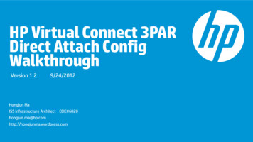
Introduction to Virtual ConnectVirtual Connect is an industry standard-based implementation of server-edge virtualization. It puts anabstraction layer between the servers and the external networks so the LAN and SAN see a pool ofservers rather than individual servers (Figure 1). Once the LAN and SAN connections are physically madeto the pool of servers, the server administrator uses Virtual Connect management tools (Virtual ConnectEnterprise Manager or Virtual Connect Manager) to create an Interconnect modules connection profile foreach server.Additional Virtual Connect Reference MaterialLink to HP Virtual Connect technology for the HP BladeSystem c-Class, 2nd edition when /SupportManual/c00814156/c00814156.pdfLink to HP Virtual Connect for c-Class BladeSystem Setup and Installation ort/SupportManual/c01732252/c01732252.pdfLink to HP Flex-10 ual Connect Fibre Channel CookbookVirtual Connect can be used to support both Ethernet and Fibre Channel connections; however, this guideis focused completely on the Ethernet configuration.For Fibre Channel connectivity, please refer to the Virtual Connect Fibre Channel p.com/go/blades)Virtual Connect 2.30 Firmware ReleaseShared Uplink Sets provide administrators the ability to distribute VLANs into discrete and definedEthernet Networks (vNet.) These vNets can then be mapped logically to a Server Profile NetworkConnection allowing only the required VLANs to be associated with the specific server NIC port. Thisalso allows the flexibility to have various network connections for different physical Operating Systeminstances (i.e. VMware ESX host and physical Windows host.)Virtual Connect firmware 2.30 was released in September 2009 and provided a number of new features.Among those feature enhancements are a couple which are relevant to this paper; DCC (Device Control Channel), which adds support for link state, notification and dynamicbandwidth allocation for Flex-10 NICs. DCC provides the ability to dynamically edit or modify a Flex-10 profile, renaming the Flex-10profile, editing NIC connections within a profile and/or adjusting link speed without the need for aserver power down or rebootNote: in order to obtain the full functionality of DCC, NC532i/m NIC firmware level must be2.2.3 or later.Introduction to Virtual Connect 7
The following Shared Uplink Set rules apply per domain: 320 Unique VLANs per Virtual Connect Ethernet module128 Unique VLANs per Shared Uplink Set28 Unique Server Mapped VLANs per Server Profile Network ConnectionPlease see the Virtual Connect 2.30 Release Notes for future details on these and other new features.Introduction to Virtual Connect 8
Tunneled VLAN and Mapped VLANSVirtual Connect provides two Ethernet networks connection methods. Both of these connection types arediscussed within the following scenarios.vNetA vNet is a term used to describe a network within Virtual Connect. A vNet could represent a dedicatednetwork within Virtual Connect, in which case it would operate in one of two modes, the first is a simplevNet that will pass untagged frames. The second is a vNet tunnel which will pass tagged frames for one ormany VLANs. An individual “Network” as configured within a Shared Uplink Set, which would define aspecific VLAN, is also vNet.The vNet is a network connection between one or many server NICs to one or many uplink ports. A vNetcould also exist without uplink ports, to provide connectivity between server NICs within an enclosure to forlocal only communications such as, cluster a heartbeat network.A vNet could be used to connect a single VLAN, no tagging, to one or many server NICs. If this network ispart of a VLAN, by configuring the upstream switch port as an access or untagged port, by extension, anyserver connected to this vNet would reside in that VLAN, but would not need to be configured to interpretthe VLAN tags. A tunneled vNet will pass VLAN tagged frames, without the need to interpret or forwardthose frames based on the VLAN tag. Within a tunneled vNet the VLAN tag is completely ignored byVirtual Connect and the frame is forwarded to the appropriate connection (server NIC[s] or uplinks)depending on frame direction flow. In this case, the end server would need to be configured to interpretthe VLAN tags. This could be a server with a local operating system, in which the network stack wouldneed to be configured to understand which VLAN the server was in, or a virtualization host with a vSwitchsupporting multiple VLANs.The tunneled vNet has no limit to the number of VLANs it can support.Benefits of a vNetIf no VLAN support is required, support for a single specific VLAN being presented as untagged or manyVLANs need to be presented to the server a vNet is a very simple network to configure and manage withinVirtual Connect.A vNet can be utilized in one of two ways, a simple vNet, used to pass untagged frames and a tunneledvNet. A tunneled vNet can be used to pass many VLANs without modifying the VLAN tags, functioning asa transparent VLAN Pass-Thru module.Shared Uplink Set (SUS)The SUS provides the ability to support VLAN tagging and forward frames based on the VLAN tags of thoseframes. The SUS connects one or many server NICs to one or many uplink ports. A SUS would beconfigured for the specific VLANs it will support. If support for additional VLANs is required, those VLANsneed to be configured within the SUS.When connecting a server NIC to a network within a SUS, there are two choices provided. The keydifference between these two options is the state in which the frame is passed to the server NIC;1.Select a single network – which would be mapped to a specific VLAN.Tunneled VLAN and Mapped VLANS9
If a single network is selected, the frames will be presented to the server NIC WITHOUT a VLANtag. In this case the host operating system does not need to understand which VLAN it resides in.When the server transmits frames back to VC, those frames will not be tagged, however; VirtualConnect will add the VLAN tag and forward the frame onto the correct VLAN.2.Select multiple networks – which would provide connectivity to several VLANs.The Map VLAN Tags feature provides the ability to use a Shared Uplink Set to present multiplenetworks to a single NIC. If you select Multiple Networks when assigning a Network to a serverNIC, you will have the ability to configure multiple Networks (VLANS) on that server NIC. At thispoint VC tags ALL the packets presented to the NIC — unless the Native check box is selected forone of the networks, in which case packets from this network (VLAN) will be untagged, and anyuntagged packets leaving the server will be placed on this Network (VLAN).With Mapped VLAN Tags, you can create a Shared Uplink Set that contains ALL the VLANs youwant to present to your servers, then present only ONE network (the one associated with the VLANwe want the server NIC in) to the Windows, LINUX or the ESX Console NIC, then select MultipleNetworks for the NIC connected to the ESX vSwitch and select ALL the networks that we wantpresented to the ESX host vSwitch. The vSwitch will then break out the VLANs and present them tothe guests. Using Mapped VLAN Tags minimizes the number of uplinks required.In order to utilize the Multiple Networks feature of Virtual Connect, the Map VLAN Tags feature,needs to be turned on under the Ethernet Settings/Advanced tab within the Virtual Connectmanager or the Virtual Connect CLI.SUS - Restrictions and limitationsWhen configuring a Shared Uplink Set the following limitations apply; 64 VLANs per uplink (128 VLAN Support is provided in VC firmware 2.30 and later)320 VLANs per module28 VLANs to a server down linkEvery VLAN on every uplink counts towards the 320-VLAN limit. If a Shared Uplink Set is comprisedof multiple uplinks, each VLAN on that Shared Uplink Set is counted multiple timesBenefits of a SUSA Shared Uplink Set can be configure to support both tagged and un-tagged network traffic to a serverNIC, which simplifies the overall configuration and minimizes the number of uplink cables required tosupport the network connections.Tunnel vs. Map VLAN tags settingIt is important to note that the behavior of both vNets and Shared Uplink Sets is dependent on whetherVLAN Tunnel or Map VLAN Tags is set. Server VLAN Tagging Support, as configured in the “AdvancedEthernet Settings” tab of Virtual Connect is a Domain wide configuration.If Virtual Connect is set to Tunnel Mode, you can do the following; Create a Shared Uplink Set – which can support several VLANs up to the publish limits Create a vNet – which can support both TAGGED or UNTAGGED frames, if tagged the host systemwill need to interpret those tagsThese VLANs can be presented to a Server NIC, one at a time – No multiple VLANS supported,frames are presented to the NIC untaggedTunneled VLAN and Mapped VLANS10
If Virtual Connect is set to Map VLAN Tags Mode, you can do the following; Create a Shared Uplink Set – (the behavior of a SUS changes and now provides the ability toconnect multiple networks to a NIC) which can support several VLANs up to the publish limits. These VLANs can be presented to a Server NIC, as either a single Network (where VC will removethe tags and present an untagged frame to the NIC), or as multiple Networks, where VC willpresent all frames with their VLAN tags, in which case the host system will need to interpret the tags(one network could be configured as untagged) Create a vNet – (the behavior of a vNet also changes) a vNet can now only support UNTAGGEDframes, which means a vNet could then only support ONE VLAN/networkTunneled VLAN and Mapped VLANS11
Chapter 1: Single Domain/Enclosure ScenariosOverviewThis chapter will provide several simple configuration scenarios of Virtual Connect, using a Single HPBladeSystem c7000 enclosure with two Virtual Connect Ethernet modules installed in Bays 1 and 2. Eachscenario will provide an overview of the configuration, show how to complete that configuration andinclude both GUI and CLI (scripted) methods. Where possible, examples for Windows and/or VMwarewill also be provided.RequirementsThis chapter will utilize a single HP BladeSystem c7000 enclosure with TWO Virtual Connect Ethernetmodules and a half height BladeSystem Server. The server will connect to the Virtual Connect models w
The purpose of this Virtual Connect Cookbook is to provide new users to Virtual Connect with a better understanding of the concepts and steps required when integrating HP BladeSystem and Virtual Connect components into an existing network. The scenarios in this Cookbook vary from simplistic to more complex while covering a range of typical