Transcription
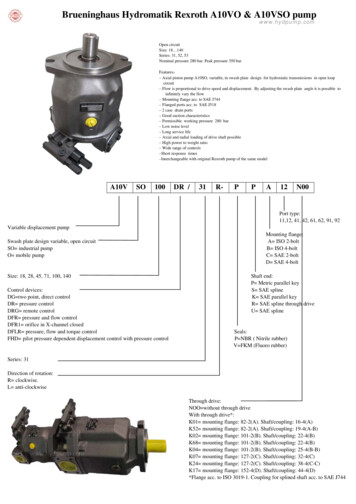
Axial Piston Variable PumpA10VSORE 92711/01.121/48Replaces: 06.09andRE 92707/11.10Data sheetSeries 31Sizes 18 to 140Nominal pressure 280 barMaximum pressure 350 barOpen circuitContentsFeaturesType code for standard program2Technical data4Technical data, standard unit6Technical data, high-speed version7–– Variable pump in axial piston swashplate design for hydro static drives in an open circuit–– The flow is proportional to the drive speed and the displace mentDG – Two-point control, directly operated10–– The flow can be steplessly varied by adjustment of theswashplate angle.DR – Pressure control11–– 2 case drain portsDRG – Pressure control, remotely operated12–– Excellent suction characteristicsDFR, DFR1 – Pressure and flow control13–– Low noise levelDFLR – Pressure, flow and power control14–– Long service lifeED – Electro-hydraulic pressure control15–– Axial and radial load capacity of drive shaftER – Electro-hydraulic pressure control16–– Favorable power/weight ratioDimensions sizes 18 to 14018–– Versatile controller rangeDimensions through drive36–– Short control timeSummary mounting options41Combination pumps A10VO A10VO42–– The through drive is suitable for adding gear pumps and axialpiston pumps up to the same size, i.e., 100% through drive.Connector for solenoids44Installation instructions46General instructions48
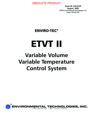
2/48Bosch Rexroth AGA10VSO Series 31 RE 92711/01.12Type code for standard d version (without symbol)01 HFA, HFB, HFC hydraulic fluid (except for Skydrol)High-speed version0910111213182845lll71 100 140lll–lllllE––llllHAxial piston unit02 Swashplate design, variable, nominal pressure 280 bar, maximum pressure 350 barA10VSOperation mode03 Pump, open circuitOSize (NG)04 Geometric displacement, see table of values on pages 6 and 718284571 100 140llllllDGllllllDRX-T openllllllDFRX-T Control deviceTwo-point control, directly operatedPressure controlwith flow control, hydraulicwith swivel angle control, electricpressure and swivel-angle control, electric05with pressure cut-off, remotely operatedhydraulicelectricalnegative characteristicpositive R712)24VllllllER722)–lllllDFLRPressure, flow and power controlSeries06 Series 3, Index 10731Direction of rotationViewed on drive shaftSeals08 FKM (fluor-caoutchouc)1)2)clockwiseRcounter clockwiseLVSee RE 30030The following must be taken into account during project planning:Excessive current levels (I 1200 mA with 12 V or I 600 mA with 24 V) to the ER solenoid can result in undesired increaseof pressure which can lead to pump or system damage:- Use Imax current limiter solenoids.- A sandwich plate pressure reducing valve can be used to protect the pump in the event of overflow.An accessory kit with pressure reducing sandwich plate can be ordered from Rexroth under part number R902490825. availablem on request– not available
RE 92711/01.12 A10VSO Series 31Bosch Rexroth AG3/48Type code for standard programA10VSO020301091011Drive shaftSplined shaftANSI B92.1aParallel keyed shaftDIN 6885Mounting flangeISO 3019-2/043105–0607091011121318284571 100 140standard shaftllllllSsimilar to shaft "S" however for higher input torquellll––RllllllPABnot for through drive1828452-holelll71 100 140–l l4-hole––––182845lll71 100 140–l l12–––l–4218l28l45l71 100 140l l lN009T 16/32DPllllK013/4 in11T 16/32DPllllllK527/8 in13T 16/32DP–lllllK681 in15T 16/32DPService line portSAE flange ports on opposite side, metric fastening threadThrough drivewithout through driveFlange ISO 3019-1diameter82-2 (A)5/8 in127-2 (C)–l–coupling for splined shaft1)Diameter101-2 (B)12V08ll––llllK041 1/4 in 14T 12/24DP–––lllK071 1/2 in 17T 12/24DP––––llK24152-4 (D)1 3/4 in 13T 8/16DP–––––lK17Ø 63, metric 4-holeshaft key Ø 25–lllllK57Flange ISO 3019-2Diameter80, 2-hole3/4 in11T 16/32DPllllllKB2100, 2-hole7/8 in13T 16/32DP–lllllKB31 in15T 16/32DP––llllKB4125, 2-hole1 1/4 in 14T 12/24DP–––lllKB51 1/2 in 17T 12/24DP––––llKB61 3/4 in 13T 8/16DP–––––lKB718l28l45l71 100 140l l l180, 4-holeConnectors for solenoids2)13 HIRSCHMANN connector – without suppressor diode1)2)Coupling for splined shaft as per ANSI B92.1aConnectors for other electric components can deviate. availablem on request– not availableH
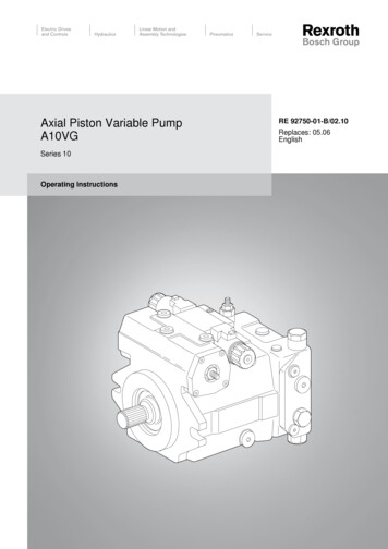
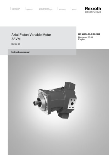
4/48Bosch Rexroth AGA10VSO Series 31 RE 92711/01.12Technical dataHydraulic fluidNotes on the choice of hydraulic fluidBefore starting project planning, please refer to our datasheets RE 90220 (mineral oil) and RE 90221 (environmentallyacceptable hydraulic fluids) for detailed information regardingthe choice of hydraulic fluid and application conditions.In order to select the correct hydraulic fluid, it is necessary toknow the operating temperature in the reservoir (open circuit)in relation to the ambient temperature.When using environmentally acceptable hydraulic fluids,the limitations regarding technical data and seals must beobserved. Please contact us. When ordering, indicate thehydraulic fluid that is to be used.Operating viscosity rangeFor optimum efficiency and service life we recommend that theoperating viscosity (at operating temperature) be selected inthe rangenopt opt. operating viscosity 16 . 36 mm /s2referred to reservoir temperature (open circuit).Limits of viscosity rangeFor critical operating conditions the following values apply:10 mm2/sshort-term (t 1 min)at max perm. case drain temperature of 90 C.nmin The hydraulic fluid should be selected so that within the operat ing temperature range, the viscosity lies within the optimumrange (nopt), see shaded section of the selection diagram. Werecommend to select the higher viscosity grade in each case.Example: at an ambient temperature of X C the operatingtemperature is 60 C. In the optimum operating viscosity range(nopt; shaded area) this corresponds to viscosity grades VG 46resp. VG 68; VG 68 should be selected.Important:The case drain temperature is influenced by pressure and inputspeed and is always higher than the reservoir temperature.However, at no point in the component may the temperatureexceed 90 C. The temperature difference specified on the leftis to be taken into account when determining the viscosity inthe bearing.If the above conditions cannot be met, due to extreme operat ing parameters please contact us.Please also ensure that the max. case drain temperature of90 C is not exceeded in localized areas (for instance, in thebearing area).The fluid temperature in the bearing area isapprox. 5 K higher than the average case drain temperature.Filtration of the hydraulic fluidThe finer the filtration the better the cleanliness level of thehydraulic fluid and the longer the service life of the axial pistonunit.Depending on the installation situation, special measuresare necessary at temperatures between -40 C and -25 C.Please contact us.In order to guarantee the functional reliability of the axial pistonunit it is necessary to carry out a gravimetric evaluation of thehydraulic fluid to determine the particle contamination and thecleanliness level according to ISO 4406. A cleanliness level ofat least 20/18/15 must be maintained.At very high hydraulic fluid temperatures (90 C to maximum115 C), a cleanliness level of at least 19/17/14 according toISO 4406 is necessary.For detailed information on operation with low temperaturessee data sheet RE 90300-03-B.If the above cleanliness levels cannot be maintained, pleasecontact us.nmax 1000 mm2/sshort-term (t 1 min)on cold start(p 30 bar, n 1000 rpm, tmin -25 C)Selection y n [mm2/s]20010VG 68VG 46VG 32VG 222000100604036nopt.2016105-40-25tmin -40 C-10 0 103050Temperature t in C70Fluid temperature range905115tmax 115 C
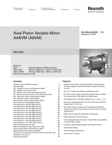
RE 92711/01.12 A10VSO Series 31Bosch Rexroth AG5/48Technical dataOperating pressure rangePressure at service line port BDefinitionNominal pressure pnom 280 bar absoluteNominal pressure pnomThe nominal pressure corresponds to the maximum designpressure.Maximum pressure pmax 350 bar absoluteSingle operating period 2.5 msTotal operating period 300 hMinimum pressure (high-pressure side) 10 barabsolute1)Pressure pRate of pressure change RA max 16000 bar/spnomMaximum pressure pmaxThe maximum pressure corresponds to the maximum operat ing pressure within the single operating period. The total of thesingle operating periods must not exceed the total operatingperiod.Minimum pressure (high-pressure side)Minimum pressure in the high-pressure side (port B) that isrequired in order to prevent damage to the axial piston unit.The minimum pressure depends on the speed and displace ment of the axial piston unit.DtDpRate of pressure change RAMaximum permissible pressure build-up and pressure reduc tion speed with a pressure change over the entire pressurerange.Pressure at suction port S (inlet)Minimum pressure pS min 0.8 bar absoluteMaximum pressure pS max 10 bar1) absoluteNotePlease contact us for values for other hydraulic fluids.Pressure pTime tSingle operating periodt1t2tnMaximum pressure pmaxNominal pressure pnomCase drain pressureMaximum permissible case drain pressure (at port L, L1):Maximum 0.5 bar higher than the inlet pressure at port S,however not higher than 2 bar absolute.Minimum pressure (high-pressure side)pL max abs 2 bar absolute1)1)Other values on requestTime tTotal operating period t1 t2 . tn
6/48Bosch Rexroth AGA10VSO Series 31 RE 92711/01.12Technical data, standard unitTable of values (theoretical values, without efficiencies and tolerances: values rounded)SizeNG18284571100140Geometrical displacement per revolutionVg maxcm318284571100140maximum at Vg maxnnomrpm330030002600220020001800maximum at Vg Vg maxnmax perm rpm390036003100260024002100at nnom and Vg maxqv maxl/min5984117156200252at nE 1500 rpm and Vg maxqvE maxl/min274268107150210at nnom, Vg maxPmaxkW3039557393118at nE 1500 rpm and Vg maxPE maxkW12.62032507098 p 280 barTmaxNm80125200316445623 p 100 )FlowPower at Dp 280 barTorqueat Vg max andRotary stiffness,drive shaftMoment of inertial rotary groupAngular acceleration,maximum2)Filling capacityWeight (without through drive) approx. mThe values are applicable:- for an absolute pressure pabs 1 bar at suction port S- within the optimum viscosity range from nopt 16 to 36 mm2/s- for mineral-oil based hydraulic fluid.1)2)The scope of application lies between the minimum necessary and the maximum permissible drive speeds.Valid for external excitation (e.g. diesel engine 2- to 8-fold rotary frequency, cardan shaft 2-fold rotary frequency).The limiting value is only valid for a single pump.The loading capacity of the connecting parts must be taken into account.NoteExceeding the maximum or falling below the minimum permissible values can lead to a loss of function, a reduction in operationalservice life or total destruction of the axial piston unit. We recommend to check the loading through tests or calculation / simula tion and comparison with the permissible values.Determination of sizeFlowqV TorqueT PowerP Vg n hV[l/min]1000Vg Dp[Nm]20 p hmh2p T n60000 qV Dp600 ht[kW]Vg Displacement per revolution in cm3Dp Differential pressure in barn Speed in rpmhV Volumetric efficiencyhmh Mechanical-hydraulic efficiencyht Total efficiency(ht hV hmh)
RE 92711/01.12 A10VSO Series 31Bosch Rexroth AG7/48Technical data, high-speed versionTable of values (theoretical values, without efficiencies and tolerances: values rounded)SizeNG4571100140Geometrical displacement per revolutionVg maxcm34571100140maximum at Vg maxnnomrpm3000255023002050maximum at Vg Vg maxnmax perm rpm3300280025002200qv maxl/min135178230287PmaxkW6383107134 p 280 barTmaxNm200316445623 p 100 m/rad4102576545––Speed1)Flowat nnom and Vg maxPower at Dp 280 barat nnom, Vg maxTorqueat Vg max andRotary stiffness,drive shaftcNm/rad4123280627132335188406Moment of inertial rotary groupJTWkgm20.00330.00830.01670.0242Angular acceleration, maximum2)arad/s24000330027002700Filling capacityVL1.01.62.23.0kg21334560PWeight (without through drive) approx. mThe values are applicable:- for an absolute pressure pabs 1 bar at suction port S- within the optimum viscosity range from nopt 16 to 36 mm2/s- for mineral-oil based hydraulic fluid.1)2)The scope of application lies between the minimum necessary and the maximum permissible drive speeds.Valid for external excitation (e.g. diesel engine 2- to 8-fold rotary frequency, cardan shaft 2-fold rotary frequency).The limiting value is only valid for a single pump.The loading capacity of the connecting parts must be taken into account.NoteExceeding the maximum or falling below the minimum permissible values can lead to a loss of function, a reduction in operationalservice life or total destruction of the axial piston unit. We recommend to check the loading through tests or calculation / simula tion and comparison with the permissible values.Sizes 45, 71, 100 and 140 are optionally available in high-speed version.External dimensions are not affected by this option.
8/48Bosch Rexroth AGA10VSO Series 31 RE 92711/01.12Technical dataPermissible radial and axial loading on the drive shaftSizeNGRadial force maximumat a/218284571100140N35012001500190023002800 Fax max N70010001500240040004800FqFq maxa/2 a/2aAxial force maximum FaxPermissible input and through-drive torquesSizeNG18284571100140Torqueat Vg max and Dp 280 bar1)TmaxNm8012520031
125, 2 hole 1 1/4 in 14T 12/24DP – – – l l l KB5 1 1/2 in 17T 12/24DP – – – – l l KB6 180, 4 hole 1 3/4 in 13T 8/16DP – – – – – l KB7 Connectors for solenoids2) 18 28 45 71 100 140 13 HIRSCHMANN connector – without suppressor diode l l l l l l H 1) Coupling for splined shaft as per ANSI B92.1a