Transcription
OBSOLETE PRODUCTStock ID: CAT-ETVTAugust, 2002 2002 Environmental Technologies, Inc.Largo, Florida USAENVIRO-TEC ETVT IIVariable VolumeVariable TemperatureControl System
OBSOLETE PRODUCTTABLEOFCONTENTSETVT-II SYSTEM OVERVIEW . . . . . . . . . . . . . . . . . . . . . . . . . . . . . . . . . . . . . . . . . 4SYSTEM CONTROL UNIT . . . . . . . . . . . . . . . . . . . . . . . . . . . . . . . . . . . . . . . . . . . 6ZONE CONTROLLERS . . . . . . . . . . . . . . . . . . . . . . . . . . . . . . . . . . . . . . . . . . . . . . 8BYPASS CONTROLLER . . . . . . . . . . . . . . . . . . . . . . . . . . . . . . . . . . . . . . . . . . . . . 11SDR TERMINAL UNIT SPECIFICATIONS . . . . . . . . . . . . . . . . . . . . . . . . . . . . . . . . 12SGX TERMINAL UNIT SPECIFICATIONS . . . . . . . . . . . . . . . . . . . . . . . . . . . . . . . . 14WDDCMON MONITOR/SETUP SOFTWARE. . . . . . . . . . . . . . . . . . . . . . . . . . . . . . 16SYSTEM DESIGN GUIDELINES . . . . . . . . . . . . . . . . . . . . . . . . . . . . . . . . . . . . . . . 21SAMPLE APPLICATION . . . . . . . . . . . . . . . . . . . . . . . . . . . . . . . . . . . . . . . . . . . . 24ETVT-II SYSTEM GUIDE SPECIFICATIONS . . . . . . . . . . . . . . . . . . . . . . . . . . . . . . . 262ETVT-II Catalog August, 2002 Environmental Technologies, Inc.
OBSOLETE PRODUCTETVT-II SYSTEM August, 2002 Environmental Technologies, Inc. ETVT-II Catalog3
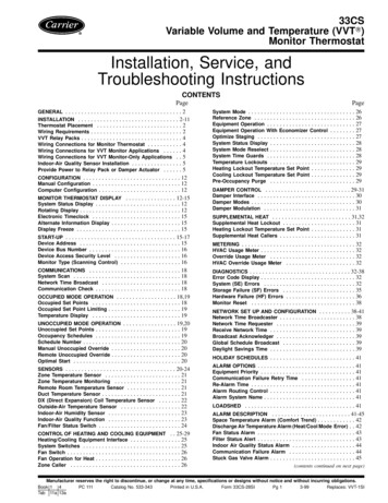
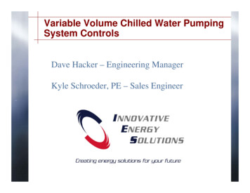
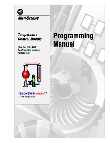
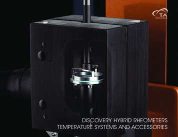
OBSOLETE PRODUCTETVT-II SYSTEM OVERVIEWDirect Digital Zone ControlThe Environmental Technologies Variable Temperature(ETVT-II) control system provides Direct Digital Control(DDC) of multi-zone heating and cooling systems. TheETVT-II system components are designed to provide theadvantages of intelligent, microprocessor-based comfortcontrol at a very reasonable cost.Small or Large Building UseA typical ETVT-II installation consists of a System ControlUnit (SCU), 1 to 64 VAV terminals, a pressure relief(bypass) terminal unit, and a static pressure (bypass) terminal controller. However, up to 99 SCU's can be linkedtogether for larger projects and monitored from a centralpersonal computer (PC).The use of DDC controllers allows the entire system tocommunicate essential information between the controllersso that the system is able to make the most efficient useof the HVAC unit's heating and cooling capacity to achieveoptimum temperature control.Direct Expansion or Hydronic SystemsThe ETVT-II system is frequently applied with directexpansion rooftop and split systems which require maintaining a constant DX coil airflow. The ETVT-II pressurerelief (bypass) system maintains supply duct static pressure and coil CFM. This system consists of a standalonebypass terminal controller and one or more bypass terminal units.The ETVT-II system allows the building manager to easily monitor the entire system and, if desired, modify itsoperation as building usage or requirements change.Pressure Independent ControlThe ETVT-II zone terminal controllers feature pressureindependent operation, automatic changeover, and propertional, integral, and derivative (PID) temperature control.Fan Powered TerminalsIn addition to standare single duct terminal units, the ETVTII system is suitable for use with Enviro-Tec's entire lineof fan powered, hydronic heat, and electric reheat terminal units. This provides a degree of flexibility that waspreviously only possible with expensive high-end DDC systems.Commercial/Industrial Duty EquipmentEven though the ETVT-II system is designed to be costeffective in low tonnage installations, it uses Enviro-Tec'shigh quality commercial grade pressure independent DDCcontrollers and terminal units for unsurpassed functionality and reliability.All ETVT-II controllers, terminal units, and computer programs are designed and manufactured by Enviro-Tec.This sole sourcing yields reliable, consistent operation andprovides fast solutions to potential HVAC system designproblems.4Central HVAC Unit ControlThe System Control Unit (SCU) provides the HVAC unitcontrol portion of the system. It communicates with allof the zone terminal controllers in the system to determinethe building heating and/or cooling requirements. Basedon these requirements and its discharge temperature sensor, the SCU controls the HVAC unit by activating anddeactivating relays which control the HVAC unit fan withup to seven stages of heating and/or cooling.Output relays are field definable, providing maximum flexibility and backup output devices for smaller systems.Operator InterfaceThe System Control Unit (SCU) includes a Liquid CrystalDisplay / Keypad operator's panel which can be used toconfigure and monitor all zone controllers in the system.The communications interface socket allows a Windows compatible computer to be connected to the system usinga factory supplied cable. A powerful, user friendlycomputer program allows configuration and monitoring ofthe SCU and all of the zone controllers in the systemdirectly or remotely via an optional 2400 baud modem.ETVT-II Catalog August, 2002 Environmental Technologies, Inc.
OBSOLETE PRODUCTETVT-II SYSTEM DIAGRAM August, 2002 Environmental Technologies, Inc. ETVT-II Catalog5
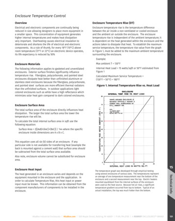
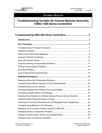
OBSOLETE PRODUCTSYSTEM CONTROL UNIT (SCU)The System Control Unit (SCU) monitors each zonetemperature. Its control logic determines the central air conditioning unit mode status, either heating, cooling, or ventilation.The SCU’s battery-backed real time clock / calendar withautomatic leap-year and daylight savings time adjustments schedules occupied (daytime) and unoccupied (nightsetback or setup) periods for each day of the week and aspecial holiday schedule.An electronic duct temperaturesensor measures the discharge air temperature from the HVAC unit. TheSCU meets zone load demands whileavoiding low suction temperaturesand coil frosting while in the coolingmodes with built in off-cycle timers.The SCU protects a heat pump froma manual reset nuisance tripout on highpressure by sensing a high supply airtemperature condition and cycling offmechanical heating for a preset offcycle period.Configuration and monitoring of all ofthe controllers in the system is doneat the SCU. Up to 99 System ControlUnits can be connected together ontheir own communications network. With 64 terminals perSCU, one ETVT-II system could serve an installation withover 6,000 terminal units and 99 central air handling units.A Windows compatible PC on-site or connected bymodem allows an owner operator, system designer, installer,or service technician to set up all air terminals and systemoperating parameters including zone temperature setpointsand to perform system check-out and diagnostics.Sequence of OperationsThe System Control Unit provides eight field definable output control relays to interface with the HVAC unit. Bysequencing these relays, the SCU will call for fan operation, up to 7 stages of heating, or up to 7 stages ofcooling, heat pump changeover, or any combination of 8outputs.6Once every minute, the SCU communicates with each ofthe zone controllers connected on its communicationsnetwork to determine the total heating and/or coolingrequirements of the building. A zone vote weightingsystem determines optimum central heating or cooling operation.Configuration settings in the SCU control the minimumand maximum duration of the cycles to limit excessivecycling of the HVAC unit. A preset ventilation periodbetween heating and cooling changeover allows theductwork to be purged saving energyand protecting the HVAC unit.The SCU determines the requiredmode of operation. It turns individualheating or cooling stages on or off tomaintain the appropriate discharge airtemperature. The turn-on and turn-offtemperatures for each individual stageof heating or cooling can be configuredseparately. A programmable anticyclefunction for each output ensures thatthe cooling compressor(s) will not beshort-cycled during normal operationor after a power failure.The SCU schedules up to fourteenprogrammable occupied periods perweek (two per day) and 16 programmable holiday periods. When the system is in unoccupiedmode, a command is sent to all the VAV units on the network to revert to their unoccupied mode settings. If the SCUis in unoccupied mode and all units are within theprogrammed temperature limits, the HVAC unit will be shutdown.In the occupied mode, when all zones are satisfied, the unitfan operates continuously to maintain ventilation and airmotion. All terminal units are set at minimum CFMoperation. The nominal air motion creates greater comfortand improves dilution of stale air with outside air from thecentral HVAC unit.ETVT-II Catalog August, 2002 Environmental Technologies, Inc.
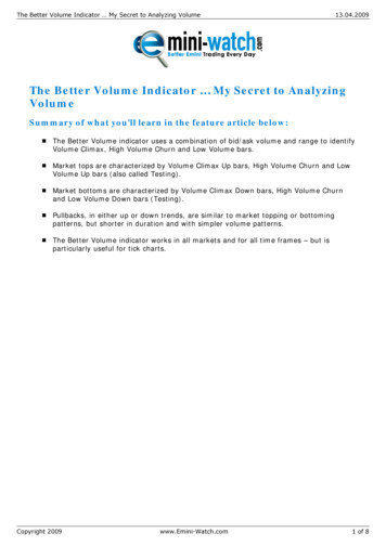
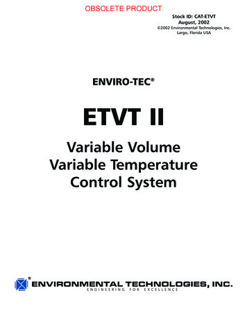
OBSOLETE PRODUCTSCU FEATURESComponent DesignationsSCU-LT8: The System Control Unit features: Two line by 16 character liquid crystaland 20-key operator's panelCommunications interface cableMonitor/access softwareTransformerDisconnectLine block Heating and cooling manual override switchesTerminal strip for connection to AHUPainted enclosure with hinged access doorEight field definable relays for control of anycombination of fan, heating, cooling andchangeover outputsSystem Control UnitDimensional Data August, 2002 Environmental Technologies, Inc. ETVT-II Catalog7
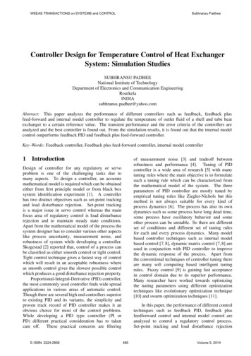
OBSOLETE PRODUCTZONE CONTROLLERSThe DDC zone controller is microprocessor based andintelligently performs proportional, integral, and derivative(PID) control of the terminal functions including heatingor cooling votes, damper operation, and optional fanand/or electric heat to provide optimum zone comfort.The zone controller provides pressure independent VAVflow control and automatic changeover operation. Eachzone terminal unit includes a regular thermostat or aSmart-Stat display thermostat. Both thermostats includea zone temperature sensor, communications interfaceconnector, and an unoccupied mode override switch.The standard thermostat includes a temperature setpointcontrol knob. The Smart-Stat includes a 4-digit greenLED display, a 6-position keypad, and a locking cover. TheSmart-Stat lets the occupant see: Cooling setpoint Heating setpoint Duct temperature Room temperature Unit CFMPressure Independent OperationEach zone terminal controller contains Enviro-Tec'sexclusive flow compensated differential pressuretransducer. In a VAV system, the static pressure in the ductwill change whenever any zone controller opens orcloses its damper. This flow transducer enables the zonecontroller to calculate how much air is being supplied tothe zone so that it can keep the airflow constant even whenthe static pressure in the duct is changing. This is calledpressure independent operation. Pressure independentmeans that each zone is not affected by every other zonein the system and prevents constant temperature swings andnoisy breathing of the system. In addition, the zonecontroller can accurately maintain minimum ventilationairflow levels to ensure adequate ventilation whilemaximizing energy efficiency.8Stand-Alone OperationAlthough much of the power of the ETVT-II system liesin the ability of the controllers to communicate theirheating and cooling needs to the System Control Unit, thezone controllers are designed to provide stand-aloneoperation if required. Because of this capability, if one partof the system loses power or malfunctions, the rest of thesystem can still operate normally. Each zone controllerkeeps track of the last time it communicated with the SCU;if a controller hasn’t communicated within the previous 90seconds, it will automatically switch to its occupied(daytime) operation and continue to operate normally. Thezone controllers do not rely on the SCU to tell them whetherthe HVAC unit is currently supplying hot air or cold airsince each controller has its own electronic ducttemperature sensor. This sensor allows the controller todetermine the temperature of the supply air, compare thattemperature with the zone temperature, and then decidewhether to use the supply air for heating or cooling.PID Temperature ControlIn order to provide optimum temperature control, the zonecontrollers use a proportional, integral, and derivative (PID)control algorithm.This means that the controller has the ability to intelligently determine the exact amount of cooling or heatingrequired by the zone.PID control is a common-sense approach to temperaturecontrol. The proportional factor means that more heatingor cooling is supplied as the zone temperature gets furtheraway from set-point. The integral factor adds time intothe equation, which means that if a zone has been too hotor too cold for a period of time, the heating or cooling isincreased or decreased until the proper level is achieved.The derivative factor means that the zone controller willcompensate for rapid temperature changes, such as a largegroup of people entering a previously unoccupied conference room.ETVT-II Catalog August, 2002 Environmental Technologies, Inc.
OBSOLETE PRODUCTZONE CONTROLLERSConfiguration SettingsEach zone terminal controller has flexibility in terms ofapplication and operation. The configuration settings aremodified using the WDDCMON Monitor/Setup Software(see page 16) and are retained by the controllersnon-volatile memory in the event of a power failure.The zone terminal controller has programmable setpointsfor occupied and unoccupied control modes includingheating and cooling maximum and minimum airflow.Vote weighting factors for heating and cooling permitcertain controllers to be given a higher or lower prioritythan others in determining the operation of the HVAC unit.An override time setting is also provided which allows acontroller to request activation of the HVAC unit if theswitch at the controller’s thermostat is depressed. Actualoverride time is totaled and stored in each zone.Smart-Stat Units with reheat capability, including fan inductionterminals, can be configured to operate independently basedon local demands for heat without requiring the HVAC uni
The System Control Unit (SCU) provides the HVAC unit control portion of the system. It communicates with all of the zone terminal controllers in the system to determine the building heating and/or cooling requirements. Based on these requirements and its discharge temperature sen-sor, the SCU controls the HVAC unit by activating and deactivating relays which control the HVAC unit fan with up .