Transcription
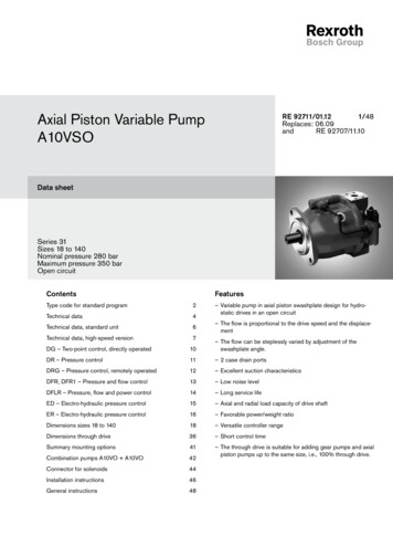
Electric Drivesand ControlsHydraulicsLinear Motion andAssembly TechnologiesPneumaticsAxial Piston Variable Double PumpA20VG/A22VGServiceRA 93220-A/10.10Replaces: 05.091/28Data sheetSeries 11Sizes 45A20VG Nominal pressure 4350 psi (300 bar)Maximum pressure 5100 psi (350 bar)A22VG Nominal pressure 5100 psi (350 bar)Maximum pressure 6100 psi (420 bar)Closed circuitFeaturesContentsOrdering code for standard program2Technical data4HW – Proportional control hydraulic, mechanical servo9– Variable double pump with two axial piston rotary groupswith swashplate design for hydrostatic drives in closedcircuitEP – Proportional control electric11– The flow is proportional to the drive speed and displacement.HT – Hydraulic control, direct controlled13ET – Electric control, direct controlled14– The flow increases as the angle of the swashplate isadjusted from zero to its maximum value.DA control valve, fixed setting15Dimensions size 4516Through drive dimensions20– Only one shared port for case drain fluid for both circuitsOverview of attachments21Combination pumps22– Service line ports alternatively left or right (viewed fromdrive shaft)Boost pump22High-pressure relief valves22Mechanical stroke limiter23Ports X3 and X4 for stroking chamber pressure23Sensors24Installation situation for coupling assembly25Connector for solenoids25Installation instructions26General instructions28– Flow direction changes smoothly when the swashplate ismoved through the neutral position.– Compact design for tight installation conditionsNoteOnly for series no smaller than 200 units per year.Please consult us regarding smaller series.
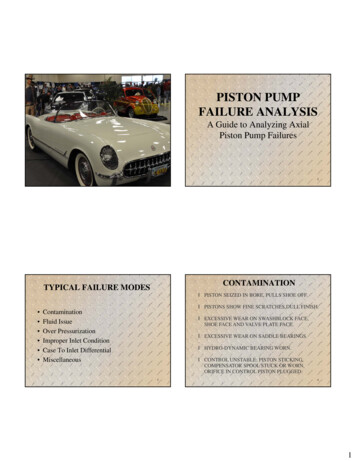
2/28Bosch Rexroth Corp.A20VG/A22VG Series 11RA 93220-A/10.10Ordering code for standard programG 04501010203/ 11 A040506Axial piston unitSwashplate design, variable0708091011N B2121314A151617181920Nominal pressure 4350 psi (300 bar), maximum pressure 5100 psi (350 bar)A20VNominal pressure 5100 psi (350 bar), maximum pressure 6100 psi (420 bar )A22VOperation mode02 Double pump, closed circuit03GSize (NG)Theoretical displacement see table of values on page 7in cm3045in in3/rev2.81Control deviceProportional control hydraulicmechanical servo, hexagon shaftwithout neutral position switch HW1with neutral position switch HW7Proportional control electricU 12 V DC EP1 EP2 HT1U 12 V DC ET1U 24 V DC ET2U 24 V DC04Hydraulic control, direct controlledElectric control, direct controlled,two pressure reduction valves (DRE) per circuit0506Connector for solenoids1)Without0DEUTSCH - molded connector, 2-pin – without suppressor diodePSwivel angle indicatorWithout0Electric swivel angle sensor2)RAuxiliary function 1 (pilot pressure port)With ports X1 and X2107 With ports X3 and X43With ports X1, X2 and X3, X44Auxiliary function 2 (mechanical stroke limiter)Without008 With mechanical stroke limiter on one side,externally variable, on the same side as the service line portsEWith mechanical stroke limiter on both sides, externally variable09DA control valveWithoutWith DA control valve fixed settingMHWHTEPET 0 –1Series10 Series 1, Index 111Version of port and fixing threads11 ANSIA Available On request– Not available1) Connectors for other electric components can deviate.2) See page 24
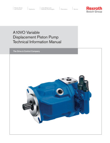
RA 93220-A/10.10Bosch Rexroth Corp.A20VG/A22VG Series 113/28Ordering code for standard programG 04501120203/ 11 A04050607080910Direction of rotationViewed from drive shaft11N eals13 NBR (nitrile-caoutchouc), shaft seal ring in FKM (fluor-caoutchouc)Mounting flange14 SAE J744151617N101-2 (B)Drive shaftSplined shaft ANSI B92.1a-1976B215T 16/32DP S51 1/4 in 14T 12/24DP S71 inService line portsSAE threaded ports A and B, left (viewed from drive shaft)3SAE threaded ports A and B, right (viewed from drive shaft)4Boost pumpWithout boost pump (standard)3)UWith boostpump3)FThrough driveFlange SAE J744Coupling for splined shaft4)Mounting variantSymbol5) Designation DiameterDiameterDesignation 18 WithoutA25/8 in 9T 16/32DPS2 A2S2101-2 (B)B27/8 in 13T 16/32DPS4 B2S41 inS5 B2S5High-pressure valvesWith high-pressure relief valve,19 direct controlledwithout bypass15T 16/32DPSetting range3600 to 4650 psi (250 to 320 bar) (A20VG)3600 to 5650 psi (250 to 390 bar) (A22VG)Standard / special versionStandard version20combined with attachment part or attachment pumpSpecial version4)5)-K-SNoteThis unit is only available “without pressure cut-off”.Short designation X on a feature refers to a special version not covered by the ordering code. AvailableA-0combined with attachment part or attachment pump3)000082-2 (A) On request– Not availableFor pressure filtration, the feed is performed via port G.Pressure or suction filtration to be provided by the customer.Coupling for splined shaft acc. ANSI B92.1a-1976Order of fixing bores viewed from through drive-T
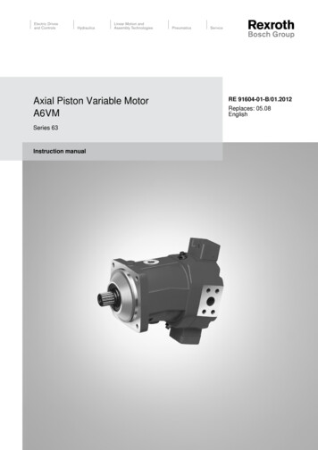
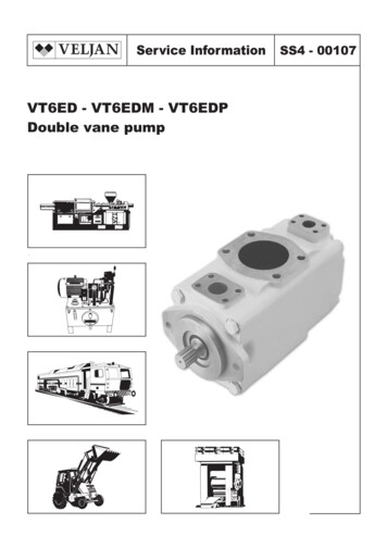
4/28Bosch Rexroth Corp.A20VG/A22VG Series 11RA 93220-A/10.10Technical dataHydraulic fluidDetails regarding the choice of hydraulic fluidBefore starting project planning, please refer to our datasheets RE 90220 (mineral oil) and RE 90221 (environmentallyacceptable hydraulic fluids) for detailed information regardingthe choice of hydraulic fluid and application conditions.The correct choice of hydraulic fluid requires knowledge of theoperating temperature in relation to the ambient temperature:in a closed circuit the circuit temperature.The A20VG/A22VG variable pump is not suitable for operationwith HFA, HFB and HFC hydraulic fluid. If HFD or environmentally acceptable hydraulic fluids are being used, the limitationsregarding technical data and seals must be observed.Please contact us.When ordering, indicate the hydraulic fluid that is to be used.Selection (0 )(20 )(40 )(60 ) (80 ) (100 )7400(1600)170 (36)νopt1000(-20 )010VG 68VG 46VG 32VG 22VGViscosity ν [SUS (mm2/s)](-40 )7000 (1600)5000 (1000)3000 (600)2000 (400)80 (16)(10)The hydraulic fluid should be chosen so that the operating viscosity in the operating temperature range is within the optimumrange (νopt), see shaded area of the selection diagram. Werecommended that the higher viscosity class be selected ineach case.Example: At an ambient temperature of X F (X C), an operating temperature of 140 F (60 C) is set in the circuit. In theoptimum operating viscosity range (νopt. shaded area), thiscorresponds to the viscosity classes VG 46 or VG 68; to beselected: VG 68.NoteThe case drain temperature, which is affected by pressure andspeed, is always higher than the circuit temperature. At nopoint of the component may the temperature be higher than240 F (115 C), however. The temperature difference specifiedbelow is to be taken into account when determining the viscosity in the bearing.If the above conditions cannot be maintained due to extremeoperating parameters, please contact us.5040(5)(-40 ) (-25 ) (-10 ) (0 ) (10 )-40 -13 0 (30 )20 40 60 80 (50 )(70 ) (90 )42 (5)(115 )120 160 195 240 tmin -40 F Fluid temperature range t in [ F ( C)](-40 C)tmax 240 F( 115 C)Viscosity and temperatureViscosity[SUS (mm2/s)]Transport and storage(Cold) start-up1)νmax 7400(1600)Permissibletemperature differenceWarm-up phaseν 7400 to 1850(1600 to 400)Operating phaseTemperature differenceMaximum temperatureContinuous operationShort-term operationShaft seal ring FKM1)1)ν 1850 to 60(400 to 10)νopt 80 to 170(16 to 36)νmin 60 to 42(10 to 5)TemperatureCommentTmin -58 F (-50 C)Topt 41 F to 68 F( 5 C to 20 C)TSt -40 F(-40 C)up to 12 months with standard factory preservationup to 24 months with long-term factory preservationΔT 45 F(25 C)between axial piston unit and hydraulic fluidT -40 F to -13 F(-40 C to -25 C)at pnom, 0.5 nnom and t 15 minΔT approx. 9 F(5 C)240 F (115 C)between hydraulic fluid in the bearing and the casedrain fluids at port T.in bearing230 F (110 C)measured at port Tmeasured at port T,no restriction within the permissible dataT -13 F to 195 F(-25 C to 90 C)Tmax 230 F( 110 C)T 240 F ( 115 C)t 3 min, without load (p 725 psi (50 bar)),n 1000 rpmmeasured at port T, t 3 min, p 0.3 pnomsee page 5At temperatures below -13 F (-25 C), an NBR shaft seal ring is required(permissible temperature range: -40 F to 195 F (-40 C to 90 C)).
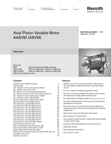
RA 93220-A/10.10Bosch Rexroth Corp.A20VG/A22VG Series 115/28Technical dataFiltration of the hydraulic fluidShaft seal ringFiltration improves the cleanliness level of the hydraulic fluid,which, in turn, increases the service life of the axial piston unit.Permissible pressure loadingDepending on the system and the application, for the A20VGand A22VG, we recommendFilter cartridges β20 100.With an increasing differential pressure at the filter cartridges,the β-value must not deteriorate.At very high hydraulic fluid temperatures 195 F to maximum240 F (90 C to maximum 115 C), a cleanliness level of atleast 19/17/14 according to ISO 4406 is necessary.If the above classes cannot be achieved, please contact us.The service life of the shaft seal ring is affected by the speedof the pump and the case drain pressure. It is recommendedthat the average, continuous case drain pressure 45 psi(3 bar) absolute at operating temperature not be exceeded(maximum permissible case drain pressure 90 psi (6 bar) absolute at reduced speed, see diagram). Short-term (t 0.1 s)pressure spikes of up to 145 psi (10 bar) absolute arepermitted. The service life of the shaft seal ring decreases withan increase in the frequency of pressure spikes.The case pressure must be equal to or greater than theexternal pressure on the shaft seal ring.90 (6)75 (5)Perm. pressure pabs max [psi (bar)]To ensure the functional reliability of the axial piston unit, agravimetric evaluation is necessary for the hydraulic fluid todetermine the amount of contamination by solid matter andto determine the cleanliness level according to ISO 4406. Acleanliness level of at least 20/18/15 is to be maintained.60 (4)NG4545 (3)30 (2)15 (1)1000200030004000Speed n [rpm]Temperature rangeThe FKM shaft seal ring may be used for case drain temperatures from -13 F to 240 F (-25 C to 115 C).NoteFor application cases below -13 F (-25 C), an NBR shaftseal ring is necessary (permissible temperature range:-40 F to 195 F (-40 C to 90 C)).State NBR shaft seal ring in plain text when ordering.Please contact us.
6/28Bosch Rexroth Corp.A20VG/A22VG Series 11RA 93220-A/10.10Technical dataOperating pressure rangeDefinitionVariable double pump A20VGNominal pressure pnomThe nominal pressure corresponds to the maximum designpressure.Nominal pressure pnom 4350 psi (300 bar) absoluteMaximum pressure pmax 5100 psi (350 bar) absoluteSingle operating period 10 sTotal operating period 300 hVariable double pump A22VGPressure at service line port A or BNominal pressure pnom 5100 psi (350 bar) absoluteMaximum pressure pmax 6100 psi (420 bar) absoluteSingle operating period 10 sTotal operating period 300 hVariable double pump A20VG and A22VGMinimum pressure (high-pressure side) 365 psi (25 bar)Minimum pressure (inlet) 145 psi (10 bar)(boost pressure setting must be higher depending on system)Pressure pRate of pressure change RA max 130000 psi/s (9000 bar/s)pnomΔtMaximum pressure pmaxThe maximum pressure corresponds to the maximum operatingpressure within the single operating period. The sum ofthe single operating period must not exceed the totaloperating period.Minimum pressure (high-pressure side)Minimum pressure on the high-pressure side (A or B) that isrequired in order to prevent damage to the axial piston unit.Minimum pressure (inlet)Minimum pressure in inlet (A or B) that is required in order toprevent damage to the axial piston unit.Rate of pressure change RAMaximum permissible rate of pressure build-up and pressurereduction during a pressure change over the entire pressurerange.Pressure pPressure at service line port A or BSingle operating periodt1t2tnMaximum pressure pmaxNominal pressure pnomΔpMinimum pressure (high-pressure side)Time tBoost pumpPressure at suction port SDuration pS min (ν 140 SUS) 12 psi absolute((ν 30 mm2/s) 0.8 bar absolute)at cold starts, short-term (t 3 min) 7.5 psi (0.5 bar) absoluteMaximum pS max 75 psi (5 bar) absoluteNominal pressure pSp nom 365 psi (25 bar)Maximum pressure pSp max 580 psi (40 bar)Control pressureTo ensure the function of the control, the following controlpressure is required depending on the speed and operatingpressure:For controls EP and HWMinimum control pressurepSt min (at n 2000 rpm) 260 psi (18 bar)For controls ET and HTMinimum control pressurepSt min (at n 2000 rpm) 365 psi (25 bar)Time tTotal operating period t1 t2 . tn
RA 93220-A/10.10Bosch Rexroth Corp.A20VG/A22VG Series 117/28Technical dataTable of values (theoretical values, without efficiency and tolerances; values rounded)SizeDisplacementgeometrical, per revolutionNGvariable pump (for each rotary group)boost pump (at p 290 psi (20 bar))SpeedFlowPower3)Vg Sp45in32.81cm346in30.91cm314.9rpm3300at Vg maxnnomlimited maximum1)nmax limitedrpm3550intermittent maximum2)nmax interm.rpm3800minimumnminrpm500at nnom and Vg maxqv maxgpm2 x 40l/min2 x 152at nnom, Vg max andfor A20VGfor A22VGTorque3)Vg maxΔp 4350 psiPmaxhp204Δp 300 barPmaxkW152Δp 5100 psiPmaxhp239Δp 350 barPmaxkW177at Vg max andfor A20VGfor A22VGΔp 4350 psiTmaxlb-ft324Δp 300 barTmaxNm439Δp 5100 psiTmaxlb-ft380Δp 350 barTmaxNm512Δp 1450 psiTlb-ft108Δp 100 barTNm146Rotary stiffnessdrive shaft S7clb-ft/rad54435Nm/rad73804Moment of inertiarotary group 1J 3293rotary group 2J GR
4/28 Bosch Rexroth Corp. A20VG/A22VG Series 11 RA 93220-A/10.10. Technical data Filtration of the hydraulic fluid Filtration improves the cleanliness level of the hydraulic fluid, which, in turn, increases the service life of the axial piston unit. To ensure the functional reliability of the axial piston unit, a gravimetric evaluation is necessary for the hydraulic fluid to determine the .