Transcription
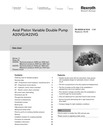
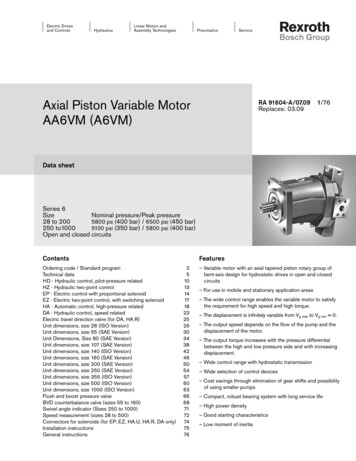
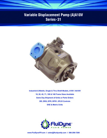
Electric Drivesand ControlsHydraulicsLinear Motion andAssembly TechnologiesPneumaticsAxial Piston Variable PumpAA10VGServiceRA 92750-A/06.09 1/44Replaces: 03.09Data sheetSeries 10Size 18 . 63Nominal pressure 4350 psi (300 bar)Peak pressure 5100 psi (350 bar)Closed circuitFeaturesContentsOrdering Code / Standard ProgramTechnical DataHigh-Pressure Relief ValvesPressure Cut-Off, DDG - Hydraulic Control, Direct OperatedMD - Mechanical Pivot Control (Size 18 only)HD - Hydraulic Control, Pilot-Pressure RelatedHW - Hydraulic Control, Mechanical ServoDA - Hydraulic Control, Speed RelatedEP - Electric Control, With Proportional SolenoidEZ - Elec. Two-Point Control, With Switching SolenoidUnit Dimensions, Size 18Unit Dimensions, Size 28Unit Dimensions, Size 45Unit Dimensions, Size 63Through Drive DimensionsOverview of Attachments on AA10VGCombination Pumps AA10VG AA10VGMechanical Stroke Limiter, MFiltration TypesConnector for Solenoids (only for EP, EZ, DA)Rotary Inch ValveInstallation Situation for Coupling AssemblyInstallation NotesGeneral 44– Variable axial piston pump of swashplate design for hydrostatic closed circuit transmission– Flow is proportional to drive speed and displacement and isinfinitely variable– Output flow increases with the swivel angle of the swashplate from 0 to its maximum value– Flow direction changes smoothly when the swashplate ismoved through the neutral position– A wide range of highly adaptable control devices is availablefor different control and regulating functions– The pump is equipped with two pressure relief valves on thehigh pressure ports to protect the hydrostatic transmission(pump and motor) from overload– The pressure relief valves also function as boost valves– The integrated boost pump acts as a feed and control oilpump– The maximum boost pressure is limited by a built-in boostpressure relief valve
2/44Bosch Rexroth Corp.AA10VGRA 92750-A/06.091618Ordering Code / Standard ProgramAA10V G0102/ 100304050607080910– N1112C13141517192021Axial piston unit01 Variable swashplate design, nominal pressure 4350 psi (300 bar), peak pressure 5100 psi (350 bar)AA10VOperation mode02 Pump in closed circuit03Size Displacement Vg max in cm3in3/rev.1.10 1.71 2.81 3.84cm3/rev.1828456318 28–45–63–MDpilot-pressure related, with supply filtration HD3mechanical servo HWdirect operatedspeed related(Description DAcontrol valve in Pos. 09) DGU 12 V DC– DA1U 24 V DC– DA2with proportional solenoidwith supply filtrationU 12 V DC EP3U 24 V DC EP4with switching solenoidU 12 V DC EZ1U 24 V DC EZ2Pressure cut-offWithout pressure cut-off (not for DA, no code)18284563 With pressure cut-off– Neutral position switch (only for HW)Without neutral position switch (no code)18284563 With neutral position switch (with DEUTSCH connector) Mechanical stroke limiterWithout mechanical stroke limiter (no code)18284563 With mechanical stroke limiter, external variable Spring centering of neutral position (only MD)Without spring centering of neutral position (no code)18 28–45–63–With spring centering of neutral position –––Control deviceMechanical pivot controlHydraulic control04Electric control05060708GDLMN
RA 92750-A/06.09Bosch Rexroth Corp.AA10VG3/44Ordering Code / Standard ProgramAA10V G0102/ 100304050607080910– N1112C13DA control valve (only for size 28-63)Without DA control valve141516HD HW DG17181920EZ DA–EP 211 –2clockwise –3Rcounter-clockwise –3L––– ––4With DA control valve, fixed setting and ports for pilot control device –7With DA control valve, fixed setting and hydraulic inch valvemounted, control with brake fluid based on mineral oil––– ––8With DA control valve, fixed settingWith DA control valve, mech. actuating directionadjustable with position lever09 With DA control valve, fixed setting and hydraulic inch valve mounted,control with brake fluid according to ISO 4925, no mineral oilSeries10 Series 1, Index 01110Direction of rotationViewed from shaft endclockwiseRcounter-clockwiseLSeals12 NBR (nitrile-caoutchouc), shaft seal ring in FKM (fluor-caoutchouc)Shaft end (permissible input torque see page 8)Splined shaftfor single pump13 ANSI B92.1a–1976for combination pumpN18284563 S–– TMounting flange14 SAE J744 – 2-bolt16CService line ports (UN fixing thread)SAE flange ports A/B same side left, suction port S bottom18–284563 60A/B threaded ports, same side right, suction port S bottom –––66Boost pumpWithout integrated boost pump18284563With integrated boost pumpwithout through drive N00with through drive K.without through drive F00with through drive F.Through drive (mounting options, see page 36)Flange SAE J744 1)Hub for splined shaft82-2 (A)17 101-2 (B)127-2 (C)182845639T 16/32DP2) .0113T 16/32DP2) .021 in15T 16/32DP2)– .041 1/4 in14T 12/24DP2)––– .075/8 in7/8 in
4/44Bosch Rexroth Corp.AA10VGRA 92750-A/06.091618Ordering Code / Standard ProgramAA10V G0102/ 10030405ValvesWith high-pressure relief valve,direct operated (fixed setting)0607080910– N1112C131415setting range Δp2845633600.4650 psi(250.320 bar) 3with bypass 51450.3600 psi(100.250 bar)without bypass 4with bypass 618284563 S DEExternal supply (version without integral boost pump - N00, K.)Connector for solenoids (only for EP, EZ, DA)without suppressor diodeDEUTSCH connector20molded, 2-pinwith suppressor diode (only for EZ and DA)– 3) 3) 18284563 P Qno codecombined with attachment part or attachment pump-Kcombined with attachment part or attachment pump-SKSpecial version-S1)2 2-boltHub for splined shaft acc. to ANSI B92.1a-1976 (splined shaft assignment acc. to SAE J744, see page 34-35)3) Pressure filtration is not possible in conjunction with DA control valve2) on request21 Filtration in pressure line of boost pump19ports for external boost circuit filtration, (Fe and G (Fa)) available2018FiltrationFiltration in the suction line of boost pump (filter not included in supply)2119without bypass18Standard / special versionStandard version17– not available
RA 92750-A/06.09Bosch Rexroth Corp.AA10VG5/44Technical DataThe variable pump AA10VG is unsuitable for operation withHFA, HFB and HFC. If HFD or environmentally acceptable hydraulic fluids are being used, the limitations regarding technicaldata and seals mentioned in RE 90221 and RE 90223 mustbe observed.When ordering, please indicate the hydraulic fluid used.Operating viscosity rangeFor optimum efficiency and service life, select an operating viscosity (at operating temperature) within the optimum range ofνopt opt. operating viscosity 80.170 SUS (16.36 mm2/s)depending on the circuit temperature (closed circuit).Limits of viscosity rangeThe limiting values for viscosity are as follows:νmin 42 SUS (5 mm2/s)short term (t 3 min)at max. perm. temperature of tmax 240 F ( 115 C)νmax 7400 SUS (1600 mm2/s)short term (t 3 min)at cold start (p 435 psi / 30 bar, n 1000 rpm,tmin -40 F / -40 C).Only for starting up without load. Optimum operatingviscosity must be reached within approx. 15 minutes.Note that the maximum hydraulic fluid temperature of 240 F (115 C) must not be exceeded locally either (e.g. in thebearing area). The temperature in the bearing area is - depending on pressure and speed - up to 9 F (5 K) higher than theaverage case drain temperature.Special measures are necessary in the temperature range from-40 F to -13 F (-40 C to -25 C) (cold start phase), pleasecontact us.For detailed information about use at low temperatures, seeRE 00)(200)500300200150(100)(60)(40)100807060(20)7400 (1600)4600 (1000)0108VG 66VG 42VG 3VG 22VGBefore starting project planning, please refer to our data sheetsRE 90220 (mineral oil), RE 90221 (environmentally acceptablehydraulic fluids) and RE 90223 (HF hydraulic fluids) for detailedinformation regarding the choice of hydraulic fluid and application conditions.Selection diagramViscosity ν SUS (mm2/s)Hydraulic fluid170(36)νopt.80(16)60 (10)(10)5040(5)-40-2002040608042 (5)120 160 200 240100 140 180 220(-40) (-20)(0)(20) (40) (60) (80) (100) (115)(-30) (-10) (10) (30) (50) (70) (90) (110)Temperature t in F ( C)Details regarding the choice of hydraulic fluidThe correct choice of hydraulic fluid requires knowledge of theoperating temperature in relation to the ambient temperature: ina closed circuit the circuit temperature.The hydraulic fluid should be chosen so that the operating viscosity in the operating temperature range is within the optimumrange (νopt) - the shaded area of the selection diagram. Werecommended that the higher viscosity class be selected ineach case.Example: At an ambient temperature of X F (X C) an operating temperature of 140 F (60 C) is set in the circuit. Inthe optimum operating viscosity range (νopt; shaded area) thiscorresponds to the viscosity classes VG 46 or VG 68; to beselected: VG 68.Please note: The case drain temperature, which is affected bypressure and speed, is always higher than the circuit temperature. At no point in the system may the temperature be higherthan 240 F (115 C).If the above conditions cannot be maintained due to extremeoperating parameters, please consult us.
6/44Bosch Rexroth Corp.AA10VGRA 92750-A/06.09Technical DataFiltrationShaft seal ringThe finer the filtration, the higher the cleanliness level of thehydraulic fluid and the longer the service life of the axial pistonunit.To ensure functional reliability of the axial piston unit the hydraulic fluid must have a cleanliness level of at least20/18/15 according to ISO 4406.Depending on the system and the application, for the AA10VG,we recommendFilter elements β20 100With a rising differential pressure at the filter elements, theβ-value must not deteriorate.Permissible pressure loadingThe service life of the shaft seal ring is affected by the speedof the pump and the case drain pressure. It is recommendedthat the average, continuous case drain pressure at operating temperature 45 psi (3 bar) absolute not be exceeded(max. permissible case drain pressure 90 psi (6 bar) absoluteat reduced speed, see diagram). Short term (t 0.1 s) pressure spikes of up to 145 psi (10 bar) absolute are permitted. Theservice life of the shaft seal ring decreases with an increase inthe frequency of pressure spikes.The case pressure must be equal to or greater than the external pressure on the shaft seal ring.At very high hydraulic fluid temperatures (195 F to max. 240 F /90 C to max. 115 C) at least cleanliness levelSize 63Size 28 45Size 1890 (6)If the above classes cannot be observed, please contact us.For notes on filtration types, see page 38.Operating pressure rangeInputVariable pump (with external supply, E):For control EP, EZ, HW and HDboost pressure (at n 2000 rpm) pSp 260 psi (18 bar)For control DA, DGboost pressure (at n 2000 rpm) pSp 365 psi (25 bar)Boost pump:suction pressure ps min:(ν 140 SUS / 30 mm2/s) 12 psi a (0.8 bar abs.)at cold start, short term (t 3 min) 7.5 psi a (0.5 bar abs.)OutputVariable pump:pressure at port A or B(pressure data according to DIN 24312)Nominal pressure pN 4350 psi (300 bar)Peak pressure pmax 5100 psi (350 bar)Boost pump:peak pressure pSp maxsize 18 365 psi (25 bar)peak pressure pSp max size 28, 45, 63 580 psi (40 bar)Nominal pressure: Max. design pressure at which fatiguestrength is ensured.Peak pressure:Max. operating pressure which ispermissible for short term (t 1s).Perm. pressure pabs. max. psi (bar)19/17/14 according to ISO 4406 is required.75 (5)60 (4)45 (3)Size4530 (2)15 (1)1000200030004000Size285000Speed n in rpmTemperature rangeThe FKM shaft seal ring is permissible for case temperatures of-13 F to 240 F (-25 C to 115 C).Note:For application cases below -13 F (-25 C), an NBR shaft sealring is necessary (permissible temperature range: -40 F to 195 F / -40 C to 90 C). Please state NBR shaft seal ringin plain text when ordering. Please contact us.
RA 92750-A/06.09Bosch Rexroth Corp.AA10VG7/44Technical DataTable of values (theoretical values, without efficiencies and tolerances; values rounded)SizeDisplacementvariable pumpboost pump (at p 290 psi / 20 bar)Speedmaximum at Vg maxlimited maximum 1)intermittent maximum 2)minimumFlowat nmax continuous and Vg maxPower 3)at nmax continuous and Vg maxTorque 3)at Vg maxVg SpΔp 4350 psiΔp 300 barΔp 4350 psiΔp 300 barΔp 1450 psiΔp 100 barshaft end SPmaxshaft end TcTmaxTcMoment of inertiafor rotary groupJGRAngular acceleration, max. 4)Filling capacityαVWeight approx. (without through Llbskgnmax continuousnmax limitednmax interm.nminqv maxRotary stiffness1)in3cm3in3cm3Vg maxRestricted maximum speed:Intermittent maximum 40) 5)14(18) 0.005633000.291.18639– at half corner power (e.g. at Vg max and pN /2)– at high idle speed– at overspeed:Δp 1000.2200 psi (70.150 bar) and Vg max– at reversing peaks: Δp 4350 psi (300 bar) and t 0.1 s.Without boost pump– The area of validity is situated between the minimum required and maximum permissible speed.It applies for external stimuli (e.g. engine 2-8 times rotary frequency, cardan shaft twice the rotary frequency).– The limit value applies for a single pump only.– The load capacity of the connection parts has to be considered.5)31 lbs (14 kg): MD control, 40 lbs (18 kg): HD controlCautio
4/44 Bosch Rexroth Corp. AA10VG RA 92750-A/06.09. Technical Data Hydraulic fl uid Before starting project planning, please refer to our data sheets RE 90220 (mineral oil), RE 90221 (environmentally acceptable hydraulic fluids) and RE 90223 (HF hydraulic fluids) for detailed information regarding the choice of hydraulic fluid and applica- tion conditions. The variable pump AA10VG is unsuitable .