Transcription
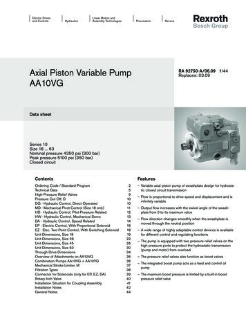
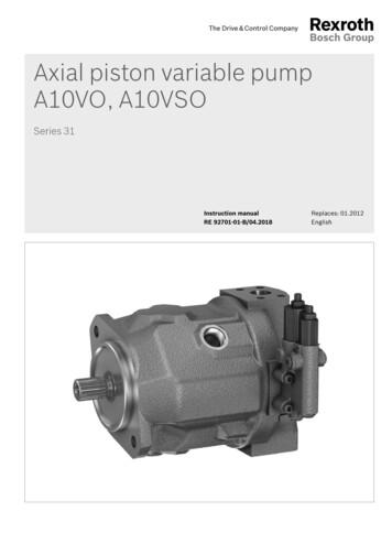
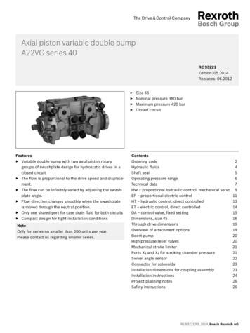
Electric Drivesand ControlsHydraulicsLinear Motion andAssembly TechnologiesPneumaticsServiceAxial Piston Variable MotorAA6VM (A6VM)RA 91604-A/07.09Replaces: 03.091/76TechnicalDatasheetdata sheetSeries 6SizeNominal pressure/Peak pressure5800 ps (400 bar) / 6500 psi (450 bar)28 to 200250 to10005100 psi (350 bar) / 5800 psi (400 bar)Open and closed circuitsFeaturesContentsOrdering code / Standard programTechnical dataHD - Hydraulic control, pilot-pressure relatedHZ - Hydraulic two-point controlEP - Electric control with proportional solenoidEZ - Electric two-point control, with switching solenoidHA - Automatic control, high-pressure relatedDA - Hydraulic control, speed relatedElectric travel direction valve (for DA, HA.R)Unit dimensions, size 28 (ISO Version)Unit dimensions, size 55 (SAE Version)Unit Dimensions, Size 80 (SAE Version)Unit dimensions, size 107 (SAE Version)Unit dimensions, size 140 (ISO Version)Unit dimensions, size 160 (SAE Version)Unit dimensions, size 200 (SAE Version)Unit dimensions, size 250 (SAE Version)Unit dimensions, size 355 (ISO Version)Unit dimensions, size 500 (ISO Version)Unit dimensions, size 1000 (ISO Version)Flush and boost pressure valveBVD counterbalance valve (sizes 55 to 160)Swivel angle indicator (Sizes 250 to 1000)Speed measurement (sizes 28 to 500)Connectors for solenoids (for EP, EZ, HA.U, HA.R, DA only)Installation instructionsGeneral 66687172747576– Variable motor with an axial tapered piston rotary group ofbent-axis design for hydrostatic drives in open and closedcircuits– For use in mobile and stationary application areas– The wide control range enables the variable motor to satisfythe requirement for high speed and high torque.– The displacement is infinitely variable from Vg max to Vg min 0.– The output speed depends on the flow of the pump and thedisplacement of the motor.– The output torque increases with the pressure differentialbetween the high and low pressure side and with increasingdisplacement.– Wide control range with hydrostatic transmission– Wide selection of control devices– Cost savings through elimination of gear shifts and possibilityof using smaller pumps– Compact, robust bearing system with long service life– High power density– Good starting characteristics– Low moment of inertia
2/76Bosch Rexroth AGAA6VMRA 91604-A/07.09Ordering code / Standard programAA6V0102M0304/ 63 W050607080910– V11–121314151617181920Hydraulic fluidMineral oil and HFD. HFD for sizes 250 to 1000 only in combination with long-life bearing "L" (without code)01 HFB, HFC hydraulic fluidSizes 28 to 200 (without code)Sizes 250 to 1000 (only in combination with long-life bearing "L")0203Axial piston unitBent-axis design, variableEVersion SAE28 55 80 107 140 160 200 250 355 500 1000– – – –– AA6VVersion ISO 1)1) 1)1)1)1) A6V28.200 250 355 500 1000 –Drive shaft bearingStandard bearing (without code)Long-life bearing– LOperation mode04 Motor (plug-in-motor A6VE see RE 91606)05Size Displacement Vg maxMin3 / revinControl deviceHydraulic control,pilot-pressure relatedcm3 /1.71 3.34 4.88 6.53 8.54 9.76 12.20 15.25 21.66 30.51 61.02rev 285580107 140 160 200 250 355 500 1000285580 107 140 160 200 250 355 500 1000 HD1Δp 365 psi (25 bar) HD2Δp 145 psi (10 bar)Δp 510 psi (35 bar)Hydraulic two-point controlElectric control, proportional––––– HD3––––– HZ ––– ––––HZ1– –––––––HZ312V EP124V EP212V ––– EZ1 ––– EZ212V– –––––––EZ324V– –––––––EZ4 HA1With pressure increase Δp 1450 psi (100 bar) HA206Without pressure increaseHydraulic control, speed relatedpSt /pHD 3/100,Hydraulic travel direction valvepSt /pHD 5/100,Hydraulic travel direction valve––––––– DA ––––DA112V ––––DA224V ––––DA3Electric travel directionvalve el. Vg max controlpSt /pHD 8/100,Hydraulic travel direction valve ––––DA412V ––––DA524V ––––DA6285580 107 140 160 200 250 355 500 1000 Electric travel directionvalve el. Vg max control07––24VElectric two-point controlAutomatic control,high-pressure related––Pressure control (only for HD, EP)Without pressure control (without code)Pressure control,Direct DDirect, with 2nd pressure setting 2)2)2)2)ERemote––––––– G
RA 91604-A/07.09Bosch Rexroth AGAA6VM3/76Ordering code / Standard programAA6V0102M0304/ 63 W0506070809– V1011Overriding HA control (for HA1, HA2 only)Without override (without code)08Hydraulic overrideElectric overrideElectric override electric travel direction valve–1228 55 131415161718192080 107 140 160 200 250 355 500 1000 T12V ––––U124V ––––U212V ––––R124V ––––R2Series09 Series 6, index 363Direction of rotation10 Viewed from shaft end, alternatingWSetting range for displacement 3)Vg min 0 to 0.7 Vg max (without code)11 Vg min 0 to 0.4 Vg maxVg min 0.4 Vg max to 0.8 Vg max28 55 80 107 140 160 200 250 355 500 1000––– –Vg max Vg max to 0.8 Vg max––––––– 1Vg max Vg max to 0.8 Vg max––––––– 2Seals12 FKM (fluor-caoutchouc)13VShaft endVersion SAE (AA6VM) Splined shaft ANSI B92.1a-197628–55 80 107 140 160 200 250 355 500 1000–– – –SVersion ISO ––––––––––A ––– ––– ZParallel keyed DIN 6885–––––––– PSplined shaft DIN 5480(A6VM)Mounting flangeVersion SAE(AA6VM)SAE J744 – 2-bolt28–55–80 107 140 160 200 250 355 500 1000––––––– –SAE J744 – 4-bolt– –Version ISO(A6VM)ISO 3019-2 – 4-hole –ISO 3019-2 – 8-hole––028–55 80 107 140 160 200 250 355 500 1000––510 – –7– – –––5170– – –––5207– – –––527370––– –––––––370For mounting a counterbalance valve 5)6) 3815Version ISO SAE flange ports01A/B, rear (metric threads)(A6VM)0– –––––38014Service line port 4)Version SAE SAE flange ports(AA6VM)A/B, rear (UN threads)SAE flange ports5152A/B side, opposite (UN threads)Port plate with pressure-relief valves,SAE flange ports02A/B side, opposite (metrics threads)SAE flange portsA/B side, opposite rearValvesWithout valveWith flush and boost pressure valve15 C ––– ––––––B–––––– H–––D0 ––– ––– 0107 ––– ––– 0170 ––– ––– 0207 ––– ––– 0270–––––––– 15007
4/76Bosch Rexroth AGAA6VMRA 91604-A/07.09Ordering code / Standard programAA6V0102M0304/ 63 W050607080910– V11Speed measurementWithout speed measurement (without code)7)Swivel angle indicatorWithout swivel angle indicator (without code)With Electric swivel angle indicator18 DEUTSCH - molded connector, 2-pin – with suppressor diodeHIRSCHMANN - connector – without suppressor diode1914151617181920 ––––D– F28 55 80 107 140 160 200 250 355 500 1000 –17 With optical swivel angle indicatorConnector for solenoids (only sizes 28 to 200) 8)DEUTSCH - molded connector, 2-pin – without suppressor diode1328 55 80 107 140 160 200 250 355 500 100016 Prepared for speed measurement (ID) 7)Prepared for speed measurement (HDD)–12––––––– V––––––– EEP1/2EZ1/2EZ3/4HA.U.HA.R.9)DA. P– ––– Q HStart of controlAt Vg min (standard for HA)28 55 80 107 140 160 200 250 355 500 1000 AAt Vg max (standard for HD, HZ, EP, EZ, DA) BStandard / special version9)(without code)Standard version20With attachment part combined-KSpecial version-SWith attachment part combined1)2)3)4)5)6)7)8)9)9)-SKISO-Version see RE 91604Supplied as standard with version D (sizes 250 to 1000)Please specify precise setting for Vg min and Vg max in plain text when ordering: Vg min . cm3, Vg max . cm3Metric fixing threadOnly possible in combination with HD, EP, HA controlComplete order recommended, counterbalance valve pages 68.70Complete order recommended, speed sensor page 72.73The HIRSCHMANN connector – without suppressor diode is only standard with sizes 250 to 1000 (without code)With HA.R1 and HA.R2 for the 2nd solenoid (DIA 45), the version with DEUTSCH molded connector is available on request.Adjustment data are included in the material number available on request preferred program not for new projects– not available
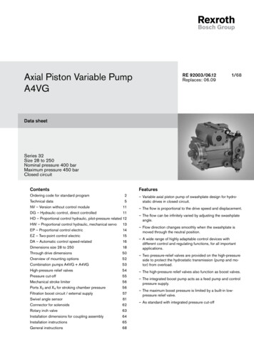
RA 91604-A/07.09Bosch Rexroth AGAA6VM5/76Technical dataSelection diagramWhen ordering, please indicate the used hydraulic 0o)(20o)(40o)(60o) (80o) (100o)7400(1600)170 (36)Nopt.1000(-20o)010VG 68VG 46VG 32VG 22The (A)A6VM variable motor is not suitable for operation withHFA. If HFB, HFC and HFD or environmentally acceptable hydraulic fluids are being used, the limitations regarding technicaldata and seals mentioned in RE 90221 and RE 90223 mustbe observed.(-40o)7000 (1600)5000 (1000)3000 (600)2000 (400)VGBefore starting project planning, please refer to our datasheets RE 90220 (mineral oil), RE 90221 (environmentally acceptable hydraulic fluids) and RE 90223 (HF hydraulic fluids)for detailed information regarding the choice of hydraulic fluidand application conditions.viscosity N SUS (mm2/s)Hydraulic fluid80 (16)(10)50Operating viscosity rangeFor optimum efficiency and service life, select an operating viscosity (at operating temperature) within the optimum range ofνopt optimum operating viscosity 80.170 SUS (16 to 36mm2/s)depending on the circuit temperature (closed circuit) and tanktemperature (open circuit).40(5)(-40o) (-25o) (-10o) (0o) (10o)-40o-13o 0o(30o)20o 40o 60o 80o(50o)(70o) (90o)42 (5)(115o)120o160o 195o240otmin -40oF fluid temperature range t in oF (oC)(-40oC)tmax 240oF( 115oC)Details regarding the choice of hydraulic fluidLimits of viscosity rangeThe limiting values for viscosity are as follows:Sizes 28 to 200:νmin 42 SUS (5 mm2/s)short-term (t 3 min)at max. perm. temperature of tmax 240 F ( 115 C)νmax 7400 SUS (1600 mm2/s)short-term (t 3 min)at cold start (p 435 psi / 30 bar, n 1000 rpm, tmin -40 F / -40 C)Only for starting up without load. Optimum operatingviscosity must be reached within approx. 15 minutes.Sizes 250 to 1000:νmin 60 SUS (10 mm2/s)short-term (t 3 min)at max. perm. temperature of tmax 195 F ( 90 C)νmax 4600 SUS (1000 mm2/s)short-term (t 3 min)at cold start (p 435 psi / 30 bar, n 1000 rpm, tmin -13 F / -25 C)Only for starting up without load. Optimum operatingviscosity must be reached within approx. 15 minutes.Note that the maximum hydraulic fluid temperature of 240 F(115 C) ( 195 F / 90 C for size 250 to 1000) must not be exceeded locally either (e.g. in the bearing area). The temperaturein the bearing area is - depending on pressure and speed - up to22 F (12 K) higher than the average case drain temperature.Special measures are necessary in the temperature range from 40 F and -13 F (-40 C and -25 C). Please contact us.For detailed information about use at low temperatures, seeRE 90300-03-B.The correct choice of hydraulic fluid requires knowledge of theoperating temperature in relation to the ambient temperature:in a closed circuit the circuit temperature, in an open circuit thetank temperature.The hydraulic fluid should be chosen so that the operating viscosity in the operating temperature range is within the optimumrange (νopt.) - the shaded area of the selection diagram. Werecommended that the higher viscosity class be selected ineach case.Example: At an ambient temperature of X C an operatingtemperature of 140 F (60 C) is set. In the optimum operatingviscosity range (νopt; shaded area) this corresponds to theviscosity classes VG 46 or VG 68; to be selected: VG 68.Please note:The case drain temperature, which is affected by pressure andspeed, is always higher than the circuit temperature or tanktemperature. At no point in the system may the temperature behigher than 240 F (115 C) for sizes 28 to 200 or 195 F (90 C)for sizes 250 to 1000.If the above conditions cannot be maintained due to extremeoperating parameters, we recommend flushing the case at portU or using a flush and boost pressure valve (see pages 66-67).
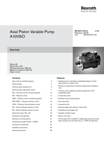
6/76Bosch Rexroth AGAA6VMRA 91604-A/07.09Technical dataFiltrationShaft seal ringThe finer the filtration, the higher the cleanliness level of the hydraulic fluid and the longer the service life of the axial piston unit.Permissible pressure loadTo ensure functional reliability of the axial piston unit, the hydraulic fluid must have a cleanliness level of at least20/18/15 according to ISO 4406.At very high hydraulic fluid temperatures (195 F to max. 240 F /90 C to max. 115 C) at least cleanliness level19/17/14 according to ISO 4406 is required.The service life of the shaft seal ring is affected by the speed ofthe motor and the case drain pressure. It is recommended that theaverage, continuous case drain pressure at operating temperature45 psi (3 bar) absolute not be exceeded (max. permissible casedrain pressure 90 psi (6 bar) absolute at reduced speed, see diagram). Short-term (t 0.1 s) pressure spikes of up to 145 psi (10bar) absolute are permitted. The service life of the shaft seal ringdecreases with an increase in the frequency of pressure spikes.If the classes specified above cannot be maintained, please contact us.The case pressure must be equal to or greater than the externalpressure on the shaft seal ring.Operating pressure rangeSizes 28 to 200Maximum pressure on port A or B(pressure data in according to DIN 24312)psibarNominal pressure pN 5800 psi (400 bar)*Peak pressure pmax 6500 psi (450 bar)*Total pressure (press. A press. B) pmax 10150 psi (700 bar)*) Size 80: pN 5100 psi (350 bar), pmax 5800 psi (400 bar)for sizes 250 to 1000Perm. pressure pabs. max.90for sizes 28 to 200(6)Size 28756045 Sizes 107, 140In cases of pulsating loading above 4550 psi (315 bar), we recommend the version with splined shaft Z (sizes 250 to 1000).A to B(1)4000No limit to minimum speed nmin. If uniformity of motion is required, speed nmin must not be less than 50 rpm. See table ofvalues on page 7 for maximum speed.Long-Life bearing (sizes 250 to 1000)For long service lif
2/76 Bosch Rexroth AG AA6VM RA 91604-A/07.09 Ordering code / Standard program Hydraulic fluid 01 Mineral oil and HFD. HFD for sizes 250 to 1000 only in combination with long-life bearing "L" (without code) HFB, HFC hydraulic fluid Sizes 28 to 200 (without code) Sizes 250 to 1000 (only in combination with long-life bearing "L") E Axial piston unit 28 55 80 107 140 160 200 250 355 500 1000 02 .