Transcription
Electric Drivesand ControlsHydraulicsLinear Motion andAssembly TechnologiesPneumaticsA10VO VariableDisplacement Piston PumpTechnical Information ManualThe Drive & Control CompanyService
A10VO PISTON PUMP MANUAL-MODULE 3AReproduction or use of editorial or pictorial content in any manner isprohibited without the express permission of:BOSCH REXROTH CANADA CORP.While every precaution has been taken in the preparation of this manual,the publisher assumes no responsibility for errors or omissions. Neither isany liability assumed for damages resulting in the misuse of the printedmaterial contained herein.First Edition 1996Revised Edition 2006Printed in Canada for:Bosch Rexroth Canada Corp.3426 Mainway DriveBurlington, OntarioCanada L7M 1A6Phone:Fax:(905) 335-5511(905) 335-9859Toll Free: 1-877-266-78111-877-COMPU-11Bosch Rexroth Canada Corp. 3426 Mainway Dr. Burlington, ON L7M 1A8 www.boschrexroth.ca16/06/2006Page 2 of 23
A10VO PISTON PUMP MANUAL-MODULE 3ATABLE OF CONTENTSFEATURES. 4FUNCTIONAL PURPOSE . 4DESCRIPTION . 6SPECIFICATIONS. 7Pressure . 7R.P.M . 7Case Drain. 7OPERATING CONDITIONS. 7Operating Viscosity. 7Recommended Filtration . 7Inlet Conditions . 7Leakage Line . 8Direction of Rotation . 8DFR CONTROL. 9CONTROL VALVE ASSEMBLY . 10Identification Drawing . 10Pressure Regulation . 10Flow Regulation . 11PUMP PERFORMANCE TEST . 11TEST EQUIPMENT . 12Gauge Test Port Kit . 12PORT SIZES . 12OPTIONAL ACCESSORIES . 13Low Oil Shut–Off Block. 13UNIT DIMENSIONS . 14STANDARD MODELS USED. 22STANDARD SPARE PARTS. 23Replacement Pump Control Valve . 23Replacement Seal Kits . 23Split Flanges . 23Bosch Rexroth Canada Corp. 3426 Mainway Dr. Burlington, ON L7M 1A8 www.boschrexroth.ca16/06/2006Page 3 of 23
A10VO PISTON PUMP MANUAL-MODULE 3AFEATURES High Efficiency through load sensing ( fuel savings)Maximum Pressure Control Built InLong Service LifeLarge Range of Flow Rates AvailableLow Noise LevelCast Iron ConstructionStandard Mounting Flange DimensionsStandard Drive Shaft DimensionsDirect Engine Mount or PTO Drive CapabilityFUNCTIONAL PURPOSEThis pump is preferred over a fixed displacement (gear) pump. A fixed displacement pumpdelivers a set volume of oil for each revolution of its drive shaft. Any of this fluid flow that is notrequired, by the hydraulic system to do work, is sent back to the oil reservoir over a restriction.This oil flow times the pressure difference (between the system and the reservoir) is power thathas been drawn from the engine and is now being turned into heat. The heat generated is a directindication of fuel wasted and of unnecessary wear and tear on the hydraulic fluid, thus on thehydraulic system's mechanical components.On the other hand, this variable displacement pump monitors (senses) by way of a smallhydraulic line connecting it to the control valves – the power requirement (load) on your hydraulicsystem and provides just enough fluid flow and pressure to meet your system's immediate need.This means that the pump can be left running constantly and as your system's requirementchanges the pump will simply adjust itself accordingly. By doing this, energy is not wasted awayin the form of heat; translating into fuel savings for you and less wear and tear in your hydraulicsystem.An adjustable pressure limit (up to 4100 PSI) is also built onto the pump. It operates by reducingthe output flow – all the way to zero if necessary – keeping the pressure supply to your hydraulicsystem from ever going too high.Different maximum displacements (sizes) with standard mounting flanges, are available to matchthe needs of your system. Also, various combinations of drive shafts (splined or keyed), rotationdirections (left hand or right hand) and port locations (rear or side) can be chosen to facilitate yourparticular installation requirements (ie. direct engine mounting as well as transmission power takeoff mounting can be accommodated).Bosch Rexroth Canada Corp. 3426 Mainway Dr. Burlington, ON L7M 1A8 www.boschrexroth.ca16/06/2006Page 4 of 23
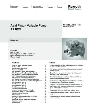
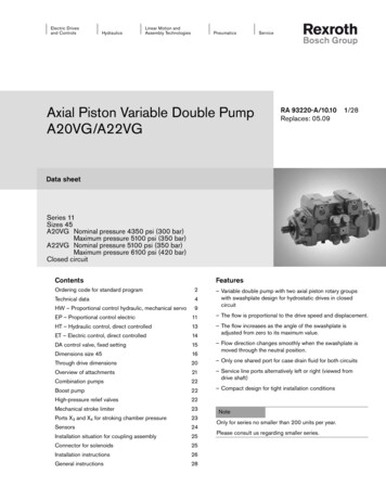
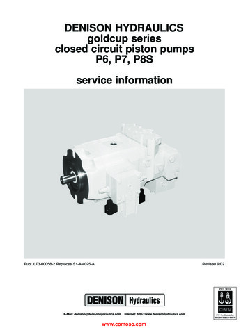
A10VO PISTON PUMP MANUAL-MODULE 3AFUNCTIONAL PURPOSE CONTINUEDVariable displacement swash plate design piston pump.1. Housing2. Control Piston3. Drive Shaft4. Swash Plate5. Control Valve Assembly6. Pistons (x7)Bosch Rexroth Canada Corp. 3426 Mainway Dr. Burlington, ON L7M 1A8 www.boschrexroth.ca16/06/2006Page 5 of 23
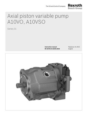
A10VO PISTON PUMP MANUAL-MODULE 3ADESCRIPTIONAxial piston pumps model A10V0 are swash plate design variable displacement pumps. Asillustrated by the picture under functional purpose they basically consist of a housing (1), controlpistons (2) located inside cylinder barrel, drive shaft (3), swash plate (4), a control valve assembly(5), and pistons (6)This piston pump smoothly and continuously varies its displacement (volumetric output – size), byaltering the angle of its swash plate. As your system operates, valves monitor the loads(pressures) on the actuators (cylinders and motors) and control the swash plate accordingly. Thegreater the angle of the swash plate, relative to the drive shaft, the further the pistons stroke inand out, therefore the greater the fluid flow.There are two control valves, located in a removable housing, bolted to the pump. The standardtype of control used is referred as flow and pressure compensation, type DFR. A simpleexplanation of how this works is described in the next paragraph. We have limited the explanationto one short paragraph as a detailed explanation goes beyond the technical requirements of thisGeneric Manual.The flow and pressure compensator control, also known as a load– sensing control, matchespump output flow and pressure to system demand. This control will automatically regulate thepump displacement to deliver the flow required to maintain a constant pressure drop across avalve spool or other flow limiting device. When there is no system demand, the pump stands by atzero flow and low pressure. When the system demands flow, the pump delivers only the flowrequired by the system, at a pressure required to move the load.To protect the system from infinite load pressures, the pressure compensator section of thecontrol will cause the pump to automatically de-stroke when the pre–adjusted maximum systempressure is reached.Bosch Rexroth Canada Corp. 3426 Mainway Dr. Burlington, ON L7M 1A8 www.boschrexroth.ca16/06/2006Page 6 of 23
A10VO PISTON PUMP MANUAL-MODULE 3ASPECIFICATIONSPressureThe pressure range for the standard models used as outlined under standard models is 4,100PSI maximum.R.P.M .NOTE: This figure is dependant on inlet conditions ensure you follow recommended installationguidelines as per commissioning instructions.Maximum speed (flooded suction)P/N 130985 (A10V028) 3000 rpmP/N 130272, 124691 and 117556 (A10V045) 2600 rpmP/N 103616 and 149312 (A10V071) 2200 rpmCase DrainEnsure pump mounted with case drain at highest to location to ensure pump prime is not lost andremains adequately lubricated. Maximum permissible pressure of the case drain can be 7 PSI(0.5 bar) maximum, higher than inlet pressure or suction pressure. Yet case pressure no higherthan 30 PSI (2 bar) absolute.OPERATING CONDITIONSOperating ViscosityOperating viscosity range: For optimum efficiency and pump life, we recommend that theoperating viscosity (at operating temperature) be selected in the range of opt optimumoperating viscosity 81.167 SUS (16.36 mm2/s) taking into consideration the reservoirtemperature range.Viscosity limits: The following values are valid for extreme operating conditions of short duration. min 60 SUS (10 mm2/s) for short periods at max. permissible drainage oil temperature of94º F (90ºC) max 4635 SUS (1000 mm2/s) for short periods upon cold start.Recommended FiltrationIn order to guarantee reliable function, both return and pressure filters should have 10 micron minInlet Conditions(Suction Line)The suction line, pipe or hose, should be as short and straight as possible. The pipe sectionshould be such that the negative pressure at the suction port never falls below 11.6PSI (abs.) (0,8bar) and never rises above 29PSI (abs.) (2 bar). Make sure connection points are airtight and thathoses are sufficiently pressure resistant against external air pressure. Use plastic hoses withsupporting mesh. Make sure there are no kinks in the hose when installing.Bosch Rexroth Canada Corp. 3426 Mainway Dr. Burlington, ON L7M 1A8 www.boschrexroth.ca16/06/2006Page 7 of 23
A10VO PISTON PUMP MANUAL-MODULE 3ALeakage Line(Case Drain)Leakage lines should be laid out so that the housing always remains filled with oil and the ingressof air at the radial seal is prevented even during long periods of in-operation. The leakage line justalways enter the tank (Reservoir) below the minimum oil level.Direction of RotationIs always defined as viewed on the drive shaft and indicated by a directional arrow. It is notpossible to change the direction of rotation of the drive without conversion of the pump.Bosch Rexroth Canada Corp. 3426 Mainway Dr. Burlington, ON L7M 1A8 www.boschrexroth.ca16/06/2006Page 8 of 23
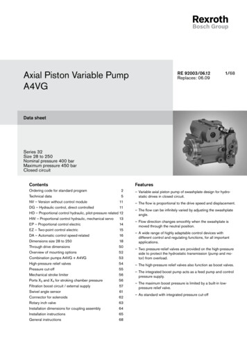
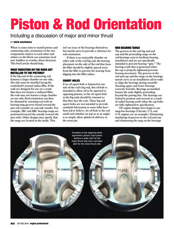
A10VO PISTON PUMP MANUAL-MODULE 3ADFR CONTROLBosch Rexroth Canada Corp. 3426 Mainway Dr. Burlington, ON L7M 1A8 www.boschrexroth.ca16/06/2006Page 9 of 23
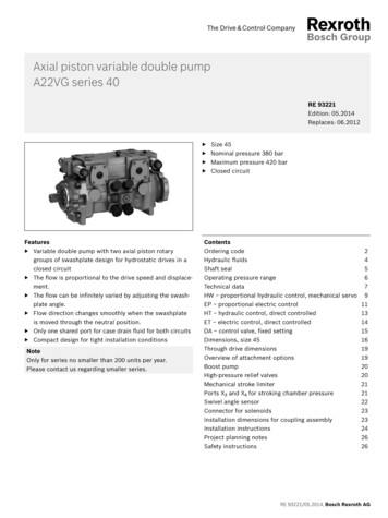
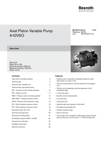
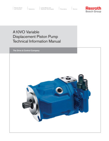
A10VO PISTON PUMP MANUAL-MODULE 3ACONTROL VALVE ASSEMBLYIdentification Drawing1.2.3.4.5.6.7.8.9.Flow regulationControl valve spoolsGauge test port From the pump's output portTo the pump's control pistonTo the pump's low pressure case then back to the reservoirConnection to the load sensing shuttle valve system in the main control valvesAdjustable command springsPressure RegulationControl valves and their adjustment screwsPressure RegulationMaximum system pressure setting. See module 2A Hydraulic Installation and Commissioningmanual for instructions for testing maximum pressure setting. These detailed instructions willassist you when changing pressure setting. The pressure is set with the pressure setting screw.1. Remove the cap nut with 17 mm external hexagon.2. Undo the lock nut with 17 mm external hexagon.3. Set the pressure range by turning the setting screw with hexagon socket head 4 mm.4. Lock the setting screw with lock nut, external hexagon 17 mm. Turning the setting screwclockwise increases the pressure. Turning the setting screw counter–clockwise reducesthe pressure. One turn of the setting screw corresponds to 50 bar pressure range 20 to250 bar.5. Screw on the cap nut with external hexagon 17 mm and tighten to a torque of Ma 8.5Nm. (186 Inch/Lb
BOSCH REXROTH CANADA CORP. While every precaution has been taken in the preparation of this manual, the publisher assumes no responsibility for errors or omissions. Neither is any liability assumed for damages resulting in the misuse of the printed material contained herein. First Edition 1996 Revised Edition 2006 Printed in Canada for: Bosch Rexroth Canada Corp. 3426 Mainway Drive Burlington .