Transcription
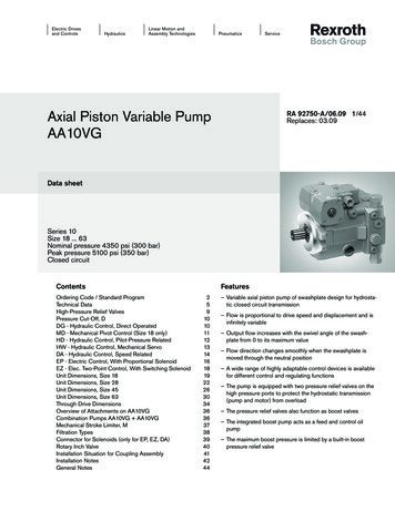
Axial Piston Variable PumpA4VGRE 92003/06.12Replaces: 06.091/68Data sheetSeries 32Size 28 to 250Nominal pressure 400 barMaximum pressure 450 barClosed circuitContentsFeaturesOrdering code for standard program2Technical data5NV – Version without control module11DG – Hydraulic control, direct controlled11HD – Proportional control hydraulic, pilot-pressure related 12HW – Proportional control hydraulic, mechanical servo13EP – Proportional control electric14EZ – Two-point control electric15DA – Automatic control speed-related16Dimensions size 28 to 25018Through drive dimensions50Overview of mounting options52Combination pumps A4VG A4VG53High-pressure relief valves54Pressure cut-off55Mechanical stroke limiter56Ports X3 and X4 for stroking chamber pressure56Filtration boost circuit / external supply57Swivel angle sensor61Connector for solenoids62Rotary inch valve63Installation dimensions for coupling assembly64Installation instructions65General instructions68–– Variable axial piston pump of swashplate design for hydrostatic drives in closed circuit.–– The flow is proportional to the drive speed and displacement.–– The flow can be infinitely varied by adjusting the swashplateangle.–– Flow direction changes smoothly when the swashplate ismoved through the neutral position.–– A wide range of highly adaptable control devices withdifferent control and regulating functions, for all importantapplications.–– Two pressure-relief valves are provided on the high-pressureside to protect the hydrostatic transmission (pump and motor) from overload.–– The high-pressure relief valves also function as boost valves.–– The integrated boost pump acts as a feed pump and controlpressure supply.–– The maximum boost pressure is limited by a built-in lowpressure relief valve.–– As standard with integrated pressure cut-off
2/68Bosch Rexroth AGA4VG Series 32 RE 92003/06.12Ordering code for standard programA4V G0102D030405/ 320607080910– N111213141516171819202122Axial piston unit01 Swashplate design, variable, nominal pressure 400 bar, maximum pressure 450 barA4VOperating mode02 Pump, closed circuitGSizes (NG)03 Geometric displacement, see table of values on page 8Control devicesWithout control moduleProportional controlhydraulic0408567190125 180 2502840567190125 180 250llllllllNVllllllllHD3mechanical servo1)llllllllHWProportional controlelectricU 12 V DCllllllllEP3U 24 V DCllllllllEP4Two-point control electricU 12 V DCllllllllEZ1U 24 V DCllllllllEZ2U 12 V DCllllllllDA1U 24 V DCllllllllDA2Hydraulic control, direct controlledllllllllDGPressure cut-off (see page 55)2840567190lllllNeutral position switch (only for HW, see page 13)Without neutral position switch (without code)2840567190llllllllNeutral position switchllllllllMechanical stroke limiter (see page 56)Without mechanical stroke limiter (without code)2840567190llllllllMechanical stroke limiter, externally adjustablellllllllPorts X3, X4 for stroking chamber pressure (see page 56)Without ports X3, X4 (without code)2840567190llllllllPorts X3, X4 for stroking chamber �2right–lllll–3Rleft–lllll–3Laccording to ISO 4925,no mineral oil––––l––4based on mineral oil––––l––8–lllll–705 Pressure cut-off (standard)0740pilot-pressure related p 6 to 18 barAutomatic control speed-related0628DA control valve (see page 17)Without DA control valveDA control valve fixed setting09DA control valve mechanicallyadjustable, with position leveractuating directionDA control valve fixed setting and braking inchvalve mounted, control with brake fluidDA control valve fixed setting, ports for pilot control device Available1)m On request– Not available125 180 250llDl125 180 250L125 180 250M125 180 250T Preferred programOn delivery, the position of the lever may differ from that shown in the brochure or drawing. If necessary, the position of thelever can be adjusted by the customer.
RE 92003/06.12 A4VG Series 32Bosch Rexroth AG3/68Ordering code for standard programA4V G0102D030405/ 320607080910– N111213141516171819202122Series10 Series 3, index 21132Directions of rotationViewed on drive shaftclockwiseRcounter-clockwiseLSeals12 NBR (nitrile-caoutchouc), shaft seal in FKM (fluor-caoutchouc)NDrive shafts (permissible input torques see page 9)Splined shaftfor single pumpDIN 5480for combination pump – 1st pump13 Splined shaftANSI �–––––llD2 4-hole–––lll––Fsuction port Sright2)3)4)5)6)suction port Sleftbottom28–top–125 180 250–––40 to 180 ithout through drivellllllllN00with through drivellllllllK.without through drivellllllllF00with through drivellllllllF.284056719016/32DP5)125 180 250125 180 2505/8 in9Tllllllll.017/8 in13T 16/32DP5)llllllll.021 in15T 16/32DP5)llllllll.041 in15T 16/32DP5)–l––––––.091 1/4 in14T ��––.738/16DP5)–––––lll.691 3/4 in 13T 8/16DP5)––––––ll.721 3/4 in 13T AvailableAlThrough drives (mounting options, see page 53)Flange SAE J7444)Coupling for splined shaft165-4 (E)llIntegrated boost pump152-2/4 (D)Z–2)–3)SAE flange ports A and B,same side17 127-2 (C)l–2)lSAE flange ports A and B,top and bottom82-2 (A)101-2 (B)l–3)Boost pumpWithout integrated boost pump16lfor combination pump – 1st pumpService line ports15l125 180 250for single pumpOnly for combination pump – 2nd pumpMounting flangesSAE J74428m On request– Not availableStandard for combination pump – 1st pump: shaft ZStandard for combination pump – 1st pump: shaft S2 2-hole; 4 4-holeCoupling for splined shaft according to ANSI B92.1aCoupling for splined shaft according to DIN 5480 Preferred program
4/68Bosch Rexroth AGA4VG Series 32 RE 92003/06.12Ordering code for standard programA4V G0102D030405/ 320607080910– N1112Setting range pValves (see page 54)High-pressure relief valve, pilot operated 100 to 420 bar with bypassHigh-pressure relief valve250 to 420 bar w/o bypass18 direct controlled, fixed settingwith bypass16171819202128–40–56–7190ll125 180 ��–––4with llDand cold start valve–llllll–KFilter mounted with cold start valveFilter mounted withinspection windowcold start valve andcontamination indicaelectric signaltor ernal supply (on version without integrated boost pump – N00, K.)llllllllESwivel angle sensor (see page 61)Without swivel angle sensor (without llllllllQPorts for external boost circuit filtration (Fe and Fa)Electric swivel angle sensormounted7)Connector for solenoids8) (see page 62)without suppressor diodeDEUTSCH molded21connector, 2-pinwith suppressor diode (only for EZ and DA)Standard / special versionStandard version125 180 250125 180 250without codecombined with attachment part or attachment pump-KSpecial version Available8)R125 180 250-Scombined with attachment part or attachment pump7)22lFiltration in the boost pump pressure line2215lFiltration boost circuit / external supply (see pages 57 to 60)Filtration in the boost pump suction line2014w/o bypass100 to 250 bar1913m On request– Not availablePlease contact us if the swivel angle sensor is used for controlConnectors for other electric components can deviate-SK Preferred program
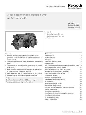
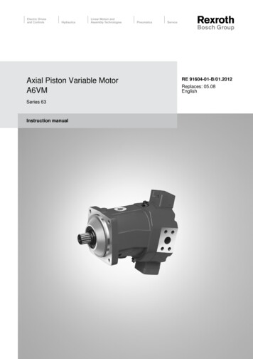
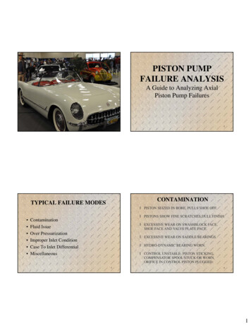
RE 92003/06.12 A4VG Series 32Bosch Rexroth AG5/68Technical dataHydraulic fluidDetails regarding the choice of hydraulic fluidBefore starting project planning, please refer to our datasheets RE 90220 (mineral oil), RE 90221 (environmentallyacceptable hydraulic fluids) and RE 90222 (HFD hydraulicfluids) for detailed information regarding the choice of hydraulicfluid and application conditions.The correct choice of hydraulic fluid requires knowledge of theoperating temperature in relation to the ambient temperature: ina closed circuit, the circuit temperature.The variable pump A4VG is not suitable for operation withHFA, HFB and HFC hydraulic fluids. If HFD or environmentallyacceptable hydraulic fluids are used, the limitations regardingtechnical data or other seals must be observed.Please contact us.Selection diagram-40 16001000600400-20 0 40 60 80 100 VG1006040Viscosity ν in mm2/s1600010VG 68VG 46VG 32VG 2220020 36νopt20The hydraulic fluid should be chosen so that the operatingviscosity in the operating temperature range is within theoptimum range (νopt see shaded area of the selection diagram).We recommended that the higher viscosity class be selectedin each case.Example: At an ambient temperature of X C, an operating temperature of 60 C is set in the circuit. In the optimum operatingviscosity range (νopt, shaded area), this corresponds to theviscosity classes VG 46 and VG 68; to be selected: VG 68.NoteThe case drain temperature, which is affected by pressure andspeed, can be higher than the circuit temperature. At no pointof the component may the temperature be higher than 115 C.The temperature difference specified below is to be taken intoaccount when determining the viscosity in the bearing.If the above conditions cannot be maintained due to extremeoperating parameters, please contact us.16105-40 -25 -10 0 10 30 50 70 90 5115 Temperature t in Ctmin -40 C Hydraulic fluid temperature rangetmax 115 CViscosity and temperature of hydraulic fluidViscosity [mm2/s]CommentTmin -50 CFactory preservation: up to 12 months with standard,Topt 5 C to 20 C up to 24 months with long-termTransport and storageat ambient temperature(Cold) start-up1)Temperaturenmax 1600TSt -40 Ct 3 min, without load (p 50 bar), n 1000 rpmDT 25 Kbetween axial piston unit and hydraulic fluidT -40 C to -25 Cat p 0.7 pnom, n 0.5 nnom and t 15 minTemperature differenceDT approx. 5 Kbetween hydraulic fluid in the bearing and at port TMaximum temperature115 Cin the bearing110 Cmeasured at port TT -25 C to 90 Cmeasured at port T,no restriction within the permissible dataTmax 110 Cmeasured at port T, t 3 min, p 0.3 pnomT 115 Csee page 7Permissible temperature differenceWarm-up phasen 1600 to 400Operating phaseContinuous operation n 400 to 10nopt 36 to 16Short-term operationFKM shaft seal1)1)nmin 7At temperatures below -25 C, an NBR shaft seal is required (permissible temperature range: -40 C to 90 C).
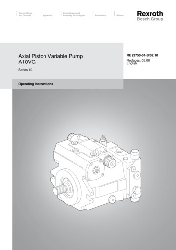
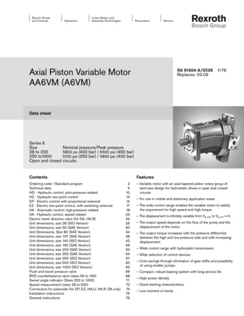
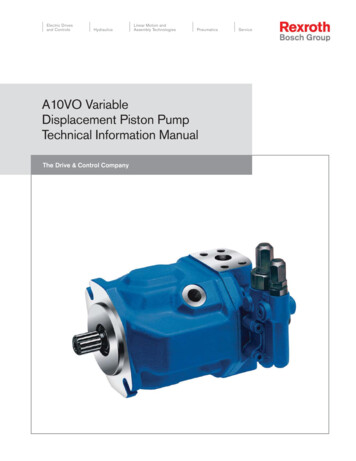
6/68Bosch Rexroth AGA4VG Series 32 RE 92003/06.12Technical dataFiltration of the hydraulic fluidShaft sealFiner filtration improves the cleanliness level of the hydraulicfluid, which increases the service life of the axial piston unit.Permissible pressure loadingDepending on the system and the application, for the A4VG,we recommendFilter cartridges β20 100.With an increasing differential pressure at the filter cartridges,the β value must not deteriorate.At very high hydraulic fluid temperatures (90 C to maximum115 C), a cleanliness level of at least 19/17/14 according toISO 4406 is necessary.If the above classes cannot be achieved, please contact us.For notes on filtration types, see page 57.The service life of the shaft seal is influenced by the speed ofthe axial piston unit and the case drain pressure (case pressure pG). The mean differential pressure of 2 bar between thecase and the ambient pressure may not be enduringly exceeded at normal operating temperature. For a higher differentialpressure at reduced speed, see diagram. Momentary pressurespikes (t 0.1 s) of up to 10 bar are permitted. The service lifeof the shaft seal decreases with an increase in the frequency ofpressure spikes.The case pressure must be equal to or higher than the ambientpressure.5Differential pressure Dp [bar]To ensure the functional reliability of the axial piston unit, a gravimetric analysis of the hydraulic fluid is necessary to determinethe amount of solid contaminant and to determine the cleanliness level according to ISO 4406. A cleanliness level of atleast 20/18/15 is to be maintained.NG250NG125NG40, 56NG180NG71, 90NG28432NG71NG90101000200030004000Speed n [rpm]NG28NG56 NG405000These values are valid for an ambient pressure pabs 1 bar.Temperature rangeThe FKM shaft seal may be used for case drain temperaturesfrom -25 C to 115 C.NoteFor application cases below -25 C, an NBR shaft sealis required (permissible temperature range: -40 C to 90 C). State NBR shaft seal in plain text when ordering.Please contact us.
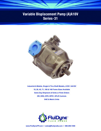
RE 92003/06.12 A4VG Series 32Bosch Rexroth AG7/68Technical dataOperating pressure rangeDefinitionPressure at service line port A or BNominal pressure pnomThe nominal pressure corresponds to the maximum designpressure.(operating with mineral oil)Nominal pressure pnom 400 bar absoluteMaximum pressure pmax 450 bar absoluteSingle operating period 10 sTotal operating period at nnom 300 hMinimum pressure (high-pressure side) 25 bar absoluteMinimum pressure (low-pressure side) 10 bar over pG(boost pressure setting must be higher, depending on system)Rate of pressure change RA max 9000 bar/spnomDpMinimum pressure (high-pressure side)Minimum pressure at the high-pressure side (A or B) which isrequired in order to prevent damage to the axial piston unit.Minimum pressure (low-pressure side)Minimum pressure at the low-pressure side (A or B) which isrequired in order to prevent damage to the axial piston unit.Rate of pressure change RAMaximum permissible rate of pressure rise and reduction during a pressure change over the entire pressure range.Single operating periodt1t2tnMaximum pressure pmaxNominal pressure pnomTime tBoost pumpPressure at suction port SContinuous pS min (ν 30 mm2/s) 0.8 bar absoluteShort-term, on cold start (t 3 min) 0.5 bar absoluteMaximum pS max 5 bar absoluteNominal pressure pSp nom 25 bar absoluteMaximum pressure pSp max 40 bar absoluteControl pressureTo
RE 92003/06.12 A4VG Series 32 Bosch Rexroth AG 5/68 Technical data Hydraulic fluid Before starting project planning, please refer to our data sheets RE 90220 (mineral oil), RE 90221 (environmentally acceptable hydraulic fluids) and RE 90222 (HFD hydraulic fluids) for detailed information regarding the choice of hydraulic fluid and application conditions. The variable pump A4VG is not .