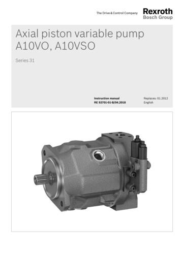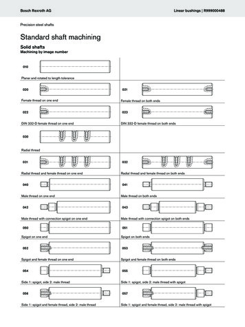
Transcription
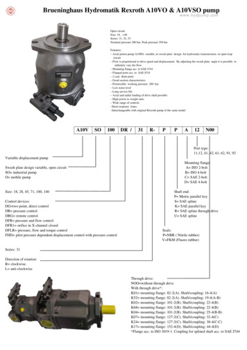
Brueninghaus Hydromatik Rexroth A10VO & A10VSO pumpwww.hydpump.comOpen circuitSize: 18 140Series: 31, 52, 53Nominal pressure 280 bar. Peak pressure 350 barFeatures:– Axial piston pump A10SO, variable, in swash plate design for hydrostatic transmissions in open loopcircuit– Flow is proportional to drive speed and displacement. By adjusting the swash plate angle it is possible toinfinitely vary the flow– Mounting flange acc. to SAE J744– Flanged ports acc. to SAE J518– 2 case drain ports– Good suction characteristics– Permissible working pressure 280 bar– Low noise level– Long service life– Axial and radial loading of drive shaft possible– High power to weight ratio– Wide range of controls–Short response times–Interchangeable with original Rexroth pump of the same modelA10VSO100DR /31R-PPA12N00Port type:11,12, 41, 42, 61, 62, 91, 92Variable displacement pumpSwash plate design variable, open circuitSO industrial pumpO mobile pumpSize: 18, 28, 45, 71, 100, 140Control devices:DG two point, direct controlDR pressure controlDRG remote controlDFR pressure and flow controlDFR1 orifice in X-channel closedDFLR pressure, flow and torque controlFHD pilot pressure dependent displacement control with pressure controlMounting flange:A ISO 2-boltB ISO 4-boltC SAE 2-boltD SAE 4-boltShaft end:P Metric parallel keyS SAE splineK SAE parallel keyR SAE spline through driveU SAE splineSeals:P NBR ( Nitrile rubber)V FKM (Fluoro rubber)Series: 31Direction of rotation:R clockwise.L anti-clockwiseThrough drive:NOO without through driveWith through drive*:K01 mounting flange: 82-2(A). Shaft/coupling: 16-4(A)K52 mounting flange: 82-2(A). Shaft/coupling: 19-4(A-B)K02 mounting flange: 101-2(B). Shaft/coupling: 22-4(B)K68 mounting flange: 101-2(B). Shaft/coupling: 22-4(B)K04 mounting flange: 101-2(B). Shaft/coupling: 25-4(B-B)K07 mounting flange: 127-2(C). Shaft/coupling: 32-4(C)K24 mounting flange: 127-2(C). Shaft/coupling: 38-4(C-C)K17 mounting flange: 152-4(D). Shaft/coupling: 44-4(D)*Flange acc. to ISO 3019-1. Coupling for splined shaft acc. to SAE J744
Rexroth A10VO & A10VSO Parts informationwww.hydpump.comVIEW: AITEM # 1: ROTARY GROUPITEM # 2: CONTROL-ASS.ITEM # 3: PUMP HOUSINGITEM # 4: END COVER-PORTSITEM # 5: CRADEL ASS.ITEM # 6: SHAFT - DRIVEITEM # 7: WASHERITEM # 8: ADJUSTING DISCITEM # 9: TAPPERED BRGITEM # 10: TAPPERED BRGITEM # 11: BEARING CRADLEITEM # 12: SEAL - SHAFTITEM # 13: O - RINGITEM # 14: O - RINGITEM # 15: SNAP RINGITEM # 16: CAP SCREWSITEM # 17: CONTROL ASS.ITEM # 18: PLUGITEM # 19: DOWEL PINSITEM # 20: PLUGITEM # 21: KEYITEM # 25: PLUGITEM # 22: COUPLINGITEM # 23: O - RINGITEM # 24: O - RINGVIEW: BITEM # 1: PISTONSITEM # 2: BARRELITEM # 3: LENS PLATEITEM # 4: RETAINER PLATEITEM # 5: RETAINING BALLITEM # 6: SPRINGITEM # 7: PRESSURE PINSITEM # 8: RETAINING RINGITEM # 1: CONTROL PISTONITEM # 2: PISTON GUIDEITEM # 3: COUNTER PISTONITEM # 4: PISTON GUIDEITEM # 5: SPRINGITEM # 6: LOCK NUTITEM # 7: ACCORN NUTITEM # 8: SCREW MAX. ADJ.ITEM # 9: RETAING CLIPVIEW: CITEM # 9: O-RING
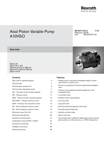
www.hydpump.comHydraulic FluidIn order to select the correct fluid, it is necessary to know the operating temperature in the tank (open circuit) in relation to the ambient temperature.The hydraulic fluid should be selected so that within the operating temperature range, the viscosity lies within the optimum range (νopt.); see shaded sectionof the selection diagram. We recommend that the higher viscosity grade is selected in each case.Example: at an ambient temperature of X C the operating temperature in the tank is 60 C. In the optimum viscosity range νopt (shaded area), thiscorresponds to viscosity grades VG 46 or VG 68, VG 68 should be selected.Important: The leakage oil temperature is influenced by pressure and speed and is typically higher than the tank temperature. However max. Temperature atany point in the system may not exceed 115 C. Prior to project design, please see our data sheets RE 90220 (mineral oil) and RE 90221 (ecologicallyacceptable fluids) for detailed information on fluids and application conditions. When using ecologically acceptable fluids attention must be paid to possiblelimitations of the technical data.DG - two point, direct controlThe pump can be set to a minimum swivel angle by connecting an external switching pressure to port X. This will supply the control piston directly with controloil; a minimum pressure of 50 bars is required.DR - Pressure controlThe pressure control serves to maintain a constant pressure in the hydraulic system, within the control range of the pump. The pump therefore supplies onlythe amount of hydraulic fluid required by the actuators. Pressure can be sleeplessly set at the pilot valve.DRG - Pressure control, remoteA pressure relief valve may be externally piped to port X for remote control purposes. However it is not included in the scope of supply with the DRG control.The differential pressure at the DRG control spool is set as standard to 20 bar and this results in a pilot flow of 1, 5 L/min. If another setting is required, pleasestate this in clear text.DFR/DFR1-Pressure-flow controlIn addition to the pressure control function, the pump flow to the actuator may be varied by means of a differential pressure (eg. over an orifice or directionalcontrol valve). The pump supplies only the amount of fluid as required by the actuator. In the DFR1-valveDFLR - Pressure/flow/power controlIn order to achieve a constant drive torque with a varying operating pressure, the swivel angle and with it the output flow from the axial piston unit is varied sothat the product of flow and pressure remains constant.FHD - Displacement control, pilot pressure dependent, with pressure controlThe swivel angle of the pump, and hence the displacement or flow, is dependent on the pilot pressure p St X in port X.A constant pressure at 35 bars is required at port Y. An overriding pressure control is integrated, and can be sleeplessly set at the control valve.Rexroth A10VO, A10VSODisplacementcm 3 /r [ in 3 /r]Max Speed [rpm]FlowWeightgpm [L/min]kg 460/132
Brueninghaus Hydromatik Rexroth A10VO & A10VSO 18DFR/31L-PSC12K01-SO 31R-PKC62K01-SO 2N00-SO 00-S1413A10VSO18DFR/31R-PPA12N00-SO PSC62N00A10VSO18DFR1/31L-PSC62N00-SO 00A10VSO18DFR1/31L-PUC62N00-SO 13A10VSO18DFR1/31L-PUC62N00-SO PKC62K01-SO 00-SO 71DFLR/31R-PPA12K26-SO 74A10VSO71DFLR/31R-PPA12K26-SO 54A10
rexroth a10vo & a10vso parts information view: a item # 1: rotary group item # 2: control-ass. item # 3: pump housing item # 4: end cover-ports item # 5: cradel ass. item # 6: shaft - drive item # 7: washer item # 8: adjusting disc item # 9: tappered brg item # 10: tappered brg item # 11: bearing cradle item # 12: seal - shaft item # 13: o - ring item # 14: o - ring item # 15: snap ring item .