Transcription
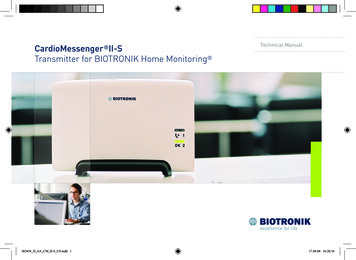
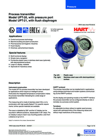
SmartLineTechnical InformationSTT700 SmartLine Temperature TransmitterSpecification34-TT-03-19, July 2017IntroductionPart of the SmartLine family of products, the SmartLineSTT700 is a high performance temperature transmitteroffering high accuracy and stability over a wide range ofprocess and ambient temperatures. SmartLine easily meetsthe most demanding needs for temperature measurementapplications.Best in Class Features: The STT700 is single or a dualinput temperature transmitter that supports millivolt,thermocouple and RTD sensors. It is available with eitherHART or DE protocol output.High performanceoDigital accuracy up to 0.15 Deg C for Pt100oStability up to 0.05% of URL per year for tenyearso500 mSec update time (single input)o1 Sec update time (dual input)Figure 1– SmartLine STT700 TemperatureTransmitter (HART) module shownwith dual input capabilityReliable measurementoBuilt in galvanic isolationoSensor break detectionoComprehensive on-board diagnostic capabilitiesoFull compliance to SIL 2/3 requirements.oAvailable with 4 year warrantyoSupports Namur 89 Wire breakAll transmitters are available with the above listedoDirect entry of Callendar-van Dusen coefficientsR0, α, δ and β for calibrated RTD sensors.output and communications protocol option.Lower Cost of OwnershipoUniversal inputoDual sensor optionoExternal zero, span, & configuration capabilityoPolarity insensitive loop wiringCommunications/Output Options:o4-20 mA DCoHART (version 7.0)oHoneywell Digitally Enhanced (DE)Mounting Options:oDirect sensor head mounting in DIN Form Aaluminum housing.oOther mounting options available include wall,pipe, DIN Rail or single compartment field housing.
2STT700 SmartLine Temperature TransmitterDescriptionPart of the SmartLine family of products, the SmartLine STT700 is a high performance temperature transmitter offeringhigh accuracy and stability over a wide range of process and ambient temperatures. The STT700 addresses the broadestmarket applications by providing a temperature transmitter that can meet the bulk of the industrial application needs. TheSTT700’s versatility, including the ability to select single or dual input, HART or DE protocol, with or without display, variousmounting configurations, and the ability to connect to 2, 3 or 4-wire sensors types, allows your site to standardize on a singleproduct and thus simplifying support and training.Configuration ToolsHand Held ConfigurationSmartLine transmitters feature two-way communication and configuration capability between the operator and the transmitter.This is accomplished via Honeywell’s field-rated Multiple Communication Configuration tool. The Honeywell handheld MCToolkit is capable of field configuring HART and DE devices and can also be ordered for use in intrinsically safe environments.All Honeywell transmitters are designed and tested for compliance with the offered communication protocols and are designedto operate with any properly validated handheld configuration device.Personal Computer ConfigurationHART Communicator Model 375, 475 or MC Toolkit for HART 7 Models.Field Device Manager (FDM) Software and FDM Express are also available for managing HART and DE device configurations(FDC).Smart Field Communicator (SFC) for DE ModelsDiagnosticsSmartLine transmitters all offer digitally accessible diagnostics which aid in providing advanced warning of possible failureevents minimizing unplanned shutdowns, providing lower overall operational costsSystem IntegrationoAll SmartLine products communications protocols meet all of the most current published standards for HARToSmartLine STT700 is fully compatible with Honeywell’s DE protocol.STT250 CompatibilityThe STT700 design allows it to easily replace an existing STT250 Temperature Transmitter. The STT700 physically will fit intoan existing STT250 mount and the STT700 offers the same functions as a STT250.
STT700 SmartLine Temperature Transmitter3Performance Specifications1,3Reference Accuracy 2 (conformance to /-3 Sigma)InputMaximum Range LimitsTypeRTD(2,3,4 wire)Pt100 ( 0.00385) C FDigitalAccuracyOutput D/AAccuracy( /-)(% of span) C%-200 to 450-328 to 8420.15-200 to 850-328 to 15620.25-200 to 450-328 to 8420.30-200 to 850-328 to 15620.40Ni 1205 (α 0.00672)-80 to 260-112 to 5000.12Pt505 ( 0.00391)-200 to 450-328 to 8420.32-200 to 600-328 to 11120.55Pt200 ( .025Edison Curve #70.025GOST 6651-940.025GOST 6651-94Pt1005 ( 0.00391)-200 to 450-328 to 8420.16-200 to 600-328 to 11120.27Cu 505 (α 0.00426)-50 to 200-58 to 3920.420.025GOST 6651-94Cu 1005 (α 0.00426)-50 to 200-58 to 3920.500.025GOST 6651-94Cu505 (α 0.00428)-200 to 200-328 to 3920.550.025GOST 6651-94Cu1005 (α 0.00428)-200 to 200-328 to 3920.320.025GOST 6651-94 C F C%ThermocouplesBC5EJKNRSTL5550 to 18201022 to 33081.00200 to 1820392 to 33083.000 to 165032 to 30021.200 to 230032 to 41721.700 to 100032 to 18320.30-328 to 18320.6032 to 14720.30-200 to 1200-200 to 21920.70-120 to 1370-191 to 24980.60-200 to 1370-328 to 24980.90-200 to 10000 to 80032 to 23720.40-200 to 13000 to 1300-328 to 23721.50500 to 1760-58 to 32000.60-50 to 1760-58 to 32001.00500 to 1760-58 to 32000.60-50 to 1760-58 to 32001.00-100 to 400-148 to 7520.30-250 to 400-418 to 7520.50-0 to 800-200 to 800-32 to 14720.50-328 to 14720.900.025ANSI / ASTM E-230 (ITS-90)0.025ANSI / ASTM E-230 (ITS-90)0.025ANSI / ASTM E-230 (ITS-90)0.025ANSI / ASTM E-230 (ITS-90)0.025ANSI / ASTM E-230 (ITS-90)0.025ANSI / ASTM E-230 (ITS-90)0.025ANSI / ASTM E-230 (ITS-90)0.025ANSI / ASTM E-230 (ITS-90)0.025ANSI / ASTM E-230 (ITS-90)0.025GOST R 8.585-2001
4STT700 Smart TemperatureOther InputTypesDigitalMaximum Range LimitsAccuracyOutput D/AAccuracy( /-)(% of span)Millivolts-7 to 22 mV0.010 mV0.025Millivolts-20 to 125 mV0.015 mV0.025Ohms0 to 500 Ohms0.35 Ohms0.025Ohms0 to 2000 Ohms0.50 Ohms0.025Standards1. Digital Accuracy is accuracy of the digital value accessed by the Host system and the handheld communicator2. Total analog accuracy is the sum of digital accuracy and output D/A Accuracy3. Output D/A Accuracy is applicable to the 4 to 20 mA Signal output4. For TC inputs, CJ accuracy shall be added to digital accuracy to calculate the total digital accuracy5. Not available in DE transmitters.6. Japanese Pt100J ( 0.003916) may be obtained by using the CVD algorithm with Pt100D.Differential Temperature MeasurementSmartLine STT700 Temperature supports differential temperature measurements for dual input transmitters.When the loop current mode is set to "Differential" then the input range is from A to B for sensor 1 & 2 whereA Sensor 1 Minimum - Sensor 2 MaximumB Sensor 1 Maximum - Sensor 2 MinimumDigital Accuracy for differential temperature measurement If both input types are the same, then the digital accuracy equals 1.5 times the worst case accuracy for that inputtype. If the input types are different, then the digital accuracy equals the sum of the worst case sensor 1 and sensor 2accuracies. For example, assume that input 1 is a J T/C and input 2 is an R T/C. Assume that the desiredoperating range is between 0 and 400 C. The digital accuracy for a J T/C in this range is 0.30 C and the digitalaccuracy for an R T/C in this range is 1.00 C. Therefore, the worst case digital accuracy would be 1.30 C.Callendar - Van Dusen Algorithm (CVD)The easy to use Callendar - Van Dusen (CVD) algorithm allows the use of calibrated platinum RTD sensors to increase theoverall system accuracy. Simply enable the algorithm and then enter the four CVD coefficients supplied with the calibratedRTD sensor into the transmitter. Honeywell can preprogram the CVD constants at the factory when the CustomConfiguration option is selected and the CVD constants are supplied at order entry.Performance under Rated Conditions – All modelsParameterDescriptionInput Span Adjustment RangeNo limits to adjustments within the maximum range except minimum span limit of 1engineering unitTwo-wire, 4 to 20 mAHART 7 protocol compliantHoneywell Digitally Enhanced (DE) protocol compliantHoneywell Standard:NAMUR NE 43 Compliance:Normal Limits:3.8 – 20.8 mA3.8 – 20.5 mAFailure Mode: 3.6 mA and 21.5 mA 3.6 mA and 21.5 mA 0.025 % span0.005 % span per volt.Analog OutputDigital Communications:Output Failure ModesOutput AccuracySupply Voltage EffectTransmitter Turn on Time(includes power up & testalgorithms)HART or DE: 6 sec.
STT700 Smart TemperatureAnalog InputResponse Time(delay time constant)Update timeDamping Time ConstantAmbient Temperature EffectCold Junction AccuracyTotal Reference AccuracySensor BurnoutVibration EffectElectromagnetic CompatibilityIsolation5Stability: 0.05% of URL per year for 10 yearsMaximum Lead Wire Resistance:Thermocouples and millivolts: 25 ohms/legRTD and ohms: 25 ohms/legAnalog Output500 mSec to reach 96% of final value with 0 seconds damping500 mSec for Single Input Units1 Sec for Dual Input UnitsHART: Adjustable from 0 to 102 seconds in 0.1 increments. Default: 0.50 secondsDE: Discrete values 0.0, 0.3, 0.7, 1.5, 3.1, 6.3, 12.7, 25.5, 51.1, 102.3 seconds.Default: 0.3 secondsDigital AccuracyFor all RTD (except Pt200) and 500 ohm Input Types: 0.017 ohms/ CFor RTD Pt200 and 2000 ohm Input Types: 0.034 ohms/C.Output D/A: 0.0045 % of span/ C 0.5 CDigital ModeDigital Accuracy C/J Accuracy (T/C input types only)Analog Mode (HART only)Digital Accuracy Output D/A Accuracy C/J Accuracy (T/C input types only)Example: Transmitter in Analog Mode with Pt100 sensor and 0 to 200 C rangeTotal Reference Accuracy 0.15 C (200 C / 100%) * 0.025% 0.20 CBurnout detection is user selectable. Upscale or down scale with critical status.Per IEC60770-1 field or pipeline, high vibration level (10-2000Hz: 0.21displacement/3g max acceleration)IEC 61326-3-12000 VDC (1400Vrms) Galvanic isolation between inputs and output.Performance under Rated Conditions – All modelsStray RejectionCommon ModeAC (50 or 60 Hz): 120 dB (with maximum source impedance of 100 ohms) or 1 LSB (least significant bit) whichever is greater with line voltage applied.DC: 120 dB (with maximum source impedance of 50 ohms) or a 1 LSB whichever isgreater with 120 VDC applied.DC (to 1 KHz): 50 dB (with maximum source of impedance of 50 ohms) or 1 LSBwhichever is greater with 50 VAC applied.Normal ModeAC (50 or 60 Hz): 60 dB (with 100% span peak-to-peak maximum)EMC ComplianceEN 61326-1 and EN 61326-3-1 (SIL)Lightning Protection OptionLeakage Current: 10 uA max @ 42.4 VDC 85 CImpulse rating: 8/20 uS5000 A ( 10 strikes)10/1000 uS200 A ( 300 strikes)Materials Specifications - All modelsParameterDescriptionTerminal Block and Module HousingLexan 500R (Polycarbonate, Glass Fiber Reinforced 10%)Connection ScrewsM3 Nickel Plated BrassWeight0.075 kg (0.2 lbs)10000 A (1 strike min.)
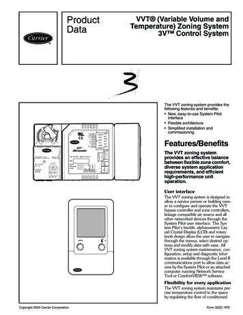
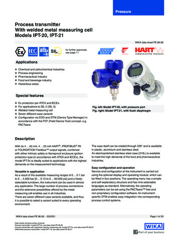
6STT700 Smart TemperatureOperating Conditions – All modelsParameterAmbient TemperatureHumidity %RHSupply VoltageLoad ResistanceReferenceCondition C F25 1 77 210 to 55Rated ConditionOperative Limits C-40 to 85 C-40 to 85 F-40 to 1850 to 100 F-40 to 185Transportation andStorage C F-55 to 120-67 to 2480 to 1000 to 100HART Models: 10.8 to 35.0 VDC at terminals (IS installations limited to 30 VDC)0 to 1,100 ohms (as shown in Figure 2)DE Models: 10.8 to 35 VDC at terminals (IS installations limited to 30 VDC)0 to 750 ohms (as shown in Figure 3)Figure 2 – HART Supply voltage and loop resistance chart & calculationsFigure 3 – DE Supply voltage and loop resistance chart & calculations
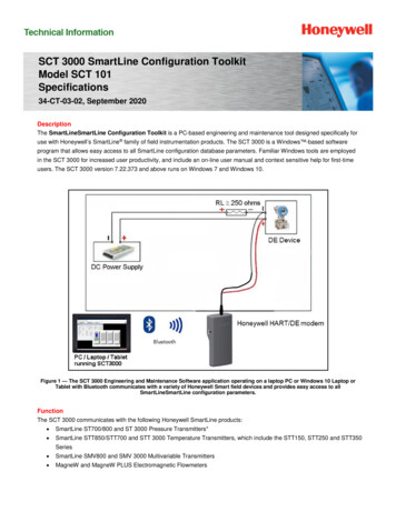
STT700 Smart Temperature7Physical Mounting and ConstructionThe STT700 Temperature Transmitter is designed to be mounted in a DIN Form A aluminum housing for direct installationwith the temperature sensor or can be provided in a remote pipe or wall mount housing. Details for the available housingsare in document #EN0I-6032. The STT700 temperature transmitter module can also be DIN rail mounted to a top hat or “G”rail via a clip.Integral MetersHoneywell’s Series STT700 temperature transmitters can be supplied with local or remote indication. An Engineering Units(EU) meter can be mounted integral to the transmitter inside the field mount housing. Order an integral meter as part of themodel number; Table III 1 . Order a remote meter as model RMA300. The EU meter displays temperature inengineering units. DE transmitters can use the EU Meter as long as they are configured to operate in the analog mode.Refer to document #34-ST-25-08D for more details.Lightning ProtectorThis device is designed to give the Smart temperature transmitter maximum protection against surges such as thosegenerated by lightning strikes. It mounts right on the top of the STT700 transmitter module, providing easy field wiring andalso protection for the EU meter if used.It mounts on the top of the STT700 transmitter module, providing easy field wiring. The compact mounting allows the use ofa variety of housings including the Honeywell explosion proof field mount housing. See Figure 4.Refer to document #34-TT-03-20, Lightning Protection spec for more details.The device can be used in both intrinsic safety and flame/explosion proof applications.Mounting & Dimensional DrawingsFigure 4 – STT700 transmitter module with lightning protection
8STT700 Smart TemperatureWiring DiagramsRTD Thermocouple, mV and Ohm ConnectionsFigure 5 - HART/DE Input Wiring Diagram for single sensor connectionFigure 6 – Wiring Diagram for HART Dual Sensor Connections
STT700 Smart Temperature9Approval Certifications:MSGCODEAGENCYF1FMApprovals TM(USA)F2(No EUMeter)FMApprovals TM(USA)F2(W/ EUMeter)FMApprovals TM(USA)TYPE OF PROTECTIONElectricalParametersAmbient TemperatureIntrinsically SafeT6: -40 oC to 40 oCCertificate: 17US0112XNote 2T5: -40 oC to 55 oCClass I Division 1, Groups A, B, C, D; T6 . T4T4: -40 oC to 70 oCClass I Zone 0 AEx ia IIC T6. T4 GaNon-Incendive and Zone 2 Intrinsically SafeCertificate: 17US0112XT6: -40 oC to 40 oCClass I, Division 2, Groups A, B, C, D; T6. T4Note 1T5: -40 oC to
0.025 ANSI / ASTM E-230 (ITS-90) T -100 to 400 -148 to 752 -250 to 400 -418 to 752 0.30 0.50 0.025 ANSI / ASTM E-230 (ITS-90) L5-0 to 800 -32 to 1472 -200 to 800 -328 to 1472 0.50 0.90 0.025 GOST R 8.585-2001 . 4 STT700 Smart Temperature 1. Digital Accuracy is accuracy of the digital value accessed by the Host system and the handheld communicator 2. Total analog accuracy is the sum of


![Merlin@home Transmitter [RF] [symbol update] [RED comp .](/img/10/7bd6c35e-42f6-4c21-be52-037b05000831.jpg)