Transcription
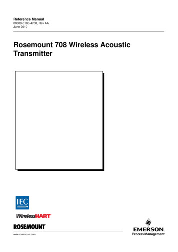
Reference Manual00809-0100-4708, Rev AAJune 2010Rosemount 708 Wireless AcousticTransmitterwww.rosemount.com
Reference Manual00809-0100-4708, Rev AAJune 2010Rosemount 708Rosemount 708 WirelessAcoustic TransmitterRosemount 708 Hardware RevisionHART Device RevisionField Communicator Field Device Revision11Dev vX, DD vXNOTICERead this manual before working with the product. For personal and system safety, and foroptimum product performance, make sure to thoroughly understand the contents beforeinstalling, using, or maintaining this product.The United States has two toll-free assistance numbers and one international number.Customer Central1 800 999 9307 (7:00 a.m. to 7:00 p.m. CST)National Response Center1 800 654 7768 (24 hours a day)Equipment service needsInternational1 952 906 8888The products described in this document are NOT designed for nuclear-qualifiedapplications.Using non-nuclear qualified products in applications that require nuclear-qualified hardwareor products may cause inaccurate readings.For information on Rosemount nuclear-qualified products, contact an Emerson ProcessManagement Sales Representative.
Reference Manual00809-0100-4708, Rev AAJune 2010Rosemount 708Explosions could result in death or serious injury:Installation of this transmitter in an explosive environment must be in accordancewith the appropriate local, national, and international standards, codes, andpractices. Please review the approvals section of the 708 Reference Manual for anyrestrictions associated with a safe installation. Before connecting a Field Communicator in an explosive atmosphere, ensure theinstruments are installed in accordance with intrinsically safe or non-incendivefield wiring practicesProcess leaks may cause harm or result in death: Install and tighten process connectors before applying pressureElectrical shock can result in death or serious injury: Avoid contact with the leads and terminals. High voltage that may be present onleads can cause electrical shockNOTICEThe Rosemount 708 and all other wireless devices should be installed only after theSmart Wireless Gateway has been installed and is functioning properly. Wirelessdevices should also be powered up in order of proximity from the Smart WirelessGateway, beginning with the closest. This will result in a simpler and faster networkinstallation.NOTICEShipping considerations for wireless products:The unit was shipped to you without the power module installed. Please remove the powermodule prior to shipping.Each power module contains one “D” size primary lithium battery. Primary lithium batteriesare regulated in transportation by the U. S. Department of Transportation, and are alsocovered by IATA (International Air Transport Association), ICAO (International Civil AviationOrganization), and ARD (European Ground Transportation of Dangerous Goods). It is theresponsibility of the shipper to ensure compliance with these or any other localrequirements. Please consult current regulations and requirements before shipping.The power module with the wireless unit contains one "D” size primary lithium/thionyl chloridebatteries. Each battery contains approximately X.X grams of lithium. Under normal conditions,the battery materials are self-contained and are not reactive as long as the batteries and the packintegrity are maintained. Care should be taken to prevent thermal, electrical or mechanicaldamage. Contacts should be protected to prevent premature discharge.Battery hazards remain when cells are discharged.Power modules should be stored in a clean and dry area. For maximum battery life, storagetemperature should not exceed 30 C.The power module has surface resistivity greater than one gigaohm and must be properlyinstalled in the wireless device enclosure. Care must be taken during transportation to and fromthe point of installation to prevent electrostatic charge build-up.
Reference Manual00809-0100-4708, Rev AAJune 2010Rosemount 708Table of ContentsSECTION 1OverviewSafety Messages . . . . . . . . . . . . . . . . . . . . . . . . . . . . . . . . . . . . . . . .Overview . . . . . . . . . . . . . . . . . . . . . . . . . . . . . . . . . . . . . . . . . . . . . . .Considerations . . . . . . . . . . . . . . . . . . . . . . . . . . . . . . . . . . . . . . . . . .Service Support . . . . . . . . . . . . . . . . . . . . . . . . . . . . . . . . . . . . . . . . .Product Recycling/Disposal . . . . . . . . . . . . . . . . . . . . . . . . . . . . . . . .1-11-21-31-41-5SECTION 2ConfigurationSafety Messages . . . . . . . . . . . . . . . . . . . . . . . . . . . . . . . . . . . . . . . .Device Sensor Configuration . . . . . . . . . . . . . . . . . . . . . . . . . . . . . . .Device Network Configuration . . . . . . . . . . . . . . . . . . . . . . . . . . . . . .Remove Power Module. . . . . . . . . . . . . . . . . . . . . . . . . . . . . . . . . . . .2-12-12-22-5SECTION 3MountingSafety Messages . . . . . . . . . . . . . . . . . . . . . . . . . . . . . . . . . . . . . . . . 3-1Mounting . . . . . . . . . . . . . . . . . . . . . . . . . . . . . . . . . . . . . . . . . . . . . . . 3-2SECTION 4CommissioningSafety Messages . . . . . . . . . . . . . . . . . . . . . . . . . . . . . . . . . . . . . . . . 4-1Verify Operation . . . . . . . . . . . . . . . . . . . . . . . . . . . . . . . . . . . . . . . . . 4-2SECTION 5Operation andMaintenanceSafety Messages . . . . . . . . . . . . . . . . . . . . . . . . . . . . . . . . . . . . . . . . 5-1Power Module Replacement. . . . . . . . . . . . . . . . . . . . . . . . . . . . . . . . 5-1APPENDIX ASpecifications andReference DataSpecifications . . . . . . . . . . . . . . . . . . . . . . . . . . . . . . . . . . . . . . . . . . . A-1Dimensional Drawings . . . . . . . . . . . . . . . . . . . . . . . . . . . . . . . . . . . . A-3Ordering Information . . . . . . . . . . . . . . . . . . . . . . . . . . . . . . . . . . . . . . A-4APPENDIX BProductCertificationsTOC-1
Reference ManualRosemount 708TOC-200809-0100-4708, Rev AAJune 2010
Reference Manual00809-0100-4708, Rev AAJune 2010Section 1Rosemount 708OverviewSafety Messages . . . . . . . . . . . . . . . . . . . . . . . . . . . . . . . . . page 1-1Overview . . . . . . . . . . . . . . . . . . . . . . . . . . . . . . . . . . . . . . . page 1-2Considerations . . . . . . . . . . . . . . . . . . . . . . . . . . . . . . . . . . page 1-3Service Support . . . . . . . . . . . . . . . . . . . . . . . . . . . . . . . . . page 1-4Product Recycling/Disposal . . . . . . . . . . . . . . . . . . . . . . . page 1-5SAFETY MESSAGESInstructions and procedures in this section may require special precautions toensure the safety of the personnel performing the operations. Information thatpotentially raises safety issues is indicated by a warning symbol ( ). Pleaserefer to the following safety messages before performing an operationpreceded by this symbol.WarningsFailure to follow these installation guidelines could result in death or serious injury: Only qualified personnel should perform the installationExplosions could result in death or serious injury. Before connecting a Field Communicator in an explosive atmosphere, makesure that the instruments are installed in accordance with intrinsically safe ornon-incendive field wiring practices Verify that the operating atmosphere of the transmitter is consistent with theappropriate hazardous locations certificationsElectrical shock could cause death or serious injury. Use extreme caution when making contact with the leads and terminals1-1
Reference Manual00809-0100-4708, Rev AAJune 2010Rosemount 708OVERVIEWManualThis manual is designed to assist in the installation, operation, andmaintenance of the Rosemount 702.Section 1: Overview Overview Considerations Service Support Product Recycling/DisposalSection 2: Configuration Device Sensor Configuration Device Network Configuration Remove Power ModuleSection 3: Mounting Mounting- Direct Mount Ground the TransmitterSection 4: Commissioning Verify Operation AMS Wireless ConfiguratorSection 5: Operation and Maintenance Power Module ReplacementSection A: Specifications and Reference Data Specifications Dimensional Drawings Ordering InformationSection B: Product CertificationsTransmitter1-2 Approved Manufacturing Locations Telecommunication Compliance FCC and IC European Union Directive Information Ordinary Location Certification for FM Hazardous Locations CertificatesFeatures of the Rosemount 708 include: An installation-ready solution that provides acoustic noise detection. Acoustic levels to verify the state of steam traps, pressure relief valves,condensers, and many others. Wireless output with 99% data reliability delivers rich HART data,protected by industry leading security Simple and easy installation practices currently being used for robustinstallations
Reference Manual00809-0100-4708, Rev AAJune 2010Rosemount 708CONSIDERATIONSGeneralThe acoustic transmitter detects either a noise or no noise along with atemperature. By using simple HART configuration, the Rosemount 708converts the noise and temperature status to a device status.Wireless ConsiderationsPower Up SequenceThe power module should not be installed on any wireless device until theSmart Wireless Gateway (“Gateway”) is installed and functioning properly.Wireless devices should also be powered up in order of proximity from theGateway, beginning with the closest. This will result in a simpler and fasternetwork installation. Enable Active Advertising on the Gateway to ensure thatnew devices join the network faster. For more information see the SmartWireless Gateway Manual (Document Number 00809-0200-4420).Antenna PositionThe antenna is internal to the acoustic transmitter. If best practices arefollowed, the antenna position will not matter in the wireless functionality.Field Communicator ConnectionsThe Power Module needs to be connected for the Field Communicator tointerface with the 708.Figure 1-1.MechanicalLocationWhen choosing an installation location and position, take into account accessto the transmitter.1-3
Reference Manual00809-0100-4708, Rev AAJune 2010Rosemount 708ElectricalPower ModuleThe Rosemount 708 Wireless transmitter is self-powered. The included powermodule contains one “D” size primary lithium/thionyl chloride battery. Eachbattery contains approximately X.X grams of lithium. Under normal conditions,the battery materials are self-contained and are not reactive as long as thebatteries and the power module are maintained. Care should be taken toprevent thermal, electrical, or mechanical damage. Contacts should beprotected to prevent premature discharge.Use caution when handling the power module, it may be damaged if droppedfrom heights in excess of 20 feet (6.10 m).EnvironmentalVerify that the operating atmosphere of the transmitter is consistent with theappropriate hazardous locations certifications.Temperature EffectsThe transmitter will operate within specifications for ambient temperaturesbetween -40 and 185 F (-40 and 85 C). Heat from the process is transferredfrom the switch to the transmitter housing. If the expected processtemperature is near or beyond specification limits, .add recommendationTemperature LimitsOperating Limit-40 to 185 F-40 to 85 CSERVICE SUPPORTStorage Limit-40 to 185 F-40 to 85 CTo expedite the return process outside of North America, contact yourEmerson Process Management representative,Within the United States, call the Emerson Process Management ResponseCenter toll-free number 1 800 654 7768. The center, which is available 24hours a day, will assist you with any needed information or materials.The center will ask for product model and serial numbers, and will provide aReturn Material Authorization (RMA) number. The center will also ask for theprocess material to which the product was last exposed.Individuals who handle products exposed to a hazardous substance can avoid injury if theyare informed of, and understand, the hazard. If the product being returned was exposed to ahazardous substance as defined by OSHA, a copy of the required Material Safety DataSheet (MSDS) for each hazardous substance identified must be included with the returnedgoods.SHIPPING CONSIDERATIONS FOR WIRELESS PRODUCTS (LITHIUMBATTERIES):The unit was shipped with the Power Module not installed. Please remove thePower Module from the unit before shipping.Primary lithium batteries (charged or discharged) are regulated duringtransportation by the U.S. Department of Transportation. They are also1-4
Reference Manual00809-0100-4708, Rev AAJune 2010Rosemount 708covered by IATA (International Air Transport Association), ICAO (InternationalCivil Aviation Organization), and ARD (European Ground Transportation ofDangerous Goods). It is the responsibility of the shipper to ensure compliancewith these or any other local requirements. Consult current regulations andrequirements before shipping.PRODUCTRECYCLING/DISPOSALRecycling of equipment and packaging should be taken into considerationand disposed of in accordance with local and national legislation/regulations.1-5
Reference ManualRosemount 7081-600809-0100-4708, Rev AAJune 2010
Reference ManualRosemount 7081-700809-0100-4708, Rev AAJune 2010
Reference ManualRosemount 7081-800809-0100-4708, Rev AAJune 2010
Reference Manual00809-0100-4708, Rev AAJune 2010Section 2Rosemount 708ConfigurationSafety Messages . . . . . . . . . . . . . . . . . . . . . . . . . . . . . . . . . page 2-1Device Sensor Configuration . . . . . . . . . . . . . . . . . . . . . . page 2-1Device Network Configuration . . . . . . . . . . . . . . . . . . . . . page 2-2Remove Power Module . . . . . . . . . . . . . . . . . . . . . . . . . . . page 2-5SAFETY MESSAGESInstructions and procedures in this section may require special precautions toensure the safety of the personnel performing the operations. Information thatpotentially raises safety issues is indicated by a warning symbol ( ). Pleaserefer to the following safety messages before performing an operationpreceded by this symbol.WarningsFailure to follow these installation guidelines could result in death or serious injury: Only qualified personnel should perform the installationExplosions could result in death or serious injury. Before connecting a Field Communicator in an explosive atmosphere, makesure that the instruments are installed in accordance with intrinsically safe ornon-incendive field wiring practices Verify that the operating atmosphere of the transmitter is consistent with theappropriate hazardous locations certificationsElectrical shock could cause death or serious injury. DEVICE SENSORCONFIGURATIONUse extreme caution when making contact with the leads and terminalsRemove the power module housing then connect to the HARTcommunication terminals for configuration.The Rosemount 708 will receive any HART communication from a handheldField Communicator, or AMS . When using a Field Communicator, anyconfiguration changes must be sent to the transmitter using the Send key(F2). AMS configuration changes are implemented when the Apply button isclicked.AMS Wireless ConfiguratorAMS is capable of connecting to devices directly, using a HART modem, orwith the Gateway. When configuring on the bench with a HART modem,double click the device icon, then choose the Configure/Setup tab (or rightclick and select Configure/Setup). Configure the device settings using theDirect Connection menu. When configuring with the Gateway, double click thedevice icon then choose the Configure/Setup tab (or right click and selectConfigure/Setup). Configure the device settings using the WirelessConnection menu.To check or change sensor configuration using a 475 Field Communicator,enter the following Fast Key Sequence: X, X, X.2-1
Reference ManualRosemount 708DEVICE NETWORKCONFIGURATION00809-0100-4708, Rev AAJune 2010To communicate with the Gateway, and ultimately the Information System, thetransmitter must be configured to communicate with the wireless network.Using a Field Communicator or AMS, enter the Network ID and Join Key sothey match the Network ID and Join Key of the Gateway and the otherdevices in the network. If the Network ID and Join Key are not identical, thetransmitter will not communicate with the network. The Network ID and JoinKey may be obtained from the Gateway on the Setup Network Settingspage on the web server. Using a 475 Field Communicator, the Network ID canbe configured by entering the Fast Key Sequence: X, X, X, X. The Join Keycan also be configured using a 475 Field Communicator with the Fast KeySequence: X, X, X, X.The final device network configuration piece is the Update Rate which, bydefault, is 1 minute. It can be changed at commissioning, or at any time, byusing AMS or the Gateway’s web server. The Update Rate should bebetween 4 seconds and 60 minutes. To change the Update Rate with a FieldCommunicator, use the Fast Key Sequence: X, X, X.If doing a bench top initial configuration, after completion remove the powermodule until installation. When the device is installed, insert he power moduleand close the housing cover securely. Always ensure a proper seal so thatpolymer touches polymer, but do not over tighten.Figure 2-1. 708 Power ModuleConnect the HART communication leads to the COMM terminals on thepower module.2-2
Reference Manual00809-0100-4708, Rev AAJune 2010Rosemount 708Figure 2-2. 475 FieldCommunicator ConnectionsFor HART communication, a 708 DD is required.2-3
Reference Manual00809-0100-4708, Rev AAJune 2010Rosemount 708HART Menu TreeFor ease of operation, changing setup, such as switch type, can be completedin several locations.Figure 2-3. Field Communicator Menu Tree1.2.3.4.5.Active AlertsCommunication StatusSensorSensor StatusLast Update Time1.2.3.4.5.1.2.3.4.Join Device to NetworkConfigure Update RateConfigure Discrete ApplicationConfigure Device DisplayNetwork IDJoin Device to Network Broadcast RatesConfigure Broadcast Power LevelPower ModePower Source1. Configure Discrete Application2. Discrete Input 13. Discrete Input 21. Configure Update Rate2. Message 13. Message 21. Discrete State2. Invert Option3. Sensor Serial Number1. Discrete State2. Invert Option3. Sensor Serial Number1. Guided Setup2. Manual Setup1.2.3.4.5.6.WirelessDiscrete SensorsElectronics TemperatureDevice InformationDevice DisplayOther1.2.3.4.5.1.2.3.4.5.6.1. Overview2. ConfigureElectronics TemperatureElectronics Temperature StatusUnitMaximumMinimumTagLong TagDeviceDiscrete Input 1Discrete Input 2Wireless3. Service Tools1. Mode1. Manufacturer2. Model3. Final Assembly Number4. Universal5. Field Device6. Software7. Hardware8. Descriptor9. Message10 Date11 Model Number I12 Model Number II13 Model Number III14 SI Unit Restriction15 Country16 Device ID1. Write Protect2. AC Power Filter3. Measurement and Status Log1. Sensor Serial Number1. Sensor Serial Number1. Active Alerts2. ine MaintenanceSimulate1.2.3.4.5.6.7.Discrete Input 1Discrete Input 2Electronics TemperatureElectronics temperature StatusSupply VoltageSupply Voltage StatusLast Update Time1.2.3.4.5.6.Join StatusCommunication StatusJoin ModeNumber of Available NeighborsNumber of Advertisements HeardNumber of Join Attempts1. Sensor Calibration2. Other1.2.3.4.2-4Discrete Input 1Discrete Input 2Electronics TemperatureSupply Voltage1. Clear Alert History1. Discrete Input 1 Sensor Wiring Offset2. Discrete Input 2 Sensor Wiring Offset1. Perform Master Reset2. Measurement History3. Advertise to New Devices1.2.3.4.5.ManufacturerDevice TypeDevice RevisionSoftware RevisionHardware Revision
Reference Manual00809-0100-4708, Rev AAJune 2010Fast Key SequenceRosemount 708Table 2-1 lists the fast key sequence for common transmitter functions.NOTE:The fast key sequences assume that DD Dev v1, DD v4 is being used.Table 2-1. 702 Fast KeySequenceFunctionKey SequenceDevice Information2, 2, 5, 3Guided Setup2, 1Manual Setup2, 2Wireless2, 2, 1Discr
AMS Wireless Configurator AMS is capable of connecting to devices directly, using a HART modem, or with the Gateway. When configuring on the bench with a HART modem, double click the device icon, then choose the Configure/Setup tab (or right click and select
