Transcription
40 METER (7MHz)CW TRANSMITTERRamsey Electronics Model No.QRP40THE RAMSEY QRP-40 IS AN AMAZING PERFORMERTHAT WILL WORK THE WORLD ON ABOUT A WATT!FOLKS OF ALL AGES HAVE SUCCESSFULLY BUILTAND ENJOYED THIS EASY, FUN KIT. Ideal for portable or travel fun VCXO design allows up to 5 KHz of tuning about the crystalfrequency Front panel switching of TWO channels and includes a crystal for7.040 MHz, the International QRP frequency Excellent and clean keying waveform Built-in antenna T-R switch Operates on 12 - 15 volts DC at 1/4 amp current Appoximately 1 Watt RF power Clear, concise step-by-step instructions carefully guide you to afinished kit that not only works - but you’ll also learn too! Proven design that has won many of awards for operators aroundthe country! Add our case and knob set for a finished ‘Pro’ look. Cases match allRamsey productsQRP-40 1
PARTIAL LIST OF AVAILABLE KITSRAMSEY TRANSMITTER KITS FM10A FM Stereo Transmitter FM100B Professional FM Stereo Transmitter FM25B Synthesized FM Stereo Transmitter AM25 Synthesized AM Transmitter AM1 AM TransmitterRAMSEY RECEIVER KITS FR1 FM Broadcast Receiver AR1 Aircraft Band Receiver AA7 Active Antenna SC1 Shortwave Converter SR2 Shortwave ReceiverRAMSEY HOBBY KITS SG7 Personal Speed Radar SS70 Speech Scrambler TT1 Telephone Recorder SP1 Speakerphone MD3 Microwave Motion Detector PH10 Peak hold Meter TFM3 Tri-Field MeterRAMSEY AMATEUR RADIO KITS DDF1 Doppler Direction Finder HR Series HF All Mode Receivers QRP Series HF CW Transmitters CW7 CW Keyer CPO3 Code Practice Oscillator QRP Power AmplifiersRAMSEY MINI-KITSMany other kits are available for hobby, school, scouts and just plain FUN. Newkits are always under development. Write or call for our free Ramsey catalog.40 METER CW TRANSMITTER KIT INSTRUCTION MANUALRamsey Electronics publication No. QRP40 Revision 1.3First printing: January 1995COPYRIGHT 1994 by Ramsey Electronics, Inc. 590 Fishers Station Drive, Victor, New York14564. All rights reserved. No portion of this publication may be copied or duplicated without thewritten permission of Ramsey Electronics, Inc. Printed in the United States of America.QRP-40 2
Ramsey Publication No. QRP40Price 5.00KIT ASSEMBLYAND INSTRUCTION MANUAL FORQRP40 40 METER CWTRANSMITTER KITTABLE OF CONTENTSIntroduction to the QRP40 . 4Understanding Power Levels . 5Circuit Description . 7Simplified Block Diagram . 8Parts List . 9Schematic Diagram . 10Parts Layout Diagram . 11Assembly Instructions . 12Crystal Oscillator Testing . 16Initial Tests . 17Verifying RF Power . 18Maximizing RF Power Output . 19Options for Finishing Project . 20Enclosure Ideas . 20Choosing Crystals . 20Troubleshooting Guide . 21Ramsey Kit Warranty . 22RAMSEY ELECTRONICS, INC.590 Fishers Station DriveVictor, New York 14564Phone (585) 924-4560Fax (585) 924-4555www.ramseykits.comQRP-40 3
INTRODUCTION:Most "QRP" transmitters are one-of-a-kind experimental circuits which takesome patience and fine-tuning to get clean keying and satisfactoryperformance. Most QRP building projects presume either unlimited radiojunkboxes with all the right coils and capacitors, or that you have a lot of timeon your hands to track down needed parts. And that is part of what ham radiocan be all about. The purpose of the Ramsey Electronics series of QRPtransmitters is to give our amateur radio customers the option of picking up atruly complete and reliable transmitter kit for whenever you need a compact CWrig for a particular opportunity, perhaps a camping or business trip or aweekend contest, or something economical to share with a favorite new Novice.This transmitter is a serious and practical device for radio amateurs withgeneral interests, as well as for QRP enthusiasts.NOTE TO NEWCOMERS: "QRP" is amateur radio shorthand referring tooperation at "reduced power". As a standard "Q-signal", the CW expression"QRP?" really means all of this: "If you are receiving me so well, and since theFCC requires that we use minimum power necessary to maintain usefulcommunication, do you think I should reduce transmitting power?" The act ofreducing power output can be the switching off of a linear power amplifier, orswitching from 25 to 5 watts on your new Radio Shack 10 meter rig or turningback the carrier level control on most modern transceivers. For equipmentdescription and contest competition purposes, "QRP" refers to transmitterpowers under 5 watts.In our manuals for the Ramsey Amateur Band receivers for the 80 and 40meter bands, which tend to be of interest to many beginners because ofavailable Novice and Technician operating privileges, we try to be very basicand patient, hoping that such an approach will be helpful to radio newcomers as well as to casual, licensed amateurs who just did not know that worthwhileradio gear could be constructed at Ramsey's low prices, even in the 1990's.Talking through a transmitter project presents a different challenge. Talkingthrough a multi-stage transmitter that delivers a grand total of one or two wattsto your antenna is an even greater challenge. In these times when a "barefootrig" is assumed to be an imported, digitally-synthesized transceiver putting outover 100 watts at a cost of 1000-2000.00, we need a sensible and helpful wayof talking about this QRP transmitter you are about to construct.It's easy to prove that Ramsey's popular and economical receivers work justfine. Build one right, turn it on, and we become easily convinced. A transmitteris a different story, especially a transmitter that runs low QRP power! Differentfrom a receiver, you want to see some measurable output power and youespecially want to make two-way contacts!QRP-40 4
If you're studying this manual before deciding to try this Ramsey "QRP"transmitter project, perhaps the following discussion will be helpful to you. Thepurpose of this manual is to help you construct this Ramsey Electronics 4stage, variable-frequency CW transmitter efficiently and successfully, notnecessarily to "sell" you on the merits and fun that have been discovered inham QRP operation. The purpose of the following discussion of power levelsand signal reports is simply to assure you that your new Ramsey QRPtransmitter is capable of serious, long-distance communication.1000 WATTS vs 1 WATT: UNDERSTANDING THE DIFFERENCEBefore we move on, I would like to share with you a practical formula abouttransmitter power that I clung to in my younger years when I could not affordanything other than my original Novice CW transmitter, even well after I got myExtra Class license. First, some theoretical facts we should know: 1. An "S-unit" on a receiver's S-meter or in the R-S-T system consists of a6 - decibel increase or decrease of output power received from atransmitter.2. Power needs to be increased four times or 400% to result in a true 1 Sunit or 6db RST gain.3. Reducing output power down to 25% of previous power should result inan S- Meter or RST drop of only one 6-db unit.4. A 10 - decibel increase in signal strength requires a power increase often times!Next, there are three practical facts to remember: 1. The R-S-T system was designed originally for the human ear and wasbased on typical receiver performance of over 50 years ago.2. Modern receiver design permits signals which are technically "weak" inmeasured decibels to sound quite good (ie: 569-579) to the ear.3. The human ear is sensitive enough to appreciate a 1 or 2 db change insignal strength, which is why moderate changes in output power oftenresult in more dramatic signal report changes. (In fact, the value of adecibel was determined to be that increment of sound change whichthe ear could detect!)The following example shows RST reports to be expected, in exact theory, atvarious power reduction levels. We will start with the classic 1000 watt stationwhich gets a report of "10 db. over S-9" measured on the receiving station's Smeter. Assume identical dipole antennas at both stations. Our chart does notstart at the proverbial "30 db. over S-9" and work itself down to S-1 for reasonsthat will become obvious.QRP-40 5
S9 10 db.S9S8S7S6S51000 watts output100 watts output25 watts output6.25 watts output1.56 watts output.39 watts outputWe can see that it becomes easy to play games with such numbers. Forexample, an RST of 439 is a legitimate report which permits reasonablyeffective communication. But, do we believe that the transmitting stationillustrated above could really produce a 439 signal by running .0013 watt? If wesay "probably not", we also ask why not, and then we would get the seminarsabout perfect antenna matching, transmission line losses, and so forth.Under good propagation conditions, SSB signal reports of "20 over S-9" andmore can be given without even needing 1000 watts or a beam antenna.Assuming the " 20" is an accurate report, consider this example of powerreduction over the same path:S9 20db.S9 10db.S9S8S7S6S5S41000 watts100 watts10 watts2.5 watts.625 watts.156 watt.039 watt.0087 watt!Under reasonably good band conditions, particularly at 10 or 14 MHz and onup, the above correlation of signal reports to power output becomes realistic."S9 20" is what amplifier users expect to give and receive to justify theirinvestment and power consumption. Most commercial transceivers have typicaloutput in the 60-200 watt range, and S8-9 reports are taken for granted.Actually, 15-25 watts is a far more practical operating power than mostamateurs and equipment vendors realize today.and the thousands of QRPenthusiasts will confirm that getting a solid 579 running 3-4 watts is no big deal.If all the above theoretical signal reports are based on both the transmitting andreceiving stations using simple dipole antennas, we can also see that the use ofsome 10db gain antenna such as a beam or quad by either station could movethe S7 for .625 watt up to S8, and that a similar antenna used at the otherstation could give the under 1 watt signal a further boost over S9!On the other hand, if you hear a 1000 watt station producing a moderate signalsuch as S4 or S5, you can reasonably assume that you will not have a lot ofluck over that path right now with the theoretical S1 signal level of your QRPtransmitter.QRP-40 6
While these figures also can be used to show how nice it is to have a poweramplifier and beam antenna, they indeed serve to show that reasonable signallevels indeed are achievable with low power and a dipole antenna."QRP" enthusiasts have their own rituals, jargon, strategies, QRP operatingcontests, magazine columns and books, and convention get-togethers. Theyconstitute a vital segment of the amateur radio community, because theyconsistently demonstrate the feasibility of low-power communication. In fact,the most avid QRP enthusiasts would not regard communication with aRamsey transmitter especially challenging, since they prefer the new world ofmilliwatt operation, known as "QRPp"! And, yes, the ones who have conqueredthe "milliwatt" world ARE setting records with "milliwatt" tests. With the worldrecord set in 1970 between Alaska and Oregon on ONE microwatt, think aboutit this way: your Ramsey QRP transmitter is almost one million times morepowerful than the transmitter used in that historic test!WHO SHOULD USE A "QRP" TRANSMITTER?There is a philosophy that "Novices" should not get started with a very lowpower transmitter. The reasoning is that most newly-licensed amateurs need tobuild up the confidence that comes with actually making contacts and that theydo not need the additional challenge and pressure of low-power operation.There is some wisdom in this view, but that opinion should not makenewcomers apprehensive about trying a Ramsey QRP transmitter, IF:1. This is where your budget is.2. You can count on somebody to help you with assembly.3. You can count on somebody to listen to your signal during initial tests.4. You have a reasonably good receiver.5. You have space for a normal, no-compromise antenna for the bandyou wish to operate, either a standard dipole, or the "inverted V" dipole,or quarter-wave vertical.CIRCUIT DESCRIPTION:In brief, Q1 is a crystal oscillator, amplified by buffer stage Q2, which drives Q3as the RF output amplifier. Q4 is a PNP keying circuit which opens and closesthe 12VDC supply line to Q1 and the T-R circuitry of D1 and D2.S1 selects either of two crystals. R1,D3,D4 and L1 form a varactor controlledseries resonant circuit with the crystal. Adjusting R1 permits a crystal frequencyswing of up to 7 KHz, about the crystal frequency.Q3 is a Class C RF amplifier that amplifies the RF output of Q2 to the final RFpower output level.QRP-40 7
L6,C17 and C18 form a low pass filter (Butterworth) to match the output of Q3to the antenna and reduce harmonics to acceptable levels as specified by theFCC.When the keying line is closed, Q4 conducts 12VDC to the oscillator stage,applies a positive bias to the base of Q2 through R8, and 12VDC throughchoke L4 to the anode of D1, which permits RF to pass through D1 to the filternetwork while applying negative bias to D2 which blocks RF from passing to thereceiver. When the keying line is open, the 12VDC applied to D2 through R13permits D2 to conduct from the antenna jack to the receiver jack. The bufferand amplifier stages are not keyed, resulting in clean keying, free of chirps andclicks.BLOCK DIAGRAM:Q1OSC.AQ2BUFFERQ3FINALAMPBQRP-40 8D1,D2DIODESWITCHC17.L5,C18LOW PASSFILTER
PARTS SUPPLIED WITH QRP40 TRANSMITTER KIT:CAPACITORS: 2 47 pf capacitor (C6,C2) 1 330 pf capacitor (marked 330 or 331) (C3) 1 470 pf capacitor(marked470 or 471) (C17) 1 820 pf capacitor (marked 820 or 821) (C18) 11 .01 uf capacitors (marked .01 or 103 or 10 nf)(C1,4,5,7,8,9,10,13,14,15,19) 1 100 to 220 uf electrolytic capacitor (C16)INDUCTORS: 3 100 uh inductor (looks like a resistor with brown-black-brown-silver or goldbands) (L2,L4,L5) 1 Shielded inductor (marked 42EB) (L1) 1 1.5 uh inductor (marked LQ156 or with brown-green-gold bands) (L6) 1 3.9 uh inductor (marked LQ396 or with orange-gold-white bands) (L3)RESISTORS: 3 100 ohms [brown-black-brown] (R7,R9,R11) 1 270 ohms [red-violet-brown] (R10) 1 470 ohms [yellow-violet-brown] (R6) 2 1K ohms [brown-black-red] (R12,13) 4 10K ohms [brown-black-orange] (R4,5,14,15) 1 47K ohms [yellow-violet-orange] (R8) 2 1 megohm [brown-black-green] (R2,3) 1 10K potentiometer (R1)SEMICONDUCTORS: 1 2N3904 NPN transistor (Q1) 2 2N3053 NPN transistor (Q2,Q3) 1 PNP transistor (Q4) (marked 221-334) (similar to 2N3906) 1 1N4148 diode (small glass diode) (D2) 1 1N4002 diode (large black epoxy diode)(D1) 2 varactor diodes in TO-92 style case (D3,D4)HARDWARE, OTHER COMPONENTS, MISC.: 1 Crystal "A" (7.040 MHz) 1 QRP-TX printed circuit board 1 heatsink for Q3 3 RCA-style jacks (J1,2,3) 1 DC power jack (J4) 1 pushbutton switch (S1)REQUIRED, NOT SUPPLIED: 12-14 volt 500 ma DC power source Key, keyer or computer interface terminated to RCA plug RF output indicator (see text) 7 MHz antenna and/or 50 ohm dummy loadQRP-40 9
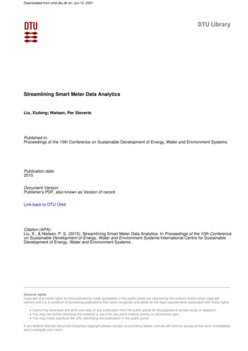
QRP-40 10
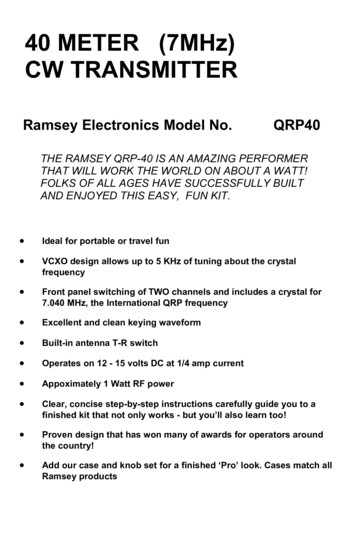
QRP40 PARTS LAYOUT DIAGRAM:QRP-40 11
"LEARN-AS-YOU-BUILD" TRANSMITTER ASSEMBLY STRATEGY:As you can see in examining the circuit board and components, there is a bitmore to this transmitter kit than soldering a few parts and putting a signal on theair. So that you don't spend extra time "troubleshooting" instead of getting onthe air, we strongly recommend you follow the assembly strategy and step-bystep procedures we are providing.Our strategy in installing parts on our PC board is to install the larger and moreobvious parts such as the connectors and controls. These parts will then act as"landmarks" so that each additional device installed is seen in relationship tothem, or to others previously installed.In addition, we'll discuss the purpose of most of the components or groups ofcomponents as we go along. If you are new to the idea of building your owntransmitter, perhaps our explanations will help you understand and learn as wego along. The assembly sequence will follow the circuit flow from key jack toantenna as faithfully as is practical, as part of Ramsey's "Learn-As-You-Build"kit assembly philosophy.However, we do assume that anyone ready to construct an amateur radiotransmitter has also developed some familiarity with general electronicspractices and language. Therefore, you can expect the following procedures tomove along with less of the hand-holding which we offer for our receivers andother kit projects in which the FCC has less interest!FIRST ASSEMBLY STEPS:To get started and to put some landmarks on the circuit board, we'll insert andinstall the 3 RCA "phono jacks", the DC power connector, the VCXO crystalselector switch, and the VXO frequency control. With these parts in place, therelative positioning of further components will become easier to recognize.Refer frequently to your parts layout diagram.The three RCA jacks, the DC power connector and crystal switch are all "pressin-'til-flush" in design. On all three of the RCA jacks, the three large tabs aresoldered to the ground plane of the circuit board, while the thin tab is for thecenter conductor. (Be sure these thin tabs make it into each of their respectivecircuit board holes!) The crystal switch has a bottom with six circuit board pinsand a top with six corresponding tabs for other kinds of solder connections.Press the pin side of the switch into place as far as it will go. Press J4 into itsposition as far as it will go. 1. Insert and solder J1 (antenna connector)2. Insert and solder J2 (receiver connector)3. Insert and solder J3 (key, keyer or computer interface)4. Insert and solder J4 (DC power 12 to 14 volts)QRP-40 12
5. Insert and solder R1, the 10K tuning potentiometer. 6. Insert and solder S1, pushbutton switch.Carefully select, insert and solder the following components in the order givenin the following steps. Check off each step as completed. 7. C16, 100 to 220 uf electrolytic. Electrolytic capacitors are polarized,which means there is a right and a wrong way to install them! Generally,the Negative ( - ) side is indicated on the capacitor, while the Positive ( )is shown on the PC board. Make sure that the capacitor is insertedcorrectly into the PC board with the ( ) lead into the ( ) hole and the (- )lead into the ( - ) hole. 8. R11, 100 ohm (brown-black-brown). 9. C19, .01 uf (marked .01 or 103 or 10 nf). 10. D2, 1N4148 diode. This diode is the small glass bead type. For correctpolarity, the dark band must face as shown on the parts layout diagram. 11. C10, .01 uf (marked .01 or 103 or 10 nf).The preceding parts comprise much of the circuitry which blocks RF from thereceiver during transmission and permits the antenna to be connected to thereceiver jack during "key-up" conditions. To further complete this section of thecircuit, we now install the first of three 100 uh RF chokes. They look likeresistors with brown-black-brown-silver (or gold) bands. 12. Install L5, 100 uh inductor (brown-black-brown-silver). 13. Install R12, 1K resistor (brown-black-red). 14. Install R13, 1K resistor (brown-black-red). 15. Using a scrap component lead wire, install Jumper JMP1. Jumperwires simply connect two PC board traces together, jumping over othertraces!Next study the orientation of Q4, the keying transistor. Be careful in identifyingQ4. Q4 is the only PNP device, and its part number or case style may varyslightly. If necessary, positively identify Q1, the 2N3904 oscillator transistor,and set it aside for later, since Q4 is similar or identical in style. Proceed withthe following steps, in order,
qrp-40 1 40 meter (7mhz) cw transmitter ramsey electronics model no. qrp40 the ramsey qrp-40 is an am


![Merlin@home Transmitter [RF] [symbol update] [RED comp .](/img/10/7bd6c35e-42f6-4c21-be52-037b05000831.jpg)