Transcription
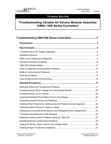
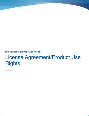
ProductDataVVT (Variable Volume andTemperature) Zoning System3V Control SystemThe VVT zoning system provides thefollowing features and benefits: New, easy-to-use System Pilotinterface Flexible architecture Simplified installation andcommissioningFeatures/BenefitsThe VVT zoning systemprovides an effective balancebetween flexible zone comfort,diverse system applicationrequirements, and efficienthigh-performance unitoperation.User interfaceThe VVT zoning system is designed toallow a service person or building owner to configure and operate the VVTbypass controller and zone controllers,linkage compatible air source and allother networked devices through theSystem Pilot user interface. The System Pilot’s backlit, alphanumeric Liquid Crystal Display (LCD) and rotaryknob design allow the user to navigatethrough the menus, select desired options and modify data with ease. AllVVT zoning system maintenance, configuration, setup and diagnostic information is available through the Level IIcommunications port to allow data access by the System Pilot or an attachedcomputer running Network ServiceTool or ComfortVIEWTM software.Flexibility for every applicationThe VVT zoning system maintains precise temperature control in the spaceby regulating the flow of conditionedCopyright 2004 Carrier CorporationForm 33ZC-1PD
air into the space using Carrier’sVVT Zone and Bypass Controllers.Buildings with diverse loading conditions can be supported by controllingreheat applications, including two-position hot water, modulating hot water,up to 3-stage electric heat or combination baseboard and ducted heat.Carrier’s VVT zoning system offerszone level flexibility with its expandedrange of compatible zone sensors.Now select the zone level of control required for every application. Carrier’ssensor offering includes simple spacetemperature sensors up to full networkcompatible devices. Carrier Linkage SystemcompatibilityWhen linked to a Carrier Linkage System, the VVT zoning system components provide numerous features andbenefits such as weighted average demand for system operation, referencezone temperature and set points, setpoint averaging, global set point schedule, and occupancy scheduling.Additional control featuresThe VVT zoning system componentsprovide additional control features suchas Occupied/Unoccupied schedulinginitialized via the network. The VVTzone controller offers override invokedfrom a wall sensor during unoccupiedhours from 1 to 1440 minutes in Ease of installation1-minute increments. Optional Demand Controlled Ventilation (DCV)The VVT zoning system componentscontrol or relative humidity monitoring are provided with removable connecare also available.tors for power, communications, anddamper output. Non-removable screwSimple actuator connectiontype connectors are used for inputs.The VVT zone controller control asThe VVT zone controller also providessembly contains an integral actuatoran RJ-14 modular phone jack for theassembly that is field mounted to theNetwork Service tool connection to theVVT terminal damper shaft, similar tomodule via the Carrier communicatingthe mounting of a standard actuator.network.The actuator is rated at 35 lb-in.Table of contentsFeatures/Benefits . . . . . . . . . . . . . . . . . . . . . . . . . . . . . . . . . . . . . . . . . . 1,2VVT System Key Components . . . . . . . . . . . . . . . . . . . . . . . . . . . . . . . . 3,4Dimensions . . . . . . . . . . . . . . . . . . . . . . . . . . . . . . . . . . . . . . . . . . . . . . 5-7Performance Data . . . . . . . . . . . . . . . . . . . . . . . . . . . . . . . . . . . . . . . . 8-10Application Data . . . . . . . . . . . . . . . . . . . . . . . . . . . . . . . . . . . . . . . . 11-14Guide Specifications — 3V Control System . . . . . . . . . . . . . . . . . . . . . 15-222(3.95 N-m) torque, a 45, 60, or90-degree stroke, and provides90-second nominal timing at 60 Hz.The actuator is suitable for mountingonto a 3/8-in. (9.5 mm) square orround VVT box damper shaft, or ontoa 1/2-in. (13 mm) round damper shaft.The minimum VVT box damper shaftlength is 13/4-in. (45 mm). The VVTzone controller is designed for verticalor horizontal mounting.105
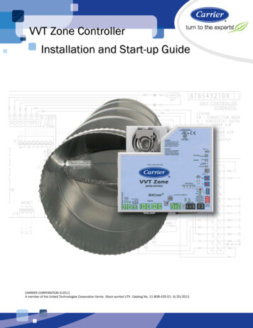
VVT system key componentsTerminal controlBypass controller (33ZCBC-01) — The VVT bypasscontroller is a component of Carrier’s 3V control systemand is used to regulate the supply duct static pressure forVariable Volume and Temperature Applications. Thebypass Controller is an essential system component thatallows constant volume HVAC equipment to provide zonelevel temperature control.VVT zone controller (33ZCVVTZC-01) — The VVTZone Controller is a component of Carrier’s 3V controlsystem and is used to provide zone level temperature andair quality control for Variable Volume and TemperatureApplications. The VVT zone controller is a pressure dependent device that maintains space temperature by modulating the amount of supply airflow through its primarydamper. An integrated 35 in.-lb actuator is standard on allVVT zone controllers.VVT zone controllers are available factory mounted toCarrier’s round and rectangular dampers. Round dampersare available in 6, 8, 10, 12, 14, and 16-in. sizes. Rectangular dampers are available in 8x10, 8x14, 8x18, and8x24-in. sizes. All damper assemblies are equipped with anintegrated duct temperature sensor.Zone controllers are available for field retrofit applications.VAV zone controller (33ZCVAVTRM, 33ZCFANTRM) —Carrier’s 3V control system provides seamless integrationof pressure independent zones for use with VVT systems.Simply use Carrier’s family of VAV zone controllers(ComfortID ) to regulate the flow of conditioned air intothe space. The VAV zone controllers provide dedicatedcontrol functions for single duct terminals with modulatingheat (up to 2-stages of heat), series fan or parallel fan powered terminals, or as a primary controller for dual duct orzone pressurization applications. Refer to Carrier’s ComfortID literature for additional information.Linkage compatible unit controls and auxiliarycontrolsCarrier’s 3V control system provides optimized equipmentcontrol through airside linkage. Linkage allows the airsource to adjust its supply air temperature set points andoccupancy schedules to run in the most efficient manner.The 3V control system linkage compatible controllersinclude ComfortLink , PremierLink and the UniversalController.ComfortLink controls — The factory-integrated controls are available on Carrier’s 2 to 25 ton Centurionrooftop product line. The ComfortLink controller is acomponent of Carrier’s 3V system and provides: optimumperformance of the rooftop’s refrigeration circuits, aneasy to read English scrolling marquee display and userinterface, and unparalleled diagnostic information withfactory-mounted sensors. PremierLink control (33CSPREMLK) — ThePremierLink communicating controller is available as a factory-installed option on 3 to 25 ton rooftop units and as afield-installed accessory. The control is DCV (DemandControlled Ventilation) compatible and internet ready.3Universal controller (33UNIVCTRL-01) — The Universal Controller provides auxiliary building control tointerface with lighting, fans, pumps and other HVACequipment in a stand-alone or Carrier-networked environment using closed-loop, direct digital controls. The Universal Controller’s pre-engineered algorithms provide simplebuilding integration for small-to-medium commercialapplications with 16 field point capability (8 inputs and8 outputs). Interface devicesSystem Pilot (33PILOT-01) — The System Pilot is acomponent of Carrier’s 3V control system and serves asthe user-interface and configuration tool for all Carriercommunicating devices. The System Pilot can be used toinstall and commission a 3V zoning system, linkage compatible air source, universal controller and all other devicesoperating on the Carrier communicating network.ComfortVIEW software (CEPL130548-01) —ComfortVIEW software can be installed on a PC and isused to configure and monitor the 3V -01) — The remote monitoring deviceinstalls on the Carrier network and provides a connectionfor a phone line or ethernet connection, allowing the userto view and change information using a standard webbrowser. The user will also have access to the point displays, set point schedules, and operating schedules.Field-installed accessoriesOption board (33ZCOPTBRD-01) — Carrier’s optional relay board may be used with VVT zone controllers toprovide control functions for heat and fan air terminals.Heating capabilities include modulating heat, up to 3 stages of ducted heat or combination baseboard and ductedheat control.Mounting kit — Mounting kits are used to field install theVVT zone controllers onto Carrier 33CS dampers. Mounting kits come in packages of 10. The 33ZCMBRC-01 kit isused when mounting on rectangular dampers. The33ZCMBRD-01 kit is used when mounting on rounddampers.SensorsOutdoor-air sensor (HH79NZ039) — The outdoor-airsensor reads temperatures between 0 and 150 F and isused to report the outdoor-air temperature to the communication bus. The information can be used to lock out heating or cooling modes when the temperature is not withinuser-configured limits. The outdoor-air sensor is neededwhen an economizer is used.Supply air temperature sensor (33ZCSENSAT) —The supply air temperature sensor is required for heatingapplications or stand-alone operation. The sensor has anoperating range of –40 to 245 F (–40 to 118 C) and includes a 6-in. stainless steel probe and cable. Duct temperature sensor (33ZCSENDAT) — Theduct temperature sensor is required for use with a bypasscontroller and must be installed in the supply air duct.105
VVT system key components (cont)For bypass systems, the duct temperature sensor shouldbe moved to a location which will provide the best sensingof the supply-air temperature during heating and cooling.For bypass systems, the duct temperature sensor shouldbe located in the main supply duct downstream of the discharge of the air source and before the bypass damper toallow good mixing of the supply airstream.Primary air temperature sensor — The primary airtemperature (PAT) sensor (part number 33ZCSENPAT) isused on a zone controller which is functioning as a LinkageCoordinator for a non-communicating or Linkage compatible air source.Space temperature sensor — A space temperature(SPT) sensor must be installed for each zone controller.There are 3 types of SPT sensors available from Carrier:the 33ZCT55SPT space temperature sensor withtimed override button, the 33ZCT56SPT space temperature sensor with timed override button and set point adjustment, and the 33ZCT59SPT space temperature sensorwith timed push button override button, set point adjustment and digital readout display.4The space temperature sensor is used to measure thebuilding interior temperature and should be located on aninterior building wall. Demand Controlled Ventilation sensor (CO2) — Anindoor air quality sensor is required for optionalDemand Controlled Ventilation. The 33ZCT55CO2 and33ZCT56CO2 CO2 sensors are indoor, wall-mounted sensors without display.NOTE: The relative humidity sensor and CO2 sensor cannot be used on the same zone controller.Humidity sensors — The relative humidity sensor is required for zone humidity control (dehumidification) forpressure independent zones only. The indoor wallmounted relative humidity sensor (33ZCSENSRH-01) orduct mounted relative humidity sensor (33ZCSENDRH-01)can be used.NOTE: The relative humidity sensor and CO2 sensor cannot be used on the same zone controller.105
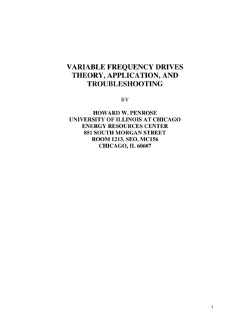
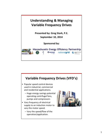
Dimensions BYPASS CONTROLLER VVT ZONE CONTROLLER(PRESSURE DEPENDENT)1055
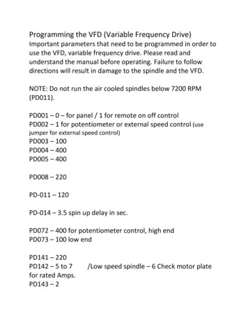
Dimensions (cont) SYSTEM PILOT6-in.(152 mm)3 1/2-in.(89 mm) 6PREMIERLINK COMMUNICATING CONTROLLER105
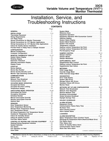
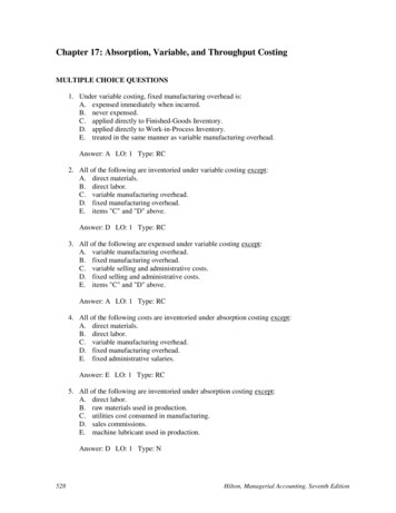
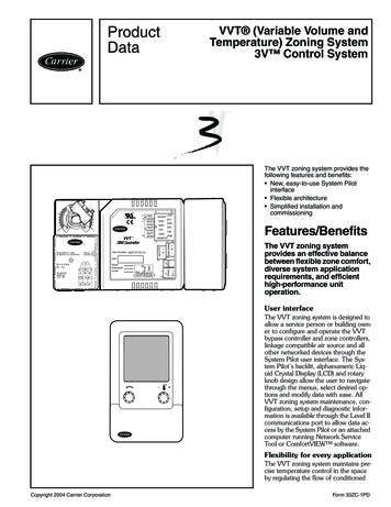
RECTANGULAR DAMPERS WITH VVT ZONE CONTROLLERADIMENSIONS D1808ZC-0133ZCD2408ZC-01BDE 24131/2131/2131/2131/24171/4PARTNUMBERDUCT CD1808ZC-0133ZCD2408ZC-018 x 108 x 148 x 188 x 2410.011.513.016.0CFM AIRFLOW RANGEMinMax41061056082572510759251175ROUND DAMPERS WITH VVT ZONE CONTROLLERDIMENSIONS (in.)6810121416WEIGHT(lb)7.09.010.514.016.017.5CFM AIRFLOW 7
Performance data APPLICATION NC* LEVELS (RADIATED SOUND) — ROUND ZONE 77033ZCDR12ZC-018609501425STATIC PRESSURE(in. .501.000.050.501.000.110.501.00NC LEVELExceeds recommended NC.*Noise Criteria.NOTE: The NC values are based on ARI (Air Conditioning and Refrigeration Institute) Standard 885-90 application assumptions.8105 20 2025 202224 202428283235 20 2022 3538223738223839273940324040404445
APPLICATION NC* LEVELS (RADIATED SOUND) — ROUND ZONE DAMPERS C PRESSURE(in. 30.501.000.180.501.00NC 941314042354144354245364446384546505154Exceeds recommended NC.*Noise Criteria.NOTE: The NC values are based on ARI (Air Conditioning and Refrigeration Institute) Standard 885-90 application assumptions.1059 pa
bypass Controller is an essential system component that allows constant volume HVAC equipment to provide zone level temperature control. VVT zone controller (33ZCVVTZC-01) — The VVT Zone Controller is a component of Carrier’s 3V control system and is used to provide zone level temperature and air quality control for Variable Volume and Temperature