Transcription
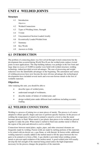
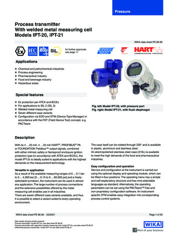
PressureProcess transmitterWith welded metal measuring cellModels IPT-20, IPT-21WIKA data sheet PE 86.06SILIEC 61508 / IEC 61511for further approvalssee page 11Applications Chemical and petrochemical industries Process engineering Pharmaceutical industry Food and beverage industry Hazardous areasSpecial features Ex protection per ATEX and IECEx For applications to SIL 2 (SIL 3) Welded metal measuring cell Seven different case variantsFig. left: Model IPT-20, with pressure portFig. right: Model IPT-21, with flush diaphragm Configuration via EDD and DTM (Device Type Manager) inaccordance with the FDT (Field Device Tool) concept, e.g.PACTwareDescriptionWith its 4 . 20 mA, 4 . 20 mA HART , PROFIBUS PAor FOUNDATION Fieldbus output signals, combinedwith either intrinsic safety or flameproof enclosure ignitionprotection type (in accordance with ATEX and IECEx), themodel IPT-2x is ideally suited to applications with the highestdemands on the measurement technology.Versatile in applicationAs a result of the available measuring ranges of 0 . 0.1 barto 0 . 4,000 bar [0 . 0.15 to 0 . 60,000 psi] and a freelyselectable turndown, the instrument can be used in almostany application. The large number of process connectionsand the extensive possibilities offered by the metalmeasuring cell enables use in all industries.There are seven different case variants available, and thusit is possible to select a variant suited to every operatingenvironment.The case itself can be rotated through 330 and is availablein plastic, aluminium and stainless steel.An electropolished stainless steel case (316L) is availableto meet the high demands of the food and pharmaceuticalindustries.Easy configuration and operationService and configuration at the instrument is carried outusing the optional display and operating module, which canbe fitted in four positions. The operating menu has a simpleand self-explanatory structure and has nine selectablelanguages as standard. Alternatively, the operatingparameters can be set using the PACTware free andnon-proprietary configuration software. An instrumentspecific DTM enables easy integration into correspondingprocess control systems.WIKA data sheet PE 86.06 03/2021Data sheets showing similar products:Process transmitter; model UPT-2x, see data sheet PE 86.05Process transmitter with capacitive ceramic measuring cell; model CPT-2x, see data sheet PE 86.07Differential pressure transmitter; model DPT-10; see data sheet PE 86.21Page 1 of 20
SpecificationsInstrument versions and measuring cellsVersionMeasuring cellVersion with cooling element(extended medium temperature range)Metal measuring cell with piezoresistive sensor or thin-film sensor (depending on measuringrange)Metal measuring cell with piezoresistive sensor or thin-film sensor (depending on measuringrange)Standard versionHigh-temperature versionCeramic/metal measuring cell ( for medium temperatures up to 200 C [392 F], see operatingconditions)Measuring rangesGauge pressurebarpsi0 . 0.1 2)0 . 0.40 . 10 . 2.50 . 50 . 100 . 250 . 400 . 1000 . 2500 . 6000 . 1,000 1)0 . 1,600 1)0 . 2,500 1)0 . 4,000 1)0 . 50 . 150 . 300 . 750 . 1.50 . 1500 . 3000 . 5000 . 1,4500 . 3,0000 . 9,0000 . 15,000 1)0 . 30,000 1)0 . 50,000 1)0 . 60,000 1)0 . 0.4 2)0 . 12)Absolute pressurebarpsi0 . 0.1 2)0 . 50 . 100 . 250 . 400 . 1.50 . 50 . 150 . 300 . 1500 . 3000 . 500-0.05 . 0.05 2)-0.2 . 0.2-0.5 . 0.5-1 . 0-1 . 1.5-1 . 5-1 . 10-1 . 25Vacuum and /- measuring rangebar0 . 2.5-1 . 40psi-0.7 . 0.7-3 . 3-7 . 7-14.5 . 0-14.5 . 20-14.5 . 75-14.5 . 150-14.5 . 300-14.5 . 5001) Only for model IPT-202) Only for high-temperature versionOther measuring ranges can be set via turndown (scaling).Maximum setting range of the pressure value: -20 . 120 %For example, a 0 . 10 bar [0 . 150 psi] instrument can also be used from -1 . 10 bar [-14.5 . 150 psi].Values of less than 0 bar abs. [0 psia] cannot be set or measured.Vacuum/overload safetyVacuum safetyYes (not for oxygen applications)Overload safety (standard version, version with cooling element)Measuring range 40 bar [500 psi]3 timesMeasuring range 40 . 1,000 bar [500 . 15,000 psi]2 timesWIKA data sheet PE 86.06 03/2021Page 2 of 20
Vacuum/overload safetyMeasuring range 1,600 bar [30,000 psi]1.5 timesMeasuring range 2,500 bar [50,000 psi]1.4 timesMeasuring range 4,000 bar [60,000 psi]1.25 timesOverload safety (high-temperature version)Measuring range 0.1 bar [1.5 psi]15 bar [220 psi]Measuring range 0.4 bar [5 psi]30 bar [430 psi]Measuring range 1.0 bar [15 psi]35 bar [510 psi]Measuring ranges from 2.5 . 25 bar [30 . 300 psi]50 bar [720 psi]Output signalsOutput signals4 . 20 mA4 . 20 mA with a superimposed HART communication signal (option: SIL qualification)HART specification: 7.3FOUNDATION FieldbusPROFIBUS PASlave electronics for electrical differential pressure (option: SIL qualification)Signal types Load in Ω(UB - UBmin) / 0.022 AUB Applied supply voltage ( see table “Supply voltage”)UBmin Minimum supply voltage ( see table “Supply voltage”)Dampening0 . 999 s, adjustableAfter the set dampening time the instrument outputs 63 % of the applied pressure as output signal.Example: A pressure impulse increases from 0 to 10 bar with a dampening of 2 seconds. After the 2 seconds apressure of 6.3 bar is displayed.Step response time 80 ms ( dead time 25 ms rise time 10 . 90 % 55 ms)Accuracy specificationsAccuracy specificationsAccuracy at room temperature 1)Measuring range 1,000 bar [15,000 psi]0.1 % of span (options: 0.075 % / 0.2 %)Measuring range 1,000 bar [15,000 psi]0.5 % of spanAdjustabilityZero point-20 . 95 % (downwards, the adjustability is always limited by the minimum pressure of0 bar abs.)SpanMeasuring range 1,000 bar [15,000 psi]-120 . 120 % with a difference betweenzero point and span of max. 120 % of thenominal measuring rangeMeasuring range 1,000 bar [15,000 psi](0 bar abs.) . 105 % (downwards,the adjustability is always limited by theminimum pressure of 0 bar abs.)TurndownNon-linearity per BFSL (per IEC 61298-2)UnlimitedMeasuring range 1,000 bar [15,000 psi]Maximum recommended turndown 20:1Measuring range 1,000 bar [15,000 psi]Maximum recommended turndown 2:1SIL applicationsMax. turndown 10:1Measuring range 1,000 bar [15,000 psi] 0.05 % of spanMeasuring range 1,000 bar [15,000 psi] 0.25 % of spanWIKA data sheet PE 86.06 03/2021Page 3 of 20
Accuracy specificationsNon-repeatability (per IEC 61298-2)Measuring range 1,000 bar [15,000 psi] 0.1 % of spanMeasuring range 1,000 bar [15,000 psi] 0.5 % of spanBehaviour with turndown1:1 . 5:1 with measuring range 0.1 . 1,000bar [1.5 . 15,000 psi]No change in accuracy 5:1 with measuring range 0.1 .1,000 bar[1.5 . 15,000 psi](basic accuracy / 5) x turndown1:1 . 2:1 with measuring range 1,000 bar[15,000 psi] 0.5 % x turndownLong-term stability at reference conditions (standard version, version with cooling element)Measuring range 1 bar [15 psi] (0.35 % x turndown) / yearMeasuring range 1 bar [15 psi] (0.15 % x turndown) / yearMeasuring range 1 bar [15 psi] (0.10 % x turndown) / yearMeasuring range 1,000 bar [15,000 psi] (0.50 % x turndown) / yearLong-term stability at reference conditions(high-temperature version) (0.05 % x turndown) / yearThermal change, zero point and span (reference temperature 20 C [68 F])In compensated range10 . 70 C [50 . 158 F]Measuring range 1,000 bar [15,000 psi] 0.075 % / 10 K (max. 0.15 %)Measuring range 1,000 bar [15,000 psi]No compensated rangeOutside compensated rangeMeasuring range 1,000 bar [15,000 psi] 0.15 % 0.075 % / 10 KMeasuring range 1,000 bar [15,000 psi] 0.5 % 0.2 % / 10 KThermal change of the current output(reference temperature 20 C [68 F])Deviations through strong electromagneticfields within the scope of EN 61326-1 0.05 % / 10 K (max. 0.15 %) for 4 . 20 mA output at -40 . 80 C [-40 . 176 F] 150 μA1) Including non-linearity, hysteresis, zero offset and end value deviation (corresponds to measured error per IEC 61298-2). Calibrated in vertical mounting position with processconnection facing downwards.For use in hydrogen applications, observe the Technical information IN 00.40 at www.wika.com regarding long-term stability.Reference conditions (per IEC 61298-1)Reference conditions (per IEC 61298-1)Temperature18 . 30 C [64 . 86 F]Atmospheric pressure860 . 1,060 mbar [86 . 106 kPa, 12.5 . 15.4 psig]Air humidity45 . 75 % r. h.Curve characteristicsLinearCharacteristic curvedeterminationReference mounting positionTerminal method per IEC 61298-2Vertical, diaphragm points downwardWIKA data sheet PE 86.06 03/2021Page 4 of 20
Voltage supplySupply voltage (non-Ex and Ex d)Signal typeBacklighting4 . 20 mADC 9.6 . 35 VInactiveActive4 . 20 mA with a superimposed HART communication signalDC 9.6 . 35 VDC 16 . 35 VDC 9 . 32 VDC 13.5 . 32 VPROFIBUS PADC 9 . 32 VDC 13.5 . 32 V FOUNDATION Fieldbus DC 16 . 35 VSupply voltage (Ex ia)Signal typeBacklighting4 . 20 mADC 9.6 . 30 VInactiveActiveDC 16 . 30 VDC 9.6 . 30 VDC 16 . 30 VFOUNDATION FieldbusDC 9 . 24 V(DC 9 . 17.5 V Fisco)DC 13.5 . 24 V(DC 13.5 . 17.5 V Fisco)PROFIBUS PADC 9 . 24 V(DC 9 . 17.5 V Fisco)DC 13.5 . 24 V(DC 13.5 . 17.5 V Fisco)4 . 20 mA with a superimposed HART communication signal Process connectionsStandard process connections for model IPT-20EN 837 G½B M20 x 1.5 G ¼ B female, G ½ B male (for high-temperature version with metal/ceramic measuring cell)ANSI / ASME B1.20.1 ½ NPT ½ NPT female ¼ NPT female, ½ NPT maleStandard high-pressure connections for model IPT-20 from 1,600 bar [30,000 psi]- M16 x 1.5 femaleM20 x 1.5 female9/16-18 UNF female1 1/8 -12 UNF female threadAseptic process connections for model IPT-21G½BG1BG1½BG 1 hygienicFlush ANSI / ASME B1.20.1½ NPT (for high-temperature version)- M44 x 1.25 with union nut (for version with cooling element) M44 x 1.25 with union nut (for high-temperature version)TRI-CLAMP 1 ½" 2"VARINLINE Form F Form NGrooved union nut DIN 11851 DN 25 DN 40 DN 50WIKA data sheet PE 86.06 03/2021Page 5 of 20
Aseptic process connections for model IPT-21NEUMO BioControl Size 50 Size 65Clamp connection per DIN 11864-3 DN 40 DN 50BioControl is a registered trademark of NEUMO.Pressure transmission mediumStandard version and extended medium temperature rangeModel IPT-20Model IPT-21Measuring range 40 bar [500 psi]Synthetic oil, halocarbon oilMeasuring range 40 bar [500 psi]Dry measuring cellSynthetic oil, halocarbon oilHigh-temperature versionModels IPT-20 and IPT-21Medicinal white mineral oilHalocarbon oil, generally with oxygen applications, not with vacuum and absolute pressure 1 bar abs. The applicationdemands special cleaning processes which ensure oil and grease-free surfaces.Optionally FDA-listed media for the food industry are available. All media are silicone-free.Diaphragm sealBy using diaphragm seals, it is possible to adapt the process transmitter to even the mostdifficult of conditions in the process industry. Thus, the transmitter can be used at extremetemperatures, and with aggressive, corrosive, heterogeneous, abrasive, highly viscous ortoxic media. As a result of the wide variety of aseptic connections (such as clamp, threadedpipe or DIN 11864 aseptic connections) measuring assemblies meet the high demands ofsterile process engineering.MaterialsMaterialsWetted partsStandard version, version withcooling elementModel IPT-20Measuring ranges 40 bar [500 psi]: Stainless steel 316L/1.4404Measuring ranges 40 bar [500 psi]: Stainless steel 316L/1.4404 Elgiloy 2.4711Measuring ranges 1,000 bar [15,000 psi]: Stainless steel XM-13/1.4534Model IPT-21High-temperature versionO-ring (only for model IPT-21)Model IPT-20,IPT-21StandardStainless steel 316L/1.4404OptionHastelloy C276/2.4819OptionGold-plated 20 µOptionGold/rhodium-plated 5 µ/1 µStainless steel 316L / Hastelloy HC276NBR, FKM, EPDM, FFKM, FEPM316L stainless steel, corresponds to 1.4404 or 1.4435316Ti stainless steel, corresponds to 1.4571CaseMaterialSingle chamber case, plasticPBT, polyesterSingle chamber case, cast stainless steelStainless steel 316LDouble chamber case, plasticPBT, polyesterSingle chamber case, aluminiumDie-casting AlSi10Mg, powder-coated on PE basisSingle chamber case, electropolished stainless steel, deep-drawnStainless steel 316LWIKA data sheet PE 86.06 03/2021Page 6 of 20
CaseMaterialDie-casting AlSi10Mg, powder-coated on PE basisDouble chamber case, aluminiumStainless steel 316LDouble chamber case, cast stainless steelElectrical connectionElectrical connectionWire cross-section:Wire or strand: 0.2 . 2.5 mm² (AWG 24 . 14)Strand with end splice: 0.2 . 1.5 mm² (AWG 24 . 16)Spring-loaded terminalsCable glands M20 x 1.5Plastic, PASealingNBRCable diameter 5 . 9 mm [0.2 . 0.35 in] 6 .12 mm [0.24 . 0.47 in] 10 . 14 mm [0.39 . 0.55 in]SealingNBRCable diameter9 . 13 mm [0.35 . 0.51 in] (for armoured cable)SealingNBRCable diameter7 . 12 mm [0.28 . 0.47 in]Plastic, PACable diameter5 . 9 mm [0.2 . 0.35 in]Brass, nickel-platedCable diameter6 . 12 mm [0.24 . 0.47 in]Cable diameter9 . 13 mm [0.35 . 0.51 in] (for armoured cable)Brass, nickel-platedStainless steelCable glands ½ NPTSealed with blind plugBrass, nickel-platedWire cross-section: max. 1.5 mm2 (AWG 16)Ingress protection: IP65 1)Angular connector DIN 175301803A with mating connectorIngress protection: IP65 1)Circular connector M12 x 1 (4-pin)without mating connectorReverse polarity protectionElectrical safety1) The stated ingress protection only applies when plugged in using mating connectors that have the appropriate ingress protection.Connection compartment for single chamber c
Vacuum safety Yes (not for oxygen applications) Overload safety (standard version, version with cooling element) . Turndown Unlimited Measuring range 1,000 bar [15,000 psi] Maximum recommended turndown 2:1 SIL applications Max. turndown 10:1 Non-linearity per BFSL (per IEC 61298-2) WIKA data sheet PE 86.06 03/2021 Page 4 of 20 Accuracy specifications Non-repeatability (per IEC 61298-2 .