Transcription
MCE Deepwater Development 2016A smart LNG Offloading to ConventionalLNG Carriers in Severe Open SeaEnvironmentsMarc CAHAYPAU, FRANCE 5‐7 APRIL 2016
MCE Deepwater Development 2016FLNG offloading state of the artExpected design features LNG loading of conventional/unmodified LNG carriers. High operability (up to at least Hs 4 m). Large separation between units providing protection against risk ofcollision & process upsets. Minimize LNG transfer lines length ( minimize pressure drop/BoG). Use of proven or qualified technologies.Current side‐by‐side and tandem offloading systemsdo not satisfy all wishes
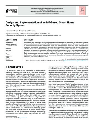
MCE Deepwater Development 2016FLNG offloading state of the artSide‐by‐sideMidship loadingTandemBow loadingHiLoad LNG TandemMidship loadingConventionalDedicatedConventional(no DP, midship manifold)(w/ or w/o DP, Bow Loading System)(w/o DP, midship manifold)Waves/OperabilityUp to Hs 2.5 mUp to Hs 5.5 mUp to Hs 4 mSeparation Distance(Collision & Process upset)Close vicinityLarge distanceLarge distanceLNG TransferLength/Efficiency 30 m 150 m 350 mLNG Transfer TechnologyMLAQualifiedAerial flexible pipeQualifiedFloating flexible pipeUnder qualificationLNGC FleetCan we Take LNG Offloading Further?
MCE Deepwater Development 2016HiLoad LNG Parallel Loading SystemA smart solution meetings all expectationsHiLoad LNG PLSMidship loadingLNGC FleetConventional(w/o DP, midship manifold)Waves/OperabilityAt least Hs 4 mSeparation distance(Collision & Process upset)Large distanceLNG TransferLength/Efficiency 100 mLNG Transfer TechnologyAerial flexible pipe& MLA Qualified
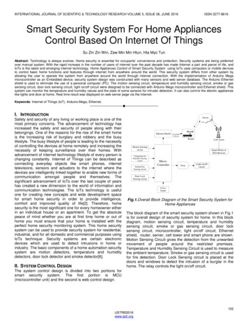
MCE Deepwater Development 2016HiLoad LNG Parallel Loading SystemDP Support VesselConstant 30-40 tons pullLNG Loading ArmsNo relative motionReelsDP2 Station Keeping ofLNG Carrier by HiLoad LNG150 tons bollard pull3 x 18” LNG Aerial FlexiblesFLNG w/ Heading ControlFLNG to “lock” the heading based on given environmental conditions.When environment direction is changing, FLNG heading to be adjustedaccording to Mooring Master instructionConventional LNG CarrierNo modification required
MCE Deepwater Development 2016FLNGOperational Envelope – LNGC Position KeepingGreenNormal LNG Transfer OperationDiameter: 20 mYellowESD 1: Stop LNG Transferand close valvesWidth: 2.5 mDP Set-pointDirection of resultant force(wind, wave and current)RedOperational Envelope for the DP Support Vessel(typical 30 m diameter)ESD2: Disconnect the LNGFlexibles and prepare to moveLNGC away from the FLNGWidth: 2.5 m
MCE Deepwater Development 2016FLNGOperational Envelope – LNGC Heading Control5oESD2 when Parallel to FLNGESD15oESD1Operational Envelope for the FLNG Support Vessel(typical 30 m diameter)
MCE Deepwater Development 2016Change of FLNG Heading107 m(FLNG)20o90o120 m(HiLoad)90 m(DP Support Vessel)
MCE Deepwater Development 2016LNG Fluid Transfer with Aerial FlexiblesSpare reelVapour Return1 x 18” LNG Aerial FlexibleLNG Flow2 x 18” LNG Aerial Flexibles
MCE Deepwater Development 2016Proven or qualified technologiesLNG transfer – Amplitude-LNG Loading System (ALLS)ShipmanifoldConnectionwinchConnectis GuidingdevicesLNG Flexible PipeQC/DCEmergencyRelease SystemConnection SystemConnectis Flexible pipe Gaz de France – Direction de la RechercheEmergency Release System based on two field proven high performance butterfly valves by KSB Amri,double offset disc, metal to metal seat, fire safe, long tightness life and strong autoclave characteristics.
MCE Deepwater Development 2016Proven or qualified technologiesDP station keeping by HiLoad DPStandard LNG Loading Armsconnected to LNGC Manifold.No relative motion. 4 x 2800 kW diesel engines(CAT C175/60, MTU 20V4000P83, or similar). 4 x 2300 kW azimuth thrusters (4 x 50%)Compact Azipod or mechanical thruster.3 x 16” Quick Connect/DisconnectCoupler for LNG/Vapour Flexibles.Note: Location not updated
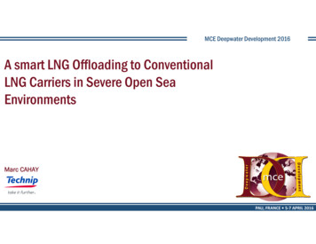
MCE Deepwater Development 2016Roll Damping by HiLoad keel Reduced Sloshing11.650%Roll Reduction5.6Typ. Roll center(HiLoad passive only)80% RollReduction0.096 HzT 10.4 sec(by active damping withHiLoad thrusters)0.071 HzT 14.0 secMain roll damping effect for waves withperiods in [ 8s ; 15s ]UP to 50% ROLL REDUCTION LNGC without HiLoad(by passive damping from HiLoad only) LNGC with HiLoad (passive) LNGC with HiLoad (constant thrust)UP to 80% ROLL REDUCTION LNGC with HiLoad (thrusters ‐ active) LNGC with HiLoad (thrusters ‐ active ‐ higher power)(by active damping from HiLoad thrusters)
MCE Deepwater Development 2016DEMO at MARIN Simulator – Sept 2015Bridge Simulator Set-upLNGC Bridge at MARIN SimulatorView from LNGC Bridge during LNG TransferView from LNGC Bridge during Approach to LNGC
MCE Deepwater Development 2016DEMO at MARIN Simulator – Sept 2015HiLoad Master at the Bridge of the HiLoad VesselMooring Master at LNGC Bridge during ApproachTug MasterTyp. LNGC Position Trace during Approach
MCE Deepwater Development 2016LNGC Heading Control by RudderDP station keeping by HiLoad DPHeading control by rudderLNGC Bow Thrusterin Back-up (if any)DP Station Keeping of LNG Carrierby HiLoad – Typ. 150 tons bollard pullFLNG w/ Heading ControlFLNG Heading “locked” based on direction of environmental forcesNo Support Vessel RequiredLNGC Main Engine inconstant “Dead Slow Ahead”Typ. forward force: 40-50 tonsHeading Controlby LNGC Rudderin Autopilot
MCE Deepwater Development 2016Active & Passive Safety BarriersCTechnip Generic FLNG: Loa 395.6 m, B 65.0 mEmergency Quick Release ofLNG Flexible Pipes within 8 secondsSafety barriers in case of emergency escape:EBEnvironmentResultant of Wind, Wave and CurrentADHiLoad LNG PLS is a Fail Safe solutionAHiLoad thrusters, 150 ton instant bollard pull in any directionBLNGC engineCFLNG AFT thrustersDLNGC bow thrusterEEnvironmental Forces
MCE Deepwater Development 2016ConclusionHiLoad LNG PLS Combines the advantages of Side by Side and TandemSAFETYEFFICIENCYFLEXIBILITYLarge separation distance: 100 mOperation in up to Hs 4.0 mNo personnel transfer via crew boatall travels safely to LNGC with HiLoadIncreased offloading operabilityEnables use of any conventionalLNGCRoll Reduction of LNGCDP2 Station Keeping of LNGC byHiLoadEven non-DP LNGCTug is not strictly required (efficientheading control with rudder)Any ConventionalLNG CarrierHs 4.0 m100 mDP2
MCE Deepwater Development 2016Thank you Contacts:Brian A. Robertsbaroberts@technip.comStéphane Paquetspaquet@technip.comMarc Cahaymcahay@technip.comSvein B. Hellesmarksbh@7Seas.no
LNG Loading Arms No relative motion Reels. MCE Deepwater Development 2016 Operational Envelope – LNGC Position Keeping DP Set-point Green Yellow Red Normal LNG Transfer Operation Diameter: 20 m ESD 1: Stop LNG Transfer and close valves Width: 2.5 m ESD2: Disconnect the LNG Flexibles and prepare to move LNGC away from the FLNG Width: 2.5 m FLNG Operational Envelope for the DP