Transcription
CFDCentreSchoolof somethingFacultyofOTHEREngineeringFACULTY OFAn optimization study of a ship hullANSYS Webinar 7,9 June 2011
Optimization of a ship hullImproving the performance of a ship hullHOW?Several configurations have to be testedClassical approach: towing tank tests money and time demandingCFD optimizationRequisites: reliable cheap fastCAD & mesh generationrequire many man-hoursANSYS Workbench ANSYS FLUENT RBF-MorphRBF-Morph
Test case descriptionShip hull: Series 60, CB 0.6 external hydrodynamics multiphase flow (air & water) ship advancing steadly in calm water trim and sinkage fixed displaced volume as constraint resistance predictionTARGET:Optimization of the hull shapewith no displacement reductionReduction of the resistance
WorkflowANSYS WorkbenchoperatorCADRBF-MorphMesh ICEM-CFDBaseline sim.FluentworkbenchWorkbench andRBF-morph setupDOE initionDesign sesurfaceCandidates(new design points)OptimizationOptimizationFinal solutionAutomated
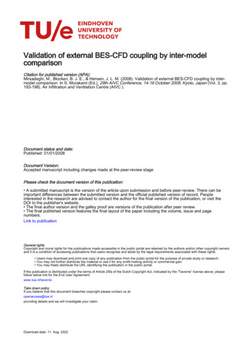
Baseline simulation,results Model length (Lpp) 3.048m; Fr 0.316 Steady-state simulations; VOF Structured grids (ICEM-CFD)Wave profile on the hullWave patternFLUENTExp.*Selected foroptimization*IIHR, University of -5.96x10⁻³-
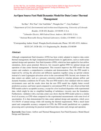
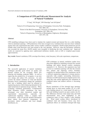
RBF-Morph setupCross sectionsEncapsulation domain to limitthe action of the morpher
RBF-Morph setupSymmetry planefixedMorphingdomainEight crosssectionsSectionsdeformationBase scale factor for each section: 1.1Multiplied by the amplification factor
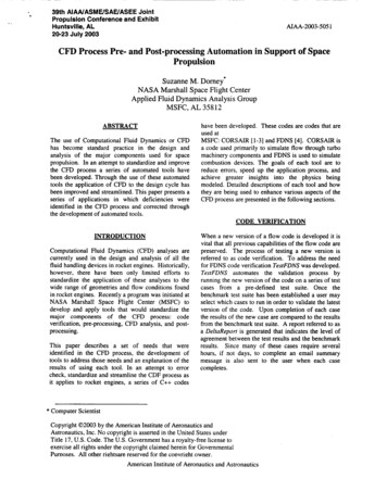
Morphing, sections
Morphing, effect on the mesh
RBF-Morph set-up,integration in the workbenchParameters definition(Fluent RBF Morph) 8 input parameters: amplification factors 2 output parameters: resistance and volume Amplification factors exported as parameters to the workbench Initial solution: baseline solution Automatic modification of the case file: morphing
Workbench set-up,Goal driven optimizationSensitivityDesign ofanalysisExperiments 45 design pointsInput parametersOutput parametersResponse surfaceCombinations ofdeformationsDOE settingsOptimization
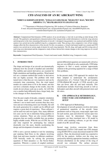
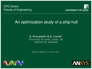
ne-7.9%resistance reductionNo volume reductionoptimizedoptimized
ConclusionsPerformance: Mesh generation: 6 man-hours Fluent case setup: 1 man-hours Baseline simulation (coarse grid): 4 CPU*-hours Workbench and RBF-Morph setup:1 man-hours DOE (45 simulations): 45 CPU*-hours 1 day man-time 2 days CPU-timeBenefits: integrated in the ANSYS software, automated no need to go back to CAD no need to remesh the model no loss of grid quality for small deformations few human hours necessaryWhat without Workbench & RBF-Morph. Mesh generation (first mesh): 6 man-hours Geometry (CAD) and mesh modification for each case(considering mesh automation in ICEM-CFD): 1x45 45 man-hours Cases management (Fluent): 1x46 46 man-hours Cases execution: 4 45 49 CPU*-hours use of other optimization tools: ?*one Intel i7 quad-core processor, 2.8GHz 100 man-hours 2 days CPU-time(optimistically.)
Next Steps more cross sections higher resolution trim and sinkage corrections 2 Degrees of Freedom Moving mesh
CFD Centre Faculty of Engineering An optimization study of a ship hull ANSYS Webinar 7,9 June 2011 . Optimization of a ship hull . Mesh ICEM-CFD Baseline sim. Fluent Workbench and RBF-morph setup DOE RUNS Optimization Final solution or Deformed RBF-Morph Design Of Experiments Parameters definition