Transcription
Al2O3 Precursor Evaluation for SALD JoiningC. M. Weiss, H.L. MarcusInstitute of Materials Science, Materials Science and Engineering Program/CMBE,University of Connecticut, StorrsAbstract:SFF technology is not limited to the creation of components and objects. Freeformtechnology can be a mechanism for joining of materials. By defining the space between twoobjects as the boundary for a free-form object it is possible to form a three dimensional joint fill.Selective Area Laser Deposition or SALD, has been used for free form and joining of carbidesand nitrides but has the potential to make other classes of ceramics. By selecting a metal-organicprecursor and an oxidizer, an oxide can be created by CVD gas decomposition. In this study suchoxide joint fill precursors are studied, particularly for alumina.Background:Gas phase laser chemical vapor deposition has been used for the formation of solidfreeform objects.[1,2] The technology for Selective Area laser deposition or SALD andSelective area laser deposition and vapor infiltration, SALDVI can be modified for the purposeof joint formation and crack repair. In order to do this the crack or open space of the joint isdefined as the inverse of a solid free form object and a computer scan path is generated for thelaser. This technique has been used for the formation of silicon carbide joints of tubes in theSALD mode.[3,4,5] Joining attempts were made for flat plate specimens using the SALDVImethod.[6] Silicon carbide and Silicon Nitride have been previously explored as the SALDjoint fill material but oxides have not. Joining of aluminum oxide using SALD or SALDVI hasnot previously been reported. Al2O3 deposited from the gas phase, is a material that is showingpotential as a possible joint fill material, and precursors are being evaluated for this type ofdeposition.In order to deposit alumina onto alumina or onto another substrate with the SALD, orSALDVI process, a precursor must be selected. When performing a SiC deposition it is possibleto utilize a precursor that, in one molecule, contains the Si and C needed to form the SiC.Tetramethylsilane (TMS) is such a precursor. Other ceramics will often require the use ofmultiple precursor chemicals. For instance, Si3N4 can be deposited with a combination of TMSand ammonia as a nitrogen source. In order to join alumina, a precursor must be selected thatcontains both oxygen and aluminum, or multiple precursors must be used. Besides thisconsideration, a viable precursor for the SALDVI process applied to joining should be one with arelatively high vapor pressure. This usually limits the selection candidates to a liquid or gas.For formation of alumina, several solid precursors exist and have been used in theformation of films but their use necessitates heating for vaporization. They are then primarilyused in flowing system hot or cold walled CVD reactors.[7] For deposition using an unheatedchamber with a fixed gas supply, this type of precursor is not suitable. Trimethylaluminum(TMA), (CH3)3Al was chosen as a source of aluminum because of its vapor pressure, 11 torr atroom temperature; it is a liquid at room temperature. TMA has been used in several studies as181
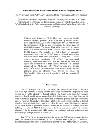
the Al source for alumina in certain types of chemical vapor deposition, particularly epitaxialmonolayer growth. Although this type of growth is not suitable for the SALDVI process, theexperiments indicate alumina is formed with this chemical precursor. The studies also indicateseveral oxidizer choices. Oxygen sources that have been used for Al2O3 growth include, N2O,NO2 H2O and H2O2.[8,9] Oxygen was not used in these studies because of the spontaneity of thereaction.TMA is pyrophoric alkyl and will react immediately with atmospheric oxygen if released.This necessitates special handling and experimental restrictions. In order to use this chemical fordeposition studies, the vapor is extracted into a vacuum and the liquid is never exposed toatmosphere or directly to any process oxygen. The TMA is used only below its roomtemperature vapor pressure to prevent condensation on the chamber walls as a liquid. N2O orH2O were chosen as the first precursor possibilities. N2O as it is a non-toxic gas that can beeasily introduced at any pressure. H2O was chosen because of its stoichiometric reactionpotential: 3(H2O) 2((CH3)3Al) Al2O3 6(CH4). Hydrogen is also added to this reactionthough it is not stoichiometricly necessary. Hydrogen in excess, it is believed, assists in theformation of the desired CH4 product instead of creating hydrocarbon contamination.[10]Experimental Setup:The experimental setup for the formation of Al2O3 joint is a modified version of theSALD system. A manifold of gasses, Argon, H2, N2O and O2 is attached to the system. TheTMA and water are each uniquely valved off from the main system . The TMA feeds into achamber that serves as a reservoir of vapor so that the TMA liquid does not contact the processgasses. There is a similar chamber for water vapor to prevent the TMA vapor from coming incontact with the liquid water. When introducing the precursors into the system it is desirable tointroduce them in the vapor form. The sample work stage is within a vacuum chamber with awindow for the introduction of the laser beam. The laser is moved externally by a computercontrolled X-Y stage. The laser used in this study is a 1070nm wavelength fiber laser that is CWup to 100 watts. The laser is operated with a 70% beam planar beam splitter as there isinstability below 10 watts. With the filter the laser is precisely controllable between 3 and 30watts. The laser power and stage motion are controlled with a custom National InstrumentsLabview Code. This code is capable of interpolating a three dimensional machine path, eitherdirectly imputed or from a CAD file. The experimental setup is shown in figure 1.182
Figure 1: Schematic of Deposition and Joining Setup. A) Fiber laser 1070nm B)X-Y Stage withoptical train C) Focusing Lens D) Reaction Chamber E) Gas Cylinders and Manifold F) VacuumPumps G) Liquid Precursor and Expansion Chamber H) Chemical Neutralizing BubblerThe experimental procedure for the determination of viable precursors is as follows. Thereaction chamber and expansion chambers are flushed with argon and evacuated multiple timesand a 50 mtorr or lower vacuum is established. The reaction chamber and one expansionchamber are filled with TMA vapor and then evacuated to one torr below vapor pressure, vaporpressure being approximately 11 Torr. If water is to be used as the oxidizer the secondexpansion chamber is filled with water vapor. The partial pressures within the expansionchambers are regulated to achieve the correct ratios upon mixing. Expansion chambers are usedso that no liquid, H2O, H2O2, or TMA, can come in contact with a gas with which it might react.The liquids are thus mixed only in the gas phase. Once these precursors are mixed in the gasphase, additional process gasses are added. The gasses, which may be introduced into, thecurrent set up include: hydrogen, argon, nitrous oxide, oxygen, and ammonia. Each gas isintroduced through a manifold that has been evacuated so that each gas quantity is controlled.The purpose of these studies is to ascertain an oxidizer and aluminum source that can beused for pyrolytic laser CVD. A deposition is desired that will match the substrate composition,achieve a high degree of density, and show good adhesive properties to the substrate. Oxygen isnot listed as a potential precursor to be used with TMA, since it reacts spontaneously. In order totest oxygen as a potential precursor, two torr O2 was introduced into a chamber with TMA atvapor pressure. Low oxygen partial pressure was tested for the purpose of finding a lower limitbelow which, a spontaneous reaction would be prevented or slowed to a negligible pace. Even atthis low partial pressure the O2 rapidly reacted without any heat input from the laser. Below 2torr the theoretical yield of Al2O3 would be to low. A fine alumina powder, which stayedsuspended in the air for several minutes, was created by this reaction as well as potentially otherbyproducts. Studies indicate the reaction: [(CH3)3Al]2 O2 2(CH3)2AlOCH3 [11] may occur.Results:Water vapor and N2O have both been used as oxidizer sources with TMA. Water vaporand TMA will react to form amorphous Alumina, tested by EDS and X-ray diffraction, if thereaction occurs as a liquid based reaction. This was tested by using an over pressure of H2O andTMA, achieved by heating both liquids so that their vapor pressures would be doubled andallowing this super saturation to mix as a gas. The resulting reaction occurred both within thegas phase and on the surface of the reaction chamber, depositing Al2O3 on all cold surfaces andconstriction points. When the water and TMA were maintained 1 torr below their vaporpressures the spontaneous reaction either did not proceed or proceeded at a very slow rate.Nitrous oxide did not react spontaneously with the TMA at room temperature at anypartial pressure of N2O. Gas combinations of TMA, hydrogen and a single oxidizer source,either N2O or H2O did not yield a controlled deposition. By combining N2O and H2O withhydrogen, argon, and TMA, both SALD and SALDVI deposits were then possible.183
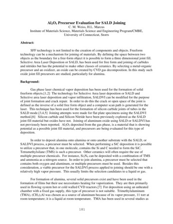
Using TMA as the aluminum source, and the combined oxidizer phase of H2O and N2O,alumina deposits were formed, both as a deposition into a powder bed and a deposition onto asubstrate both alumina. The SALDVI deposition occurred within an alumina powder bed. Thebed was created by repeated powder placement, agitation, and flattening by metal scraper. Thepowder surface was placed at the focal distance of the primary lens. A laser power of 15 watts,CW, was used to create a 3 mm square raster pattern with 50-micron spacing between rasterlines. The focused spot diameter at the powder surface was 100 micron. The laser scan speedwas 25 microns/s. The TMA and water vapor were used slightly below their vapor pressures.Argon, Hydrogen and N2O were all added at 150 torr. EDS performed on these deposits confirmsaluminum and oxygen ratios of matrix and powder regions of deposit that closely approximateAl2O3. X-ray diffraction indicates alumina. The resulting deposition is seen below in the ESEMmicrograph, Figure 2:Figure 2: 500x and 1000x ESEM micrographs of SALDVI deposition of alumina into an aluminapowder bed. Note the particles imbedded within the deposited matrix.The SALDVI deposit above appeared dense and was approximately the expected depositiongeometry. Metallographic examination is in progress.Deposition of the SALD type was also performed onto an alumina substrate. Theconditions for deposition were the same as above except the raster pattern defined a 1cm x 2 mmscan area and the laser passed each spot 6 passes as apposed to four of powder bed deposition. Adeposition was formed with a crisp interface as seen below in figure 3:184
Figure 3: SALD type deposition of alumina (right) on a sintered alumina substrate (left) at 470XmagnificationThe deposition was a distinctly different from the substrate but failed to achieve the desireddensity. The deposition did show very good adhesion to the substrate. X-ray diffraction patternsof the above substrate and deposition are shown below in figure 4 as well as an alumina pattern,which closely matches both l203 71-1684200010000010203040506070-10002 theta (deg)1858090100
Figure 4: X-ray diffraction patterns of substrate, deposition and corresponding pattern fromcard 71-1684 alumina.In an initial SALDVI joint attempt was performed that resulted in a deposition intopowder and adhesion to one work piece face. The deposition was composed of only two laserraster passes and consequently resulted in a non dense deposit. Seen below in figure 5 is adeposit on a joint wall.Figure 5: ESEM micrograph of SALDVI type deposit joint fill material. The light fluffy regioncomprises the deposited material and the larger crystalline shards are powder that has beeninfiltrated. The base substrate is not seen in this image.Summary:Alumina Deposits were successfully made by combining the precursors oftrimethylaluminum, nitrous oxide, hydrogen and water vapor. It was possible to use a computerdefined laser path to make a deposit of the same geometry. The deposits were well adhered tothe substrates. Shorter laser exposure time, resulting from fewer laser passes, resulted indeposits that were not dense. The density and adhesion increased with increasing laser dwelltime.As a precursor for the aluminum component, TMA has potential. A combination of H2Oand N2O serves as an oxygen source, however, the exact nature of the reaction is not known.There are difficulties in densification and localization of the reaction to the substrate or powdersurface; compositionally the alumina is as desired. As these conditions are improved, thenjoining will be possible with the SALDVI technique for alumina substrates. Work in the areaof joining is ongoing which is taking advantage of this precursor selection evaluation.186
References:[1] P. Calvert, R. Crockett, “Chemical Solid Free-Form Fabrication: Making Shapes withoutMolds,” Chem. Mater. 1997, 9, 650-663[2] J. E. Crocker, H. Wei, L. L. Shaw and H. L. Marcus, “SALDVI of SiC into metal andceramic powders,” Proceedings of the Solid Freeform Fabrication Symposium, The University ofTexas at Austin (2001), pp. 163–169[3] S. L. Harrison, “Selective Area Laser Deposition (SALD) Joining of Silicon Carbide withSilicon Carbide Filler,” PhD Dissertation, University of Connecticut, 1999[4] S.L. Harrison, H. L. Marcus, “Gas-phase Selective Area Laser Deposition SALD/ joiningof SiC,” Materials and Design 20 ,1999. pp 147-152[5] I. M. Ghayad, E. Geiss, J. E. Crocker and H. L. Marcus, “Spot joining of Si3N4 and SiCceramics using selective area laser deposition (SALD) technique,” Proceedings of the SolidFreeform Fabrication Symposium, The University of Texas at Austin (2001), pp. 170–174[6] C. M. Weiss, M. Aindow, H. Marcus, “Ceramic Joining by Gas Phase Pulsed LaserProcessing,” Solid Freeform Fabrication Proceedings, The Univeristy of Texas Austin, (2009)[7] H.O. Pierson, Handbook of Chemical Vapor Deposition, Elsevier, 1999[8] M.D. Groner, et al., “Low-Temperature Al2O3 Atomic Layer Deposition,” ChemicalMaterials, 16, 2004, pp. 639-645[9] D.N. Goldstein , et al., “Al2O3 Atomic Layer Deposition with Trimethylaluminum andOzone Studied by in Situ Transmission FTIR Spectroscopy and Quadrupole MassSpectrometry,” Journal of Physical Chemistry. 112, 2008, pp. 19530-19539[10] Figueras, S Garelik, J. Santiso, R. Rodroguez- Clemente, B. Armas, C. Combescure, A.Mazel, Y. Kihn, J. Sevely, “ Influence of H2 Partial Pressure on the Morphology andCrystallization of SiC Layers Obtained by LPCVD Using Tetramethylsilane,” Journal dePhysique IV Colloque C2 Supple. Au Journal de Physique II, September 1991 pp C2-225-232.[11] B. Ault, “ Matrix Isolation Investigation of the Reaction of (CH3)3Al with O2,” Journal ofOrganometallic Chemistry, 152, 1999, pp. 169-175187
TMA and water are each uniquely valved off from the main system . The TMA feeds into a chamber that serves as a reservoir of vapor so that the TMA liquid does not contact the process gasses. There is a similar chamber for water vapor to prevent the TMA vapor from coming in contact with the liquid water. When introducing the precursors into the .