Transcription
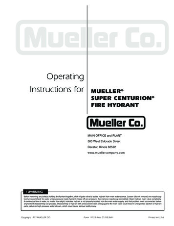
OperatingInstructions forMUELLER SUPER CENTURION FIRE HYDRANTMAIN OFFICE and PLANT500 West Eldorado StreetDecatur, Illinois 62522www.muellercompany.com! WARNINGBefore removing any bolts(s) holding the hydrant together, shut off gate valve to isolate hydrant from main water source. Loosen (do not remove) one nozzle captwo turns and check for water under pressure inside hydrant - bleed off any pressure, then remove nozzle cap completely. Open hydrant main valve completely.A continuous flow of water, no matter how slight, indicates hydrant is not properly isolated from the main water supply, and that problem must be corrected beforeany hydrant disassembly can proceed. Disassembly of hydrant with pressurized water acting against the main valve could result in unexpected ejection of hydrantparts, debris or high-pressure water stream, which could cause serious bodily injury.Copyright 1997-MUELLER CO.Form 11929- Rev. 02/09-3M-1Printed in U.S.A.
MUELLER SUPER CENTURION FIRE HYDRANTInspection and MaintenanceBeginning with the 1997 date codes, there are twostyles of Super Centurion Fire Hydrants:1) the Super Centurion 250 Hydrant and2) the Super Centurion 200 Hydrant.This manual applies to all Mueller Super Centurion FireHydrants with date codes 1997 or later. However, the250 psig rated 3-way Hydrant, which has O-ring Sealsat the Bonnet and Ground Line Flanges, is shown in allillustrations and O-rings are referred to in theinstructions. When working on a 2-way or 1-wayHydrant, which is rated at 200 psig, the foregoingreferences to O-rings should be understood to meanthe flat gaskets that are standard with 2-way and 1-wayHydrants.If water or oil overflowed from Oil Filler Hole, removeBonnet and replace O-rings in both the Bonnet andthe Hold Down Nut. Inspect and clean Stem, andreplace it if corroded or pitted. Check oil level. ReplaceBonnet and test for leaks.Use A-367 Brass Sleeve when removing or replacingBonnet or Hydrant Barrel to protect stem O-rings.Remove one Nozzle Cap, stand on the side of Hydrantopposite the cap removed, open Hydrant fully, andflush Barrel and Hydrant Lateral. Turn Operating Nutto fully CLOSED position.Remove all Nozzle Caps. Clean and lubricate threads.NOTE: HYDRANTS MADE PRIOR TO 1997 WILLCONTINUE TO USE FLAT GASKETS WHEN REPLACINGTHESE GASKETS AT THE BONNET AND SAFETYFLANGES.Examine inside of Barrel to make certain Drain Valveshave completely drained water from Barrel. If waterfails to drain from Barrel, it may be caused by one ormore of the following conditions:All Hydrants produced in 1997 and after have astainless steel Safety Coupling, Reversible Main Valve(patent pending) and two Shoe Bolts used to retainthe Drain Ring Housing.1. Water Table in ground is higher than drains.The 1997 style stainless steel Safety Coupling iscompatible with the Hydrants made prior to 1997.2. When Hydrant was installed, coarse gravel wasnot placed around Drains, in locations whereground has a make up such that it will notabsorb water.3. Drains are stopped by some foreign material.Non-reversible Main Valves for pre-1997 Hydrants areavailable. To retrofit such a Hydrant with the 1997 styleReversible Main Valve, both the Main Valve and theLower Valve Plate must be changed to the 1997 stylepart.For Hydrants made prior to 1997, see the operatinginstructions for the Centurion Fire Hydrant (Form10492).InspectionTo ensure their readiness for instantaneous use, it isrecommended that Fire Hydrants be inspected andtested at six-month intervals.4. Failure to leave Cap off of Hydrant to allow air toenter so Barrel will drain.The foregoing procedure introduces full line pressureto Drain Valves. It provides the best method forcleaning Drain Valves using water pressure.IMPORTANT - Initial installation of Hydrant MUST BEMADE PROPERLY so Safety Flange will functionproperly. Hydrant should be blocked at ground lineand around Shoe using concrete or similar substanceto prevent ground from giving way when Hydrant isstruck.Inspect visually for damaged or missing parts.Loosen one Nozzle Cap slightly and tighten the others.Open Hydrant fully. Tighten loose Nozzle Cap whenwater starts to flow. Remove Oil Filler Plug to check oillevel. If oil level is low, fill as shown on page 3. Checkall flange connections for leaks. Turn Operating Nut tofully CLOSED position.1For additional information on Hydrant anchorage,blocking, and drainage, see AWWA Standard C600and Manual M17.
MUELLER SUPER CENTURION FIRE HYDRANTPartsA-1Operating NutA-85 Weather SealA-3 Hold Down Nut O-ring - -16A-17Hold Down NutHold Down Nut O-ring - OutsideAnti-friction WasherOil PlugBonnetBonnet Bold and NutBonnet O-ringUpper StemStem O-ringNozzle LockPumper NozzlePumper Nozzle GasketPumper Nozzle O-ringPumper Nozzle 9A-30A-31A-32A-33A-34A-35A-36A-37A-38A-39A-40Hose NozzleHose Nozzle GasketHose Nozzle O-ringHose Nozzle CapChainChain Connector HookUpper Barrel (less nozzles)Safety CouplingSafety Flange Bolt and NutSafety Flange O-ringSafety FlangeCotter PinClevis PinLower StemLower BarrelStem PinDrain Valve FacingDrain Valve Facing ScrewUpper Valve PlateShoe bolt and nutDrain Ring Housing O-ringSeat Ring Top O-ringDrain Ring in RingSeat RingSeat Ring Bottom O-ringMain ValveLower Valve PlateCap Nut SealLock WasherLower Valve Plate NutShoeHydrant Lubrication Oil2
MUELLER SUPER CENTURION FIRE HYDRANTFilling Oil ReservoirCAUTION: Always fill the oil reservoir with the bonnet installed, the hydrant in its normal upright position, and themain valve fully closed. If the hydrant is filled with lubricant under any other circumstances, excess lubricate canoverfill the Bonnet and create a pressure lock. This could result in damage to the seals or Bonnet or prevent properhydrant operation.1. Remove Oil Filler Plug and check oillevel. Oil should be level with Oil FillerPlug Hole.32. If oil is low, use a small funnel to addMUELLER Hydrant Lubricant3. When oil is level with Oil Filler PlugHole, replace Oil Filler Plug.
MUELLER SUPER CENTURION FIRE HYDRANTFacing of Hose Nozzles1. Loosen Nuts on Safety Flange Bolts.3. Rotate Upper Barrel section asdesired.5. Tighten Safety Flange Bolts.6. Turn Operating Nut in closingdirection to make sure Main Valve isclosed tightly, then turn in openingdirection approximately 1/4 turn torelieve tension on operating mechanism.2. Turn Operating Nut slightly in theopening direction to relieve compressionbetween Barrel sections.4. Tighten Operating Nut, turning inclosing direction.4
MUELLER SUPER CENTURION FIRE HYDRANTReplacing Safety Stem Flange and Safety Stem Coupling1. Mueller Hydrant with Upper Barrelknocked over by truck. Note broken piecesof Safety Flange lying on ground.4. Assemble new Safety Stem Coupling toUpper Stem with new stainless steel ClevisPin and new stainless steel Cotter Pin. SafetyStem Coupling should be installed withnotches towards the Lower Stem.NOTE: “THIS END UP” STAMPED ONCOUPLING.2. Remove stainless steel Cotter Pin fromstainless steel Clevis Pin. Remove Clevis Pinand Safety Coupling from Upper Stem.Unbolt and remove broken Safety Flangefrom Upper Barrel. Remove Hold DownNut, Anti-Friction Washer, and OperatingNut from Bonnet. Lubricate Brass Sleeve andslide over threaded Stem end to prevent Oring damage. Unbolt Bonnet from UpperBarrel. Slide Upper Stem out of Bonnet andremove Brass Sleeve.3. Remove stainless steel Cotter Pin fromstainless steel Clevis Pin in Lower Stem (throwaway the old Clevis Pin and Cotter Pin).CAUTION: ALWAYS FILL THE OILRESERVOIR WITH THE BONNETINSTALLED, THE HYDRANT IN ITSNORMAL UPRIGHT POSITION, ANDTHE MAIN VALVE FULLY CLOSED. IFTHE HYDRANT IS FILLED WITHLUBRICANT UNDER ANY OTHERCIRCUMSTANCES, EXCESS LUBRICANTCAN OVERFILL THE BONNET ANDCREATE A PRESSURE LOCK. THISCOULD RESULT IN DAMAGE TO THESEALS OR BONNET, OR PREVENTPROPER HYDRANT OPERATION.57. Check Bonnet O-ring** for properposition and condition. Attach Brass Sleeveto Upper Stem and lubricate outside toprotect O-ring Seals from thread damage.Place Bonnet onto Upper Barrel andassemble Bonnet Bolts only hand-tight.Remove Brass Sleeve. Reassemble OperatingNut, Anti-Friction Washer, and Hold DownNut*. Be sure O-ring Seals are in goodcondition at thread shoulder on outside ofHold Down Nut and on in side wherecontact is made with Operating Nut.Remove Oil Filler Plug in side of Bonnet.Pour MUELLER Hydrant Lubricant into OilReservoir until it is level with the Oil FillerHole. Replace Oil Filler Plug.5. Assemble Upper Stem and new SafetyStem Coupling onto Lower Stem and retainit with the new stainless steel Clevis Pin andnew stainless steel Cotter Pin furnished withSafety Stem Coupling.6. Install O-ring** in groove in Ground LineFlange of Upper Barrel and place UpperBarrel carefully in position on Lower Barrel.Be sure that Upper Barrel is concentric withLower Barrel. Bolt the two halves of SafetyFlange into place (with bevel on outer edgedownward) and with Safety Flange snuglyfitting around Lower Barrel.8. Tighten Bonnet Bolts. Unscrew one HoseNozzle Cap slightly to bleed air. OpenHydrant fully. Tighten the Hose Nozzle Capwhen water starts flowing and check allflange connections for leaks. Turn OperatingNut to fully closed position and removeHose Nozzle Cap to allow Barrel to drain.Replace Hose Nozzle Cap.9. Turn Operating Nut in closing direction tomake sure Main Valve is closed tightly, thenturn in opening direction approximately 1/4turn to relieve tension on operatingmechanism.*TIGHTEN HOLD DOWN NUT TO 200-300 FTLBS OF TORQUE. IF TORQUE WRENCH IS NOTAVAILABLE, USE A 3 LB HAMMER TO STRIKETHE E ND OF THE A-311 WRENCH FIRMLYTWO TIMES TO ASSURE THE NUT IS PROPERLYTIGHTENED.**TO DETERMINE CORRE CT O-RINGS FORB O N NE T A N D G R O U N D L I NE F L A NG E S ,WHICH ARE SIMILAR IN APPEARANCE: SMALLERDI AME TER O-R IN G IS US E D AT B ON NE TFLANGE; LARGER AT GROUND LINE FLANGE.
MUELLER SUPER CENTURION FIRE HYDRANTRemoving Main Valve From Bonnet Flange! WARNINGBefore removing any bolt(s) holding the hydrant together, shut off gate valve to isolate hydrant from main water source.Loosen (do not remove) one nozzle cap two turns and check for water under pressure inside hydrant – bleed off any pressure,then remove nozzle cap completely. Open hydrant main valve completely. A continuous flow of water, no matter how slight,indicates hydrant is not properly isolated from the main water supply, and that problem must be corrected before anyhydrant disassembly can proceed. Disassembly of hydrant with pressurized water acting against the main valve could resultin unexpected ejection of hydrant parts, debris or high-pressure water stream, which could cause serious bodily injury.1. Remove Hold Down Nut, Operating Nut, andAnti-Friction Washer from Bonnet. LubricateBrass Sleeve and slide over threaded stem toprevent O-ring damage. Unbolt and removeBonnet. Remove Brass Sleeve.2. Slide slotted end of Wrench over top of Stemand engage the slot with Pin in Upper Stem.Thread Operating Nut onto stem and tightenagainst wrench to hold it securely. Lowersupport arm onto top flange of the Upper Barreland tighten Thumb Screw to hold the MainValve in the closed position. Shut off water at theGate Valve. Remove Main Valve Assembly byturning Seat Wrench counter-clockwise.4. Straighten stainless steel Lock Washer,unscrew Cap Nut and remove Washer, StemSeal, Lower Valve Plate, Main Valve and SeatRing. Clean, inspect and replace any damagedparts. (Main Valve can be reversed to providenew seal.) Replace Drain Ring Facings. Inspectand lubricate Top and Bottom Seat Ring O-rings(replace if necessary). Lubricate all threadedsurfaces and reassemble.5. With Cap Nut tightened to 100 ft-lbs on 51/4” Hydrant or 75 ft-lbs on 4 1/2” Hydrant,bend edges of stainless steel Lock Washer overone flat on the Lower Valve Plate and one flat onthe Cap Nut.8. Check Bonnet O-ring for proper position andcondition. Attach Brass Sleeve to Upper Stemand lubricate outside to protect O-ring Sealsfrom thread damage. Place Bonnet onto UpperBarrel and assemble Bonnet Bolts only handtight. Remove Brass Sleeve. ReassembleOperating Nut, Anti-Friction Washer, and HoldDown Nut*. Be sure O-ring Seals are in goodcondition at thread shoulder on outside of HoldDown Nut and on inside where contact is madewith Operating Nut. Remove Oil Filler Plug inside of Bonnet. Pour MUELLER HydrantLubricant into Oil Reservoir until it is level withthe Oil Filler Hole. Replace Oil Filler Plug.9. Tighten Bonnet Bolts. Unscrew one HoseNozzle Cap slightly to bleed air. Open hydrantfully. Tighten the Hose Nozzle Cap when waterstarts flowing and check all flange connectionsfor leaks. Turn Operating Nut to fully closedposition and remove Hose Nozzle Cap to allowBarrel to drain. Replace Nozzle Cap.3. Lift out Wrench, Lower Stem, Main Valve Assembly and Seat Ring from Hydrant Barrel as a unit.CAUTION: ALWAYS FILL THE OIL RESERVOIR WITH THE BONNET INSTALLED,THE HYDRANT IN ITS NORMAL UPRIGHTPOSITION, AND THE MAIN VALVE FULLYCLOSED. IF THE HYDRANT IS FILLEDWITH LUBRICANT UNDER ANY OTHERCIRCUMSTANCES, EXCESS LUBRICANTCAN OVERFILL THE BONNET ANDCREATE A PRESSURE LOCK. THIS COULDRESULT IN DAMAGE TO THE SEALS ORBONNET,ORPREVENTPROPERHYDRANT OPERATION.7. Turn Seat Wrench clockwise to tighten MainValve to 200 ft-lbs. Turn on water at the GateValve and remove Seat Wrench by removingoperating nut.6. Lower Main Valve, turn Seat Wrenchclockwise, and carefully thread Main Valve andSeat Ring into the base of the Hydrant handtight. Raise the Main Valve leaving about 1/2” ofplay between the Main Valve and Seat. LowerSupport Arm and tighten Thumb Screw.10. Turn Operating Nut in closing direction tomake sure Main Valve is closed tightly, then turnin opening direction approximately 1/4 turn torelieve tension on operating mechanism.*TIGHTEN HOLD DOWN NUT TO 200-300 FTLBS OF TORQUE. IF TORQUE WRE NCH IS NOTAVAILABLE, USE A 3 LB HAMME R TO STRIKE THEEND OF THE A-311 WRENCH FIRMLY TWOT I M E S T O A S S U R E T H E NU T I S P R O P E R L YTIGHTENED.6
MUELLER SUPER CENTURION FIRE HYDRANTRemove Main Valve from Lower Barrel Flange! WARNINGBefore removing any bolt(s) holding the hydrant together, shut off gate valve to isolate hydrant from main water source.Loosen (do not remove) one nozzle cap two turns and check for water under pressure inside hydrant – bleed off any pressure,then remove nozzle cap completely. Open hydrant main valve completely. A continuous flow of water, no matter how slight,indicates hydrant is not properly isolated from the main water supply, and that problem must be corrected before anyhydrant disassembly can proceed. Disassembly of hydrant with pressurized water acting against the main valve could resultin unexpected ejection of hydrant parts, debris or high-pressure water stream, which could cause serious bodily injury.1. Remove Hold Down Nut, Anti-Friction Washer,and Operating Nut from Bonnet. Lubricate BrassSleeve and slide over threaded stem end toprevent O-ring damage. Unbolt and removeBonnet. Remove Safety Flange Bolts and SafetyFlange. Remove Upper Barrel. Remove UpperStem and Stem Coupling from Lower Stem. Slideslotted end of Wrench over Lower Stem. Alignholes in Wrench and Stem and attach Wrench toStem with Clevis Pin. Lower Support Arm onto theFlange of Lower Barrel and tighten Thumb Screw(to hold Main Valve in closed position). Shut offwater at Gate Valve.4. Lower Main Valve Assembly and carefullythread Seat Ring into the base of the Hydranthand-tight. Raise the Main Valve leaving about1/2” of play between the Main Valve and Seat.Lower Support Arm onto Flange of LowerBarrel and tighten Thumb Screw.7. Check Bonnet O-ring** for proper positionand condition. Attach the Brass Sleeve to UpperStem and lubricate outside to protect O-ringSeals from thread damage. Place Bonnet ontoUpper Barrel and assemble Bonnet Bolts onlyhand-tight. Remove Brass Sleeve. ReassembleOperating Nut, Anti-Friction Washer, and HoldDown Nut*. Be sure O-ring Seals are in goodcondition at thread shoulder on outside of HoldDown Nut and on inside where contact is madewith Operating Nut. Remove Oil Filler Plug inside of Bonnet. Pour MUELLER HydrantLubricant into Oil Reservoir until it is level withOil Filler Plug Hole. Replace Oil Filler Plug.5. Tighten Main Valve to 200 ft-lbs. Turn onwater at the Gate Valve and remove Wrenchfrom Stem by removing Clevis Pin.2. Remove Main Valve Assembly by turningWrench counter-clockwise and lift out Wrench,Lower Stem, Main Valve Assembly and SeatRing from Hydrant Barrel as a unit.3. Straighten stainless steel Lock Washer,unscrew Cap Nut and remove Washer, StemSeal, Lower Valve Plate, Main Valve and SeatRing. Clean, inspect and replace any damagedparts. (Main Valve can be reversed to providenew seal.) Replace Drain Valve Facings. Inspectand lubricate Top and Bottom Seat Ring Orings (replace if necessary). Lubricate allthreaded surfaces and reassemble. With CapNut tightened to 100 ft-lbs on 5 1/4” Hydrant,or 75 ft-lbs on 4 1/2” Hydrant, bend edges onstainless steel Lock Washer over one flat on theLower Valve Plate and one flat on the Cap Nut.78. Tighten Bonnet Bolts. Unscrew one HoseNozzle Cap slightly to bleed air. Open Hydrantfully. Tighten the Hose Nozzle Cap when waterstarts flowing and check all flange connectionsfor leaks. Turn Operating Nut to fully closedposition and remove Hose Nozzle Cap to allowBarrel to drain. Replace Nozzle Cap.6. Reassemble Upper Stem to Lower Stem.Place Upper Barrel in place and reassembleSafety Flange.**CAUTION: Always fill the oil reservoirwith the bonnet installed, the hydrant inits normal upright position, and the mainvalve fully closed. If the hydrant is filledwith lubricant under any other circumstances, excess lubricant can overfill thebonnet and create a pressure lock. Thiscould result in damage to the seals orbonnet, or prevent proper hydrantoperation.9. Turn Operating Nut in closing direction tomake sure Main Valve is closed tightly, thenturn in opening direction approximately 1/4turn to relieve tension on operatingmechanism.*TIGHTEN HOLD DOWN NUT TO 200-300FT-LBS OF TORQUE. IF TORQUE WRENCH ISNOT AVAILABLE, USE A 3 LB HAMMER TOSTRIKE THE END OF THE A-311 WRENCHFIRMLY TWO TIMES TO ASSURE THE NUT ISPROPERLY TIGHTENED.**TO DETERMINE CORRECT O-RINGS FORBONNET AND GROUND LINE FLANGES,WHICH ARE SIMILAR IN APPEARANCE: SMALLERDIAMETER O-RING IS USED AT BONNETFLANGE; LARGER AT GROUND LINE FLANGE.
MUELLER SUPER CENTURION FIRE HYDRANTTo Replace Nozzles1. Remove Nozzle Cap.4. Remove Nozzle. The Nozzle Wrenchmay be struck with a heavy brasshammer or additional leverage may beobtained by placing a length of 2”schedule 40 steel pipe over the handleof the Nozzle Wrench.6. Remove Nozzle Cap and A-316Nozzle Wrench. Place the Nozzle Lock(Part 143137), lengthwise in the slotformed by either of the Nozzle DriveLugs and the Barrel Bore. Drive theNozzle Lock in place by striking theNozzle Lock Installation Tool (Part143132) several times with a heavybrass hammer.NOTE: Wear safety glasses whenusing a striking tool. The Nozzle Lockdoes not have to be completely seatedinto the slot, but it should be wellengaged along the entire length of theNozzle Drive Lug and Barrel Bore.2. Remove stainless steel Nozzle Lockby driving it out with a pointed tooland hammer.5. Thread new Nozzle into UpperBarrel, attach A-316 Nozzle Wrench asdescribed in Step 3, and tighten Nozzleto approximately 600 ft-lbs torque (100lbs. pull on a 6’ lever).7. Replace and tighten Nozzle Cap.3. Place Nozzle Wrench, A-316, onNozzle with Wrench Forks facingtoward Hydrant Barrel and locked ontoNozzle Drive Lugs. Replace Nozzle Capand tighten until Cap rests looselyagainst backside of Wrench.8
MUELLER SUPER CENTURION FIRE HYDRANTChanging Shoe1. Tighten Operating Nut to be sureMain Valve is in the fully closed position.4. Lubricate new Shoe and BottomSeat Ring O-ring.5. Position Shoe to slip in place.2. Remove all 6 Shoe Bolt Nuts.3. Slip off Hydrant Shoe.96. Slip new Shoe in place being carefulnot to damage Bottom Seat Ring O-ring.7. Replace Shoe Bolt Nuts. Tighten toapproximately 1800 in-lbs.
MUELLER SUPER CENTURION FIRE HYDRANTInserting Extension Section! WARNINGBefore removing any bolt(s) holding the hydrant together, shut off gate valve to isolate hydrant from main water source.Loosen (do not remove) one nozzle cap two turns and check for water under pressure inside hydrant – bleed off any pressure,then remove nozzle cap completely. Open hydrant main valve completely. A continuous flow of water, no matter how slight,indicates hydrant is not properly isolated from the main water supply, and that problem must be corrected before anyhydrant disassembly can proceed. Disassembly of hydrant with pressurized water acting against the main valve could resultin unexpected ejection of hydrant parts, debris or high-pressure water stream, which could cause serious bodily injury.1. Remove Hold Down Nut, Anti-FrictionWasher and Operating Nut from Bonnet.Lubricate outside of Brass Sleeve and slideover threaded stem end to prevent O-ringdamage. Unbolt Bonnet from Upper Barreland remove. Remove Brass Sleeve.2. Unbolt Safety Flange. Remove UpperBarrel. Remove Upper Stem and Safety StemCoupling by removing the lower stainlesssteel Cotter Pin and stainless steel Clevis Pin.4. Attach Extension Barrel to Lower Barrelwith solid Flange halves (without groove)and Bolts, being sure Flange Gasket is inplace.5. Assemble Upper Stem and Safety StemCoupling on to Extension Stem and retain itwith stainless steel Clevis Pin and stainlesssteel Cotter Pin. MAKE SURE SAFETY STEMCOUPLING IS INSTALLED WITH NOTCHESTOWARDS THE LOWER STEM. WORDS “THISEND UP” TOWARDS THE UPPER STEM.3. Place Extension Stem and ExtensionCoupling on Lower Stem and retain it withstainless steel Clevis Pin and stainless steelCotter Pin.CAUTION: Always fill the oil reservoirwith the bonnet installed, the hydrant inits normal upright position, and the mainvalve fully closed. If the hydrant is filledwith lubricant under any other circumstances, excess lubricant can overfill thebonnet and create a pressure lock. Thiscould result in damage to the seals orbonnet, or prevent proper hydrantoperation.6. Attach Upper Barrel with Safety FlangeHalves (with bevel on outer edgedownward) and Bolts; being sure SafetyFlange O-ring** is in groove in Upper Barrel.*TIGHTEN HOLD DOWN NUT TO 200-300FT-LBS OF TORQUE. IF TORQUE WRENCH ISNOT AVAILABLE, USE A 3 LB HAMMER TOSTRIKE THE END OF THE A-311 WRENCHFIRMLY TWO TIMES TO ASSURE THE NUT ISPROPERLY TIGHTENED.7. Check Bonnet O-ring** for proper positionand condition. Attach Brass Sleeve to UpperStem and lubricate outside to protect O-ringSeals from thread damage. Place Bonnetonto Upper Barrel and assemble Bonnet Boltsonly hand-tight. Remove Brass Sleeve.Reassemble Operating Nut, Anti-FrictionWasher, and Hold Down Nut*. Be sure Oring Seals are in good condition at threadshoulder on outside of Hold Down Nut andon inside where contact is made withOperating Nut. Remove Oil Filler Plug in sideof Bonnet. Pour MUELLER Hydrant Lubricantinto Oil Reservoir until it is level with Oil FillerPlug Hole. Replace Oil Filler Plug.8. Tighten Bonnet Bolts. Unscrew one HoseNozzle Cap slightly to bleed air. Open Hydrantfully. Tighten Hose Nozzle Cap when waterstarts flowing and check all flange connectionsfor leaks. Turn Operating Nut to fully closedposition and remove Hose Nozzle Cap to allowBarrel to drain. Replace Hose Nozzle Cap.9. Turn Operating Nut in closing direction tomake sure Main Valve is closed tightly, then turnin opening direction approximately 1/4 turn torelieve tension on operating mechanism.**TO DETERMINE CORRECT O-RINGS FORBONNET AND GROUND LINE FLANGES,WHICH ARE SIMILAR IN APPEARANCE: SMALLERDIAMETER O-RING IS USED AT BONNETFLANGE; LARGER AT GROUND LINE FLANGE.10
MUELLER SUPER CENTURION FIRE HYDRANT Parts A-1 Operating Nut A-85 Weather Seal A-3 Hold Down Nut O-ring - Inside A-84 Hold Down Nut A-5 Hold Down Nut O-ring - Outside A-6 Anti-friction Washer A-7 Oil Plug A-8 Bonnet A-9 Bonnet Bold and Nut A-10 Bonnet O-ring A-11 Upper Stem A-12 Stem O-ring A-13 Nozzle Lock A-14 Pumper Nozzle A-15 Pumper .