Transcription
Little David Label Application SystemLS-500P Passive ApplicatorApply Only Labeling SystemVersion: 06-269Operator’s Manual
LITTLE DAVID LABEL APPLICATION SYSTEMLabeler OperationCopyright Loveshaw 2000-2005Loveshaw, Inc.2206 Easton Turnpike, PO. Box 83South Canaan, PA 18459Tel: 1-800-962-2633 570-937-4921Fax: 570-937-4016www.loveshaw.comITW PADLOCKER, LTD.Unit 9 Brunel GateWest Portway Industrial EstateAndover, Hampshire SP10 3SLENGLANDTel: 264-357511Fax: 264-355964Wednesday, November 15, 2006i
Table of ContentsChapter 1: Introduction1Chapter 2: Operating Safety2Chapter 3: Overview4Chapter 4: Installation and Threading5Section 1: Placing the Mount 6Section 2: Threading the Label Stock .9Label Stock Windings .9Chapter 5: Label Sensing12Chapter 6: Product Sensing14Chapter 7: Applicator16Adjusting the Applicator Length 16Adjusting the Applicator Angle .17Adjusting the Applicator Tension .17Chapter 8: Features and Options18Low Label Sensor 18Light Tower .18
Chapter 9: Controller Operation19Keyboard, Screen 19Power-On and Unlock 19Ready .20Memory Clear .20Chapter 10:21How Help Menu Features Work 22Help Menu Feature 1: Adjust .22Product Delay .22Label Overfeed .22Hold Off .22Help Menu Feature 2: Select .22Help Menu Feature 3: Language 22Help Menu Feature 4: Net # .22Help Menu Feature 5: Speed 23Help Menu Feature 6: Unlock Code .23Help Menu Feature 7: Other .23666 Memory Clear .23Jog 23Normal Operation; Memory Clear Failures .23Chapter 11: Controller Hardware Notes24Overview .24External Inputs .25Interconnect Cables Between the PC and the Label Controller .25Chapter 12: Maintenance27Parts List 27Assembly Drawings .29Chapter 13: Troubleshooting Guide38Controller Settings Log 39WarrantyLabel Converting Specifications4041
1ChapterIntroductionI C O NK E Y Important informationThank you for purchasing the newest Little David labeler, the LS500P. The LS-500P is the low cost labeler designed to be versatileenough to suit a variety of carton labeling requirements with onestandard unit. All employees who will be required to operate thelabeler should read this manual to ensure proper set-up and a longer machinelife. After reading this manual you will know how to perform the followingfunctions, How to properly mount the labeler to achieve maximum performance. How to thread the labeler and adjust the sensors to apply labels in themost efficient manner. How to use the controller interface. Troubleshooting and replacing of worn or defective parts.Throughout this manual there are several illustrations designed to helpyou perform the variety of tasks described. These illustrations all depict theright-hand version of the machine. You can tell a right hand and left handmachine apart by facing the machine. The side with the larger plate holding allof the rollers is the hand version of the machine. The hand designation ofyour individual machine does not affect any of the procedures or maintenanceoperations described below only that your left hand machine appears as amirrored image of the machine depicted in the illustrations.1
2ChapterOperatingSafetyObserve the warnings and cautions below whenusing the Little David Label Application Systems. Withinthis manual, a warning indicates that the potential forbodily injury exists, and a caution indicates when themachine may suffer damage.Instruction: Requirement to System OperationInstruction:Socket-outlet shall be installed near the equipment and shallbe easily accessible.Instruction:Fuses marked 3A are of type: 250V, 3.0 Amp, Instant BurnFuses marked 8A are of type: 250V, 8.0 Amp, Instant BurnWarning: Potential Bodily InjuryWarning:Always turn off the electrical power before clearing jams, and beforeperforming maintenance.Warning:Avoid liquid or excessive moisture when using the system. Do notoperate the system with wet hands, nor in a very humid environment.Do not spill liquid on the system.Warning:Do not touch moving parts. Turning hubs can bruise or scrape,rapidly moving label stock can cut like a knife.Warning:If a problem arises that is not covered in this manual, do not attemptto repair the system yourself, instead, call your nearest service office forimmediate and correct care of the equipment. Trained personnelshould perform all adjustments and service.2
This manual contains operator information for Little DavidApplication Equipment. It is directed toward the person who operates thatsystem. You should take the time to read through this manual once beforeoperating it. Thereafter, refer to it as necessary.Take special note of all warnings, cautions, and maintenanceinstructions. Like any other piece of equipment, the Little David LabelApplication System functions best when cared for and used carefully. Notethat only an authorized technician should perform any procedures notdescribed in this manual.Caution: Potential Machine DamageCaution:Do not install the system in direct sunlight.Caution:Do not install the system near a heater or heat emitting equipment.Caution:Provide and use proper electrical power.Caution:Use Loveshaw Corp tested supplies only. Supplies that do not metLoveshaw Corp standards may result in poor label application qualityor may damage the equipment.Caution:Do not operate, maintain, or otherwise use the system, except asdescribed in this manual. The system is not a toy.3
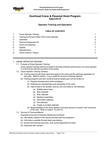
CAUTIONPINCH POINTHANDS CAN BE INJUREDKEEP HANDS AWAYFROM ROLLERSSafety Decal Locations4
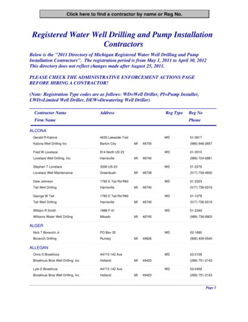
WARNINGArc Flash HazardAppropriate PPE RequiredDo not operate controls or open conerswithout appropriate personal protectionequipment.Failure to comply may result in injury ordeath!Refer to NFPA 70E for minimum PPE requirementsCAUTIONMoving parts canpinch or cut.Do not operatewith guard removed.Lockout and tagoutbefore servicing.Safety Decal Locations5
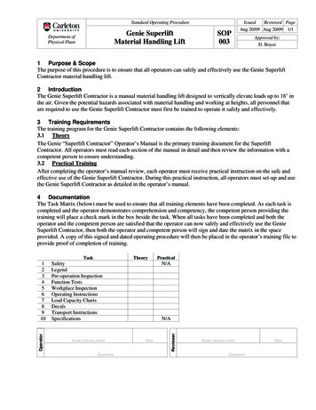
3ChapterLabeler SectionsOverviewThis manual covers several parts of the machine. Thefollowing diagram identifies the key sections of the machine.LET OFF DISCLET OFF SPINDLEDANCER BARREWIND DISCCONTROLLERREWIND SPINDLEIDLER ROLLERLABEL SENSORAPPLICATORTRAVERSE SCREW CLAMPAPPLICATORROLLER ORWIPE DOWNROLLERIDLER RELEASE KNOBREWIND CLIPKNURLED ROLL AND RUBBERROLL. TOGETHER THEY ARE THENIP ROLLASSEMBLYWEB GUIDE POSTS ANDWEB GUIDE RAILSDISPENSE BLADEU6
4ChapterInstallation and ThreadingBefore you can begin to install the labeler, confirm that the labeler is tobe used in a side mount application.Side labeling on a cartonCompleted side mounted labeler assemblyThe labeler can only label products that pass in a specificdirection. The diagram below shows the direction the productmust travel in relative to the labeler.Surface tobe labeled.7
S E C T I O N1 :P L A C I N GT H EM O U N TSection 1: Placing the MountThe LS-500P comes packaged with the 921 mount. ThePlant Manager at your facility might have already determined apre-arranged location for the labeler. If no pre-arranged locationexists following the steps below will help determine the ideal spot.Step One: Carefully remove all of the items in the shipping boxand locate item 21006 shown in the illustration below.Item 21006 must be mounted securely in a position that will allowthe labeler to contact the product at the point of label application on the LS500P. If a case sealer interface frame or H-mount has been purchased inconjunction with the labeler there will be holes already set to attach the base.If neither mount is available refer to the following dimensional drawing todetermine the best location for the base.21006 LocationPoint of Label Apply8
S E C T I O N1 :P L A C I N GT H EM O U N TStep Two: Take the large metal tube and place it in the labeler asshown below,Turn the Adjustment Knob to place the Traverse Screw Clamp in thecenter of the labeler. About four inches of tube should extend beyond theStop Collar. Once the tube is in position tighten the screw in the TraverseScrew Clamp and Stop Collar tightly.Step Three: The labeler weighs sixty-five pounds. It is highlyrecommended that one or more additional people assist you with the nexttwo steps. Once the cross tube is secured tightly in the labeler, return to thebase (21006) and make sure that it is open as wide as possible. Carefully placethe end of the tube into the base making sure that it is entirely within the base,if the labeler and tube wobble greatly the tube is not fully through. Rotate thelabeler so that the point of label application will gently contact the product andthen tighten the base handle.Step Four: Loosen the Stop Collar. Turn the Adjustment Handleuntil the bottom of the roller is aligned with where the bottom of the label willbe on the product. The labeler can only be adjusted up or down a maximumof 3 ½”. Located opposite the adjustment handle is the clamp lock knob.Turning this knob it is possible to lock the traverse screw clamp in positionbefore tightening the stop collar and prevent movement by accidentally9
S E C T I O N1 :P L A C I N GT H EM O U N Tbumping the adjustment knob when securing the stop collar. If furtheradjustment beyond 3 ½” is desired it is necessary to hold the labeler securelywhile loosening the screw in the Traverse Screw Clamp and lowering it by thedesired amount. After any adjustments in height, always be sure that theTraverse Screw Clamp and Stop Collar are tightly secured.Step Five: Enclosed with the labeler are two plastic discs (onewith a clamp collar and sensor), two thin metal discs, a black aluminum collar,and a thrust bearing. Place the items and your roll of labels on the labeler asshown below.Let off disc withmetal clamp collar.Collar facer up.Plain DiscThin metaldisc, thrustwasher.ThrustbearingBlack metalcollarLet off spindleIf any core adaptors are present (additional black collars or plasticsleeves) place single ones where the center of the label roll will be. If morethan one core adaptor is present, place the first one an inch above the plainplastic disc and the other one inch in from where the label roll ends at the top.Turn to Section 2: Threading Label Stock.10
S E C T I O N2 :T H R E A D I N GT H EL A B E LS T O C KSection 2: Threading the Label StockAlways make sure that the power is off, the unit is unplugged,and no product are moving past the labeler before threading new labelstock or threading re-threading after a web breaks. There is a quickreference sticker on the control side of the labeler showing thelabel path. Recommended label specifications can be found at theend of this manual and should be consulted when ordering newlabel rolls.Step One: Make sure that the let-off discs are not holding the label rolltoo tightly. The roll should spin when light pressure isapplied to it. On top and bottom applications, the labeler is mounted on a922-A, it is recommended that the labels be placed on thecenter of the let-off spindle and threaded through the centerof the machine. Make sure that when the leading edge of the label roll ispulled away, the labels face the top of the machine regardlessof the machine orientation to top, side, or bottom application.See Label stock windings below. Clear the first 36” of labels.Label StockWindings Labels wound outside (mount as shown)Labels wound inside (mount as shown)Step Two: Take the cleared strip of label web and thread it underthe dancer bar, over the rewind spindle, and under the idler roller.11
S E C T I O N2 :T H R E A D I N GT H EL A B E LS T O C KLabel rollDancer barLabel webTeflonidlerRewindspindleStep Four: Now take the web and pull it through the label sensor,through the web guide rails and over the dispense blade. To complete thispart of the threading process it may be necessary to loosen and slide thesensing head and web guide rails. When done, the web should appear as itdoes below.Label webLoosen thethumbscrewon the sensorhead and slideto this sideTeflonidler rollSlide web guideposts apart asseen and threadweb betweenboth railsLabel web goesunder the blackmetal plate androller12
S E C T I O N2 :T H R E A D I N GT H EL A B E LS T O C KStep Five: Open the idler roll with the idler releasehandle, the handle 90º (counter-clockwise for right hand;clockwise for left). Thread the web over the return roller,through the idler rollers up to the rewind spindle and clip in place.Close the nip roll.Idler Release HandleRewind ClipRewind SpindleLabel WebReturn Roll.Nip RollersApplicator Roll.The labeler is now threaded and ready to be plugged inand turned on. Pressing the orange 2nd key on the controller willdispense one label. Check that the label stops dispensing when itjust comes to the wipe down roller. If this does not happen, thelabel comes out too far or not far enough adjustments to the labelsensor and/or applicator may be needed. Read chapter 5 toadjust the label sensor and chapter 7 to adjust the applicator13
P H O T O E L E C T R I CL A B E LLabel SensingS E N S O R5ChapterPhotoelectric Label sensorThe LS-500P comes standard with a Photoelectric Labelsensor. The function of this piece is to stop the movement oflabels through the machine once the first label has cleared theapplicator and the next label is in position. The photo-eye locatedin the sensor head can see the labels and web without the need tocontact the web in any way. A web tension piece rides the sameshaft as the sensing head to keep the web at a steady distancewithin the photo-eye. The label sensor will already be mountedwithin the labeler must be plugged into the controller portmarked Label Sensor on the rear of the unit during installation.Refer to the illustrations below to adjust the label sensor to suityour specific label size(s) accordingly.ThumbscrewThumbscrewLED Indicator.Web tensioner. Itshould be alignedwith the center ofthe label web andapply moderatepressure to the webSensing Head.The label webshould notcontact anysurface of thesensing head andshould passthrough withoutresistance.Web guide posts.Place near web butnot to come intodirect contact withlabel web.14
P H O T O E L E C T R I CL A B E LSensor locking knobS E N S O RSensing head.LED indicator.Web tensioner.Loosening these screws willenable the web tensioner tomove up or down to increase.or decrease pressure on theweb if rotation is not possible.The LED indicator should be off when a label is present inthe sensor head and on when no label or empty web is present inthe sensing head.The label sensor assembly can be moved forward orbackward within the head by loosening the Sensor Locking Knoband sliding it to the desired position. Settings contained in thecontroller can allow the label to move beyond the point ofdetection. These settings are used to fine tune label placementwhen manual adjustment of the label sensor is insufficient. Tolearn how to do this, see Help Menu: Adjust in Chapter1015
P R O X I M I T Y6ChapterP H O T O - E Y EProductSensingProximity Photo-eyeThe labeler operates when it gets a signal from the productsensor telling it that the product is in place to receive the label. Astandard photoelectric eye comes packaged with the machine andplugs into the back of the controller on the port marked productsensor.PlugRemove plasticnut to slide offmount bracketfor alternatemounting stylesMountBracketA standard mounting bracket allows the photo-eye to bemounted to a conveyor or guide rail but must be placed so thatthe eye is no greater than 4 inches (10cm) away from the product.Select the position of the product sensor so that the product willpass in front of it when you want the label apply cycle to start.16
P R O X I M I T YP H O T O - E Y EProduct sensor locationLabelerLabel locationon side of boxProduct Flow.It is possible to adjust the label position on the box byadjusting the time between product detection and label apply. Tolearn how to do this turn to Help Menu: Adjust in chapter 1017
A D J U S T I N GT H EA P P L I C A T O RApplicator7ChapterAdjusting the ApplicatorThe applicator has only three adjustments; length, angle,and tension.Adjusting theApplicatorlengthExceptionally long labels (labels longer than 6”) may justifythe need to extend the distance between the wipe down roller andthe dispense blade edge if the label sensor adjustments cannotplace the label at the desired application point.Loosen or removescrews in slots and slideforward.Label should feed until itjust contacts the roller.18
A D J U S T I N GAdjusting theApplicatorAngleT H EA P P L I C A T O RIf the length of the applicator has been extended, it may benecessary to adjust the angle of the applicator so that it can reachthe product.Remove shoulderbolt and place in amore favorablehole towards rear.Use slot and holesto rotate arm.Adjusting theApplicatorTensionOver time the spring that applies pressure to the wiper roller maylose some firmness. When labels cease to be pressed firmly to theproduct adjusting the applicator tension may be necessary.Loosen collarand slide upon shaft.19
8ChapterFeatures andOptionsLow Label SensorAttached to one of the let off discs is a low label sensor.This sensor, when plugged in to the controller, will let the unitknow when the label stock is in small supply. When the labelsrun low a message on the controller will let the operator knowthat new roll of labels will soon need to be placed in the machine.Optional: Light TowerWhile the low label sensor is a standard feature of themachine, the light tower is an optional accessory. The light towershould be mounted near the labeler and plugged in to the back ofthe controller. When the low label sensor indicates that the labelroll is low the light tower turns on giving a highly visibleindication to all plant employees that a new roll of labels will beneeded shortly.20
9ChapterController OperationKeyboard, ScreenT he special-function keys on the keyboard have the following uses: HELP 2ND is the “jog“ key; pressing this key starts a label-cycle (see Jog below). The ÇÈ arrow keys move through menus and menu features. ENTER is used to complete an entry.shows the menu; CLEAR exits from the menu, and can be used todelete characters in the data entry screens.Power-On and UnlockWhen the unit is turned on the startup screen is shown; this appears below.Labeler modelSoftware versionController memory statusIf locked or clear appears on the memory status line unit parameters must beadjusted before labeling will occur.21
C O N T R O L L E RO P E R A T I O NTo unlock the unit, enter the factory code 5863434 followed by ENTER —except if the Unlock code feature has been used to change the code.READYIf memory wasn’t cleared, or after setting cleared parameters, the normal unitdisplay will appear showing the labeler is ready to operate. Memory ClearOnce the labeler is unlocked, it will usually show the READY legend. Ifinstead the Memory clear message appears, the unit memory is clear andlabeling parameters should be set by pressing the 1 key to enter the parametersection; see ADJUST menu, next chapter. Typically all parameter values foryour particular labeler installation should be written down in the back of thismanual or optionally on a decal somewhere within labeler vicinity of thelabeler and those values should be entered at this point; see Adjust below.22
ChapterUsing Help MenuFeatures10In normal operation, the labeler is simply turned-on and products aremoved past its sensor equipment and the labeler responds by applying alabel. To adjust system behavior including important labeler parameters,the Help Menu must be accessed with the HELP key. The unit thendisplays a list of numbered features, one of which may be selected by pressingthe number or letter next to it. The entire menu can’t be seen at once, so usethe arrow keys to move through it. It is not necessary to move in this way toan entry, it can be selected any time by pressing its associated number.shows the menu; CLEAR exits from the menu, and can be used todelete characters in features. To exit the help menu, press ENTER, HELP, orCLEAR.HELPThe following text describes each of the features in the help menu by name.The special-function keys on the keyboard have the following uses:How Help Menu Features WorkSelecting a typical feature will produce a prompt and a number, like Featurevalue: 0. To change the number, use the arrow keys, or press number keys.The system will automatically prevent values too large or small from beingentered. When the desired value is set, press ENTER. Many features adjusttiming and are set in milliseconds; 1,000 milliseconds equal one second.Several features use a similar arrangement, but only permit 0 or 1 as values, tocontrol an on/off or yes/no labeler function. 1 is on or yes, 0 is off or no. Recordall settings values on the chart in the back of this manual.23
C H A P T E R5 :L B L I N KA U T O M A T I O NC O N T R O LHelp Menu Feature 1: AdjustThe most important feature on the help menu is Adjust, which allows controlof labeler parameters. Selecting the feature produces another menu just likethe help menu, which is used in the same way and has the following entries.Note that some or all of these features will vary depending on the selectedunit (see Help Menu Feature 2: Select) and/or software version. Product Delay controls the time from product detection to start oflabeler activity; default setting is 250 milliseconds or ¼ second. Label Overfeed is the time from label sensor detect until label motorstop. A photoelectric sensor positions the label and stops when the labelhas moved to the right location. The hardware is deliberately designed sothat the sensor detects the label too early so it can be fine tuned with thisparameter. Hold-Off controls the minimum time from the end of a labeling cycle tothe beginning of the next cycle; this default value is 0.Help Menu Feature 2: SelectChoosing this menu item will simply display Not Implemented.Help Menu Feature 3: LanguageThe feature determines the language in which the Label Controller menusand other informative screens will be displayed. Pressing the arrow keys will“scroll” to show more of it. Then press the desired number.Allows selection 1. ENG, 2. ITAL, 3. DEUT, 4. FRAN, 5. ESPA, 6. DUTC, 7. PORTAvailable languages are English, Italian, German, French, Spanish, Dutch andPortuguese.Help Menu Feature 4: Net #Some labeler units can operate within a Loveshaw Corp network, allowingcontrol of multiple units from a central computer. In such networks eachunit must have a unique identifying number, which can be set in this feature.This feature is disabled if set to zero. If set to 1 thru 32 a special networkusing RS-422 may be possible. This selection changes from the normal RS-232point to point communications to a network Board. The optional Labels24
C H A P T E R5 :program is required.computers.L B L I N KA U T O M A T I O NC O N T R O LLabels is a Windows program that runs onPCHelp Menu Feature 5: SpeedThis feature sets the feed rate of the label so that it matches the conveyorspeed. It is entered in Inches per minute. If the rate is too slow the labelmight tear or drag/pull off the box and if set too fast the label will crinkle.Help Menu Feature 6: Unlock code The default unlock code 5863434 can be altered with this feature. Note thatonce it is altered if the new code is forgotten Loveshaw Corp cannot retrieveit and the unit will have to be cleared for features to be accessible again.Help Menu Feature 7: OtherThis menu contains factory setting specific to your application. Do not alterthe settings in this menu unless directed by Loveshaw Corp.Other Control Functions666 MemoryClearTo clear all memory in the labeler — if for instance, the unlock code hasbeen altered and then lost — turn the unit off, press and hold the number 6,turn the unit on, wait about a second, release the 6, then press 6, 6, followedby CLEAR, HELP, and the down arrow key È; if any error is made in pressingthe keys, the memory clear does not occur.JogIt is often desirable to cause the labeler hardware to execute a cycle withoutactual product processing; this is called a Jog. The 2ND key starts a jog cycle.NormalOperation;MemoryClearFailuresThe labeler will normally display the READY legend at power-on. When thelabeler receives a product signal or the Jog control is used (see above) labelcycling will occur and informative messages will appear describing the stagesof the cycle.If, however, memory is clear and parameters have not been adjusted; i.e. if 0instead of 1 is pressed at power-on in answer to the Memory clear; adjustparameters? question, then subsequently whenever the unit should start acycle, it will instead produce the memory clear prompt all over again. It iseasy to exit this prompt without actually adjusting parameters. Pressing 1followed by ENTER will leave parameters in a nominal default state, andduring installation could cause equipment malfunction.25
ChapterController HardwareNotes11The Label Controller is a 7" Width 6½" Depth 5½" Height enclosurewith a twist front piece. When installed it has a metal cover thatprotects it and the motor. This controller includes a 2 by 20 characterdisplay and 2 x 8 button keypad for data entry. This controllerinterfaces the Print Trigger Devices, solenoids, and other sensors to signal theStepper Motor or Printer to apply labels to the product.OverviewParts include:a) MicroJet Controller Board — is the CPU of the package it provides theuser with memory and control to the other subsystems.b) Driver Board — connects to the controller board to provided inputs fromsensors and outputs for the Motor AC Board/Stepper Board.c) The Motor AC and Stepper Board include the voltage power supplies,relays and motor/solenoid controls. These boards provide LED for a visualindication of the motor and solenoids. Two types of motors are available.The AC stepper motor is used with the Motor AC board and DC stepper motor is used with theStepper board. The power supply on this board has two fuses for the DC circuitry. A 3Amp fusefor the logic and an 8Amp for the stepper motor/relays (depending on the choice of motor thecurrent draw is 3Amp to 7Amp).d) A Keypad and LCD screen provide user-friendly interface. Both of these items are on a twistableplate.e) A power cord is plugged into a CORCOM. The CORCOM is selectable for 110/220. The AC StepperMotor is voltage specific either 110 or 220/240 VAC. The Stepper Board uses DC Stepper Motorand can allow for any voltage settings. Two 3Amp fuses are used in the CORCOM.26
S P E C I F I C A T I O N Sf) An RS-232 port is selected standard but included is a jumper changeable to an RS-422 network.External Inputs JP7 — Label Sensor AnalogPH3 — Label Sensor DigitalPH4 — Motor Lock-OutPH5 — Stop SolenoidPH6 — Inhibit SolenoidPH7 — Product SensorPH9 Low Label InputProduct Sensor9 Pin DJP7 12 VDC61signal NO32signal NC23ground54Label Sensor9 Pin D 12VDC6signal3output2ground5PH71234To use switch from the standard Analog sensor to the Digital with built-in amplifier remove U14 anduse PH3.Interconnect Cables Between The PC And The LabelControllers.Default setup is RS-232. RS-232 connection is a point-to-point connection where only one COM portmay be connected to one Label Controller. A maximum cable length is 300 feet using Braided ShieldExtended Quite Cable.DB92 (RXD)3 (TXD)5 (GND)ShieldDB253 (TXD)2 (RXD)7 (GND)ShieldLabel Controller DB92 (TX)3 (RX)5 (Ground)Shield27
S P E C I F I C A T I O N SSome RS-232 boards have different pin-outs, review hardware provided documentation. If RS-232 isused only one unit can be connected to a Windows computer using multitasking. Only one LabelController can be connected to one RS-232 system at one time. If more units have to be connected orif the cable length is longer than 300 feet, RS-422 must be used. RS-422 allows for up to 32 LabelController units to be connected to each COM port.RS-422connection is a multi drop connection. The PC is the master and the Label Controllers are theslaves to it. A maximum cable length is 1000 feet.From Master (PC)TXD(PC) (H or ) to RXDRXD(PC) (H or ) to TXDGround(PC) to Ground(Labeler)to Slave (Labeler)(H or ) TXD(PC) (L or -) to RXD (L or -)(H or ) RXD(PC) (L or -) to TXD (L or -)pin 5 Shield(PC) to Shield(Labeler)All units have RS-422; the second Interface connector is used to loop more than one controller.Switching from RS-232 to RS-422 requires a cable and jumper change. RS-232 connection is on theright internal driver board RS2 labeled RS-232. On the Left is RS7 labeled RS-422. Change this ribboncable connection. It is selected by 3rd pin of RS6 from the two right pins to the two left pins. The lastunit must only have pull up resistors on it therefore remove RS4 and RS5 jumper if not the last unit.The cable is specified below.PinSignal Name12359RS485 TXRS485 RX RS485 RXDC GroundRS485 TX Type Labeler ControllerSignalsOutputInputInputGroundOutputEach RS485 board has different pin-outs, review the documentation provided by the boardmanufacturer. The prov
labeler should nk you for purchasing the newest Little David labeler, the LS-0P. The LS-500P is the low cost labeler designed to be versatile ough to suit a variety of carton labeling requirements with one ndard unit. All employees who will be required to operate the read this manual to ensure proper set-up and a longer machine life.