Transcription
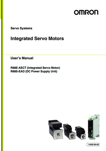
Servo SystemsIntegrated Servo MotorsUser’s ManualR88E-AECT (Integrated Servo Motor)R88S-EAD (DC Power Supply Unit)I103E-EN-02
OMRON, 2017All rights reserved. No part of this publication may be reproduced, stored in a retrieval system, or transmitted, in anyform, or by any means, mechanical, electronic, photocopying, recording, or otherwise, without the prior writtenpermission of OMRON.No patent liability is assumed with respect to the use of the information contained herein. Moreover, because OMRONis constantly striving to improve its high-quality products, the information contained in this manual is subject to changewithout notice. Every precaution has been taken in the preparation of this manual. Nevertheless, OMRON assumes noresponsibility for errors or omissions. Neither is any liability assumed for damages resulting from the use of theinformation contained in this publication.Trademarks Sysmac and SYSMAC are trademarks or registered trademarks of OMRON Corporation in Japan and other countriesfor OMRON factory automation products. Windows, Windows XP, Windows Vista, Windows 7, Windows 8, Windows 10 and Excel are registered trademarksof Microsoft Corporation in the USA and other countries. EtherCAT is registered trademark and patented technology, licensed by Beckhoff Automation GmbH, Germany. ODVA, CIP, CompoNet, DeviceNet, and EtherNet/IP are trademarks of ODVA.Other company names and products names in this document are the trademarks or registered trademarks of theirrespective companies.
IntroductionIntroductionThank you for purchasing an Integrated Servo Motor Series. This manual explains how to install andwire the Integrated Servo Motor, set parameters needed to operate the Integrated Servo Motor, andremedies to be taken and inspection methods to be used if problems occur.Intended ReadersThis manual is intended for the following individuals.Those having electrical knowledge (certified electricians or individuals having equivalent knowledge)and also being qualified for one of the following: Introducing FA equipment Designing FA systems Managing FA sitesNoticeThis manual contains information you need to know to correctly use the Integrated Servo Motor andperipheral equipment. Before using the Integrated Servo Motor, read this manual and gain a fullunderstanding of the information provided herein.After you finished reading this manual, keep it in a convenient place so that it can be referenced at anytime.Make sure this manual is delivered to the end user.Integrated Servo Motor User’s Manual1
Read and Understand this ManualRead and Understand this ManualWarranty and Limitations of LiabilityWARRANTYOMRON's exclusive warranty is that the products are free from defects in materials and workmanship for a period ofone year (or other period if specified) from date of sale by OMRON.OMRON MAKES NO WARRANTY OR REPRESENTATION, EXPRESS OR IMPLIED, REGARDINGNONINFRINGEMENT, MERCHANTABILITY, OR FITNESS FOR PARTICULAR PURPOSE OF THE PRODUCTS.ANY BUYER OR USER ACKNOWLEDGES THAT THE BUYER OR USER ALONE HAS DETERMINED THAT THEPRODUCTS WILL SUITABLY MEET THE REQUIREMENTS OF THEIR INTENDED USE. OMRON DISCLAIMS ALLOTHER WARRANTIES, EXPRESS OR IMPLIED.LIMITATIONS OF LIABILITYOMRON SHALL NOT BE RESPONSIBLE FOR SPECIAL, INDIRECT, OR CONSEQUENTIAL DAMAGES, LOSS OFPROFITS OR COMMERCIAL LOSS IN ANY WAY CONNECTED WITH THE PRODUCTS, WHETHER SUCHCLAIM IS BASED ON CONTRACT, WARRANTY, NEGLIGENCE, OR STRICT LIABILITY.In no event shall the responsibility of OMRON for any act exceed the individual price of the product on which liabilityis asserted.IN NO EVENT SHALL OMRON BE RESPONSIBLE FOR WARRANTY, REPAIR, OR OTHER CLAIMS REGARDINGTHE PRODUCTS UNLESS OMRON'S ANALYSIS CONFIRMS THAT THE PRODUCTS WERE PROPERLYHANDLED, STORED, INSTALLED, AND MAINTAINED AND NOT SUBJECT TO CONTAMINATION, ABUSE,MISUSE, OR INAPPROPRIATE MODIFICATION OR REPAIR.2Integrated Servo Motor User’s Manual
Read and Understand this ManualApplication ConsiderationsSUITABILITY FOR USEOMRON shall not be responsible for conformity with any standards, codes, or regulations that apply to thecombination of products in the customer's application or use of the products.At the customer's request, OMRON will provide applicable third party certification documents identifying ratings andlimitations of use that apply to the products. This information by itself is not sufficient for a complete determination ofthe suitability of the products in combination with the end product, machine, system, or other application or use.The following are some examples of applications for which particular attention must be given. This is not intended tobe an exhaustive list of all possible uses of the products, nor is it intended to imply that the uses listed may besuitable for the products: Outdoor use, uses involving potential chemical contamination or electrical interference, or conditions or uses notdescribed in this manual. Nuclear energy control systems, combustion systems, railroad systems, aviation systems, medical equipment,amusement machines, vehicles, safety equipment, and installations subject to separate industry or governmentregulations. Systems, machines, and equipment that could present a risk to life or property. Please know and observe allprohibitions of use applicable to the products.NEVER USE THE PRODUCTS FOR AN APPLICATION INVOLVING SERIOUS RISK TO LIFE OR PROPERTYWITHOUT ENSURING THAT THE SYSTEM AS A WHOLE HAS BEEN DESIGNED TO ADDRESS THE RISKS,AND THAT THE OMRON PRODUCTS ARE PROPERLY RATED AND INSTALLED FOR THE INTENDED USEWITHIN THE OVERALL EQUIPMENT OR SYSTEM.PROGRAMMABLE PRODUCTSOMRON shall not be responsible for the user's programming of a programmable product, or any consequencethereof.Integrated Servo Motor User’s Manual3
Read and Understand this ManualDisclaimersCHANGE IN SPECIFICATIONSProduct specifications and accessories may be changed at any time based on improvements and other reasons. It isour practice to change model numbers when published ratings or features are changed, or when significantconstruction changes are made. However, some specifications of the products may be changed without any notice.When in doubt, special model numbers may be assigned to fix or establish key specifications for your application onyour request. Please consult with your OMRON representative at any time to confirm actual specifications ofpurchased products.DIMENSIONS AND WEIGHTSDimensions and weights are nominal and are not to be used for manufacturing purposes, even when tolerances areshown.PERFORMANCE DATAPerformance data given in this manual is provided as a guide for the user in determining suitability and does notconstitute a warranty. It may represent the result of OMRON's test conditions, and the users must correlate it toactual application requirements. Actual performance is subject to the OMRON Warranty and Limitations of Liability.ERRORS AND OMISSIONSThe information in this manual has been carefully checked and is believed to be accurate; however, no responsibilityis assumed for clerical, typographical, or proofreading errors, or omissions.4Integrated Servo Motor User’s Manual
Safety PrecautionsSafety Precautions To ensure that the Integrated Servo Motor as well as peripheral equipment are used safely and correctly, besure to read this Safety Precautions section and the main text before using the product in order to learn itemsyou should know regarding the equipment as well as required safety information and precautions. Make an arrangement so that this manual also gets to the end user of this product. After reading this manual, keep it in a convenient place so that it can be referenced at any time.Definition of Precautionary Information The precautions explained in this section describe important information regarding safety and must be followedwithout fail. The display of precautions in this manual and their meanings are explained below.DANGERCautionIndicates an imminently hazardous situation which,if not avoided, will result in death or serious injury.Additionally, there may be severe property damage.Indicates a potentially hazardous situation which,if not avoided, may result in minor or moderateinjury, or property damage.Even those items denoted by the caution symbol may lead to a serious outcome depending on thesituation. Accordingly, be sure to observe all safety precautions.Precautions for Safe UseIndicates precautions on what to do and what not to do to ensure using the product safely.Precautions for Correct UseIndicates precautions on what to do and what not to do to ensure proper operation andperformance.Additional InformationIndicates an item that helps deepen your understanding of the product or other useful tip.Integrated Servo Motor User’s Manual5
Safety PrecautionsExplanation of SymbolsExample of symbolsThis symbol indicates danger and caution.The specific instruction is indicated using an illustration or text inside or nearThe symbol shown to the left indicates “beware of electric shock.”.This symbol indicates a prohibited item (an item you must not do).The specific instruction is indicated using an illustration or text inside or nearThe symbol shown to the left indicates “disassembly prohibited,”.This symbol indicates a compulsory item (an item that must be done).The specific instruction is indicated using an illustration or text inside or nearThe symbol shown to the left indicates “grounding required,”.Recipients Only specialized staff can modify the drives of the Integrated Servo Motor series and use them, who previouslyread the manual and all the documents related to the product. Specialized staff must have been adequatelytrained about safety in order to prevent any possible risks. The technical training, foreground and experience ofthe specialized staff must help them preventing from any possible risk occurring during the product use, fromthe settings modification to the functioning of the mechanical, electrical and electronic equipment of the device.The specialized staff must know all the current regulations and safe working practices in case of any intervention on the product. This manual must be read by the following staff members: Transport: Only for personnel expert in handling sensitive parts of electrostatic charges. Unpacking: Only for qualified electricians. Installation: Only for qualified electricians. Use: Only for qualified staff expert in electro-technology and activation technology. The qualified staff must know and follow these rules: EN 12100, EN 60364 and EN 60664. National safe working practices. This manual is addressed to all users of the Integrated Servo Motor.DANGERDuring the drive functioning beware of danger of death, serious injuries or material damage.For a safe functioning, follow all the safety instructions in this manual. The security officermust check that the staff working with the drives read and understood this manual beforeusing them.6Integrated Servo Motor User’s Manual
Safety PrecautionsResponsibilitiesCautionOMRON can modify the described products in this manual in any time and without anynotice.This manual was written by OMRON only for their customers use providing the mostupdated version of the products.The responsibility to use this manual belongs to every user and the use of some functionsmust be under strict care to avoid any danger for the staff and the equipment.No other warranty is provided by OMRON in particular for possible imperfections,incompleteness, and/or any other difficulties.Precautions for Safe Use of This Product Illustrations contained in this manual sometimes depict conditions without covers and safety shields for the purpose of showing the details. When using this product, be sure to install the covers and shields as specified anduse the product according to this manual. If the product has been stored for an extended period of time, contact your OMRON sales representative.General Dangers and CautionsDANGERAlways connect the ground terminals to a type-D or higher ground. Improper grounding mayresult in electrical shock.This product is intended to be exclusively used in machines and systems in industrialenvironment, respecting the described application, environmental and functioningconditions. Follow the safety regulations and the ordinances of the country in which theproduct (or the relative control and command system) is used.Never touch the parts inside the Integrated Servo Motor. Electric shock may result.While the power is supplied, do not remove the front cover, terminal covers, cables, andoptions. Electric shock may result.Installation, operation, and maintenance or inspection by unauthorized personnel isprohibited. Electric shock or injury may result.Before carrying out wiring or inspection, turn OFF the main circuit power and wait for atleast 1 minute. Electric shock may result.Do not damage, pull, stress strongly, or pinch the cables or place heavy articles on them.Electric shock, stopping of Drive operation, or burn damage may result.Integrated Servo Motor User’s Manual7
Safety PrecautionsNever touch the rotating part of the Integrated Servo Motor during operation. Injury mayresult.Never modify the products. Injury or equipment damage may result.Install a stopping device on the machine to ensure safety.* The holding brake is not a stopping device to ensure safety. Injury may result.Install an immediate stop device externally to the machine so that the operation can bestopped and the power supply cut off immediately. Injury may result.When the power is restored after a momentary power interruption, the machine may restartsuddenly. Never come close to the machine when restoring power.* Implement measures to ensure safety of people nearby even when the machine isrestarted. Injury may result.After an earthquake, be sure to conduct safety checks. Electric shock, injury, or fire mayresult.Never drive the Integrated Servo Motor using an AC Power Supply. Fire may result.Never drive the Integrated Servo Motor using an external drive source. Fire may result.Do not place flammable materials near the Integrated Servo Motor or DC Power SupplyUnit. Fire may result.Install the Integrated Servo Motor and DC Power Supply Unit on non-flammable materialssuch as metals. Fire may result.Do not use the cable when it is laying in oil or water. Electric shock, injury, or fire may result.Use always a suitable power supply like the R88S-EA to supply the Integrated Servo Motor.Fire or failure may result.Do not perform wiring or any operation with wet hands. Electric shock, injury, or fire mayresult.Do not touch the key grooves with bare hands if a Integrated Servo Motor with shaft-endkey grooves is being used. Injury may result.The Integrated Servo Motor and DC Power Supply Unit may become hot while the power issupplied or remain hot for a while even after the power supply is cut off. Never touch thesecomponents. A burn injury may result.8Integrated Servo Motor User’s Manual
Safety PrecautionsStorage and TransportationCautionDo not store or install the Integrated Servo Motor in the following locations: Location subject to direct sunlight Location where the ambient temperature exceeds the specified level Location where the relative humidity exceeds the specified level Location subject to condensation due to rapid temperature changes Location subject to corrosive or flammable gases Location subject to high levels of dust, salt content, or iron dust Location subject to splashes of water, oil, chemicals, etc. Location where the Integrated Servo Motor may receive vibration or impact directlyInstalling or storing the Integrated Servo Motor in any of these locations may result in fire,electric shock, or equipment damage.Do not overload the Integrated Servo Motor. (Follow the instructions on the product label.)Injury or failure may result.Use the original box to transport the Integrated Servo Motor. Product damage may occur.Do not transport the Integrated Servo Motor by holding it by the shaft. Product damage mayoccur.Integrated Servo Motor User’s Manual9
Safety PrecautionsInstallation and WiringCautionDo not step on the Integrated Servo Motor or place heavy articles on it. Injury may result.Install the Integrated Servo Motor in a place with sufficient ventilation. Fire or failure mayresult.Be sure to observe the mounting direction of the DC Power Supply Unit. Failure may result.Do not apply strong impact on the Integrated Servo Motor shaft or DC Power Supply Unit.Failure may result.Wire the cables correctly and securely. Runaway Integrated Servo Motor, injury, or failuremay result.Securely tighten the mounting screws, terminal block screws, and cable screws. Failuremay result.Use crimp terminals for wiring. If simple twisted wires are connected directly to theprotective ground terminal, fire may result.Only use the power supply voltage specified in this manual. Burn damage may result.In locations where the power supply infrastructure is poor, make sure the rated voltage canbe supplied. Equipment damage may result.Provide safety measures, such as a breaker, to protect against short circuiting of externalwiring. Fire may result.If the Integrated Servo Motor is used in the following locations, provide sufficient shieldingmeasures. Location subject to noise e.g., due to static electricity Location subject to a strong electric or magnetic field Location where exposure to radioactivity may occur Location near power supply linesUsing the Integrated Servo Motor in any of these locations may result in equipment damageConnect a 24 VDC control power supply with enough current capacity, specially if motorwith brake is used. Injury or failure may result.When connecting the power supply, make sure the polarity is correct. The drive is notprotected against reversed polarity. Damage or explosion may result.10Integrated Servo Motor User’s Manual
Safety PrecautionsOperation and AdjustmentCautionConduct a test operation after confirming that the equipment is not affected.Equipment damage may result.Before operating the Integrated Servo Motor in an actual environment, check if it operatescorrectly based on the parameters you have set. Equipment damage may result.Never adjust or set parameters to extreme values, because it will make the operationunstable. Injury may result.Separate the Integrated Servo Motor from the mechanical system and check its operationbefore installing the Integrated Servo Motor to the machine. Injury may result.If an error occurs, remove the cause of the error and ensure safety, and then reset thealarm and restart the operation. Injury may result.Do not use the built-in brake of the Integrated Servo Motor for normal braking operation.Failure may result.Do not operate the Integrated Servo Motor connected to an excessive load inertia. Failuremay result.Install safety devices to prevent idling or locking of the electromagnetic brake or the gearhead, or leakage of grease from the gear head. Injury, damage, or taint damage result.If the Integrated Servo Motor fails, cut off the power supply to the Integrated Servo Motor atthe power supply. Fire may result.Do not turn ON and OFF the main Integrated Servo Motor power supply frequently.Failure may result.Integrated Servo Motor User’s Manual11
Safety PrecautionsMaintenance and InspectionCautionAfter replacing the Integrated Servo Motor, transfer to the new Integrated Servo Motor alldata needed to resume operation, before restarting operation. Equipment damage mayresult.Never repair the Integrated Servo Motor by disassembling it. Electric shock or injury mayresult.Be sure to turn OFF the power supply when the Integrated Servo Motor is not going to beused for a prolonged period of time. Injury may result.The drive has rotary DIP switches to set the node number. All this settings must be madewhen the drive is switched off. To prevent damages to the drive it’s recommended to payparticular attention when working on this settings because in the drive there are somecomponents that are sensitive to the electrostatic discharge. It’s in particular advisable topreventively discharge the static electricity, to place the drive on a conductive support andto avoid contact with highly insulating materials. BEFORE TO POWER THE SYSTEM,REMEMBER TO FASTEN THE TRANSPARENT COVER (if it has been removed).When there is a fault, the drive is disabled; before enabling it again by rebooting the systemor by some correct commands through the field bus, remove the cause generating the fault.12Integrated Servo Motor User’s Manual
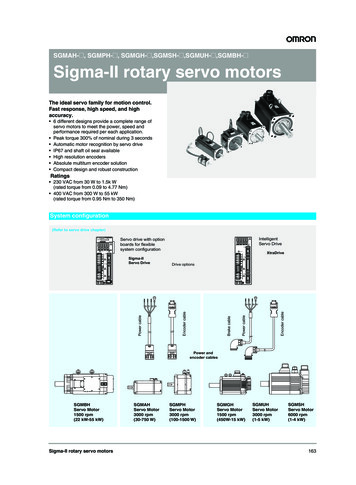
Safety PrecautionsMechanical Installation PrecautionCautionAmbient temperature: 0 to 40ºC40OK0ºCAmbient humidity: 95% RH max. (with no condensation)Vibration resistance: According to IEC 60068-2-6 (5 to 500 Hz, 1 and 2 G in 3 axes)Shock resistance: According to IEC 60068-2-27 (3 shock per axis, 11 ms, 14G)The protection class indicates the degree of protection required to keep dust and water fromentering.Protection class: IP65SpecifiedconnectorsShaft openingBe careful not to subject the shafts to any force or shock when installing the coupling. Whenconnecting with machines, make sure the axial load and thrust loads do not exceed themaximum allowable values specified in the user’s manual.Integrated Servo Motor User’s Manual13
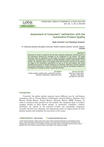
Safety PrecautionsCautionNever insert insulators, such as packings, in the joint between the Integrated Servo Motorand the heat sink.The insulator will not only cause the motor temperature to rise but also affect the noiseimmunity and result in Integrated Servo Motor failure.Install the Integrated Servo Motor in a well ventilated place and attached to a heatsink ormachine frame with suitable dimensions to guarantee a heat dissipation. Motor failure mayhappen.Integrated Servo MotorHeat sinkThe required accuracy for alignment differs depending on the Integrated Servo Motor speedand the model of the coupling. The maximum allowed deviation for alignment is 0.03 mm. Ifunusual sounds come from the coupling, readjust the alignment of the coupling until thesound is gone.0.03 mm max.Turn both the Integrated Servo Motor shaft and the machine shaft to align the coupling.Disposal Dispose of the Integrated Servo Motor and the DC Power Supply Unit as industrial wastes.14Integrated Servo Motor User’s Manual
Items to Check after UnpackingItems to Check after UnpackingAfter unpacking, check the following items. Is this the model you ordered? Was there any damage sustained during shipment?AccessoriesThe Integrated Servo Motor package includes: Integrated Servo Motor Plastic cap for the M8 connector “Dust cover” plastic cap for the M23 I/O connector Torx key Integrated Servo Motor instruction sheetNote No flying connector or cable is included in the standard equipment.The DC Power Supply Unit package includes: DC Power Supply Unit 2 flanges for connection of power cable shield x1, x2, x3, x5, x6, x7, x8 connectors DC Power Supply instruction sheetNote No cable is included as standard.Before you start working with the Integrated Servo Motor and the DC Power Supply Unit, verify thatthere are not visible damages. Be sure that the Integrated Servo Motor and the DC Power Supply Unitthat you have taken from the package are the correct models for your application, that corresponds towhat you have ordered and that you can provide a voltage supply as prescribed for the system.Integrated Servo Motor User’s Manual15
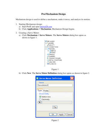
Items to Check after UnpackingChecking the nameplateIntegrated Servo Motor nameplateDC Power Supply Unit nameplate16Integrated Servo Motor User’s Manual
Revision HistoryRevision HistoryThe manual revision code is a number appended to the end of the catalog number found in the bottomleft-hand corner of the front or back cover.ExampleCat. No. I103E-EN-02Revision codeRevisioncodeRevision Date01May 201502October 2017Revised contentOriginal productionManual updated for R88E-AECT firmware 32: Section 7-2-4 Gear Mode was included New parameters included: FieldWeakeningFilterType [3520.06] FeedbackSensorResolution [36C0.02] FeedbackSensorPhasing [36C2.xx] MasterPositionSettings [4288.xx] TargetGearRatio [4289.xx] StartGearRatio [428A.xx] EtcResetPdoRxLostMaxConsecReset [5FF6.10] SysMngStatus [5FF7.02] SysMngMicroStepCurrent [5FF7.0A] Parameters updated: CaptureSources A [4003.xx] CaptureSources B [4013.xx] HomingStatus [42A1.00] SysMngCommand [5FF7.01] SysMngError [5FF7.03] FirmwareStatus [5FFE.01] QuickStopConfiguration [605A.00] ModesOfOperation [6060.00] ModesOfOperationDisplay [6061.00] HomingMethod [6098.00] MotorTemperatureSensorType [6410.0F]Integrated Servo Motor User’s Manual17
Structure of This DocumentStructure of This DocumentThis manual consists of the following chapters.Read the necessary chapter or chapters referring the following table.Outline18Chapter 1Features andSystemConfigurationThis section explains the features of the Integrated Servo Motor, nameof each part and applicable EC Directives.Chapter 2Models andExternalDimensionsThis section explains the models of Integrated Servo Motor andperipheral devices, and provides the external dimensions andmounting dimensions.Chapter 3SpecificationsThis section provides the general specifications, characteristics,connector specifications, and I/O circuits of the Integrated ServoMotor as well as the general specifications, characteristics, encoderspecifications and other peripheral devices.Chapter 4System DesignThis section explains the installation conditions for the IntegratedServo Motor and DC Power Supply Unit, wiring methods includingwiring conforming to EMC Directives and regenerative energycalculation methods.Chapter 5EtherCATCommunicationsThis section describes EtherCAT communications under theassumption that the Integrated Servo Motor is connected to a MachineAutomation Controller NX/NY/NJ-series.Chapter 6DC PowerSupply UnitSetupThis section describes how to setup the Power Supply Unit.Chapter 7Basic ControlModesThis section describes the modes that is used to control the IntegratedServo Motor.Chapter 8AppliedFunctionsThis section outlines the applied functions and explains the settings.Chapter 9/STOP FunctionThis section gives an outline of application functions and explains thesettings.Chapter 10 Details ofObjectsThis section explains the set values and contents of each object.Chapter 11 OperationThis section gives the operating procedures and explains how tooperate in each mode.Chapter 12 AdjustmentFunctionsThis section explains the functions, setting methods, and items to noteregarding various gain adjustments.Chapter 13 TroubleshootingandMaintenanceThis section explains the items to check when problems occur, errordiagnosis using the error display and measures, error diagnosis basedon the operating condition and measures, and periodic maintenance.AppendicesThe appendix provides the lists of objects, Sysmac Studio setup andother information.Integrated Servo Motor User’s Manual
Structure of This DocumentIntegrated Servo Motor User’s Manual19
CONTENTSCONTENTSIntroduction . 1Read and Understand this Manual . 2Safety Precautions . 5Items to Check after Unpacking. 15Revision History . 17Structure of This Document . 18Contents. 20Section 11-1Features and System ConfigurationOutline . 1-21-1-11-1-21-1-31-21-3System Configuration . 1-5Names and Functions . 1-61-3-11-3-21-3-31-3-41-4Section 22-2Integrated Servo Motor Configuration. 2-2How to Read Model Numbers . 2-3Integrated Servo Motor Model Table . 2-4DC Power Supply Unit Model Table . 2-4Cable and Peripheral Device Model Table . 2-5External and Mounting Dimensions . 2-72-4-12-4-220Integrated Servo Motor . 2-3DC Power Supply Unit . 2-3Model Tables . 2-42-3-12-3-22-3-32-4EC Directives . 1-12Models and External Dimensions2-2-12-2-22-3Integrated Servo Motor Block Diagram . 1-10DC Power Supply Unit Blo
6 Integrated Servo Motor User's Manual † Only specialized staff can modify the drives of the In tegrated Servo Motor series and use them, who previously read the manual and all the documents related to the product. Specialized staff must have been adequately trained about safety in order to prevent any possible risks.