Transcription
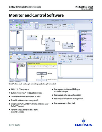
DeltaV Distributed Control SystemsProduct Data SheetNovember 2018Monitor and Control SoftwareDeltaV allows you to use the right control language for the right control task. IEC61131-3 languages Built-in Foundation fieldbus technology Control in the field, controller, or both Scalable software meets any needs Integrates multi-vendor real-time data into yourDeltaV system Perform calculations on data fromexternal sources Features protecting and hiding ofcontrol strategies Features class-based configuration Features advanced unit management Features advanced control
Monitor and Control SoftwareIntroductionAre you looking for a control system that allows you to usestandard control languages and functions? Do you want touse different control languages that are appropriate for thecontrol task within the same strategy? Do you want a controlsystem that permits you to design where and how you performmonitoring and control, rather than forcing you to fit within theconstraints of a fixed architecture? A DeltaV system gives youall this and more. Choose from IEC61131-3 control languagesand Foundation fieldbus function blocks to design yourmonitoring and control strategies.Need to consolidate your PLC, legacy systems, and gaugingsystems into a single operator interface? OPC may be used totear down the barriers between your legacy control systemsand your DeltaV system. The DeltaV system provides you witha real-time database where you can store third-party data foruse anywhere within the DeltaV system. You can display, trend,alarm and even use it in control strategies. What’s more, youchoose the location that is best for integrating the data into theDeltaV system, the workstation or the controller.This document details the monitoring and control functionssupported by a DeltaV system. These functions can run onDeltaV Application Stations and controllers and many of thefunction blocks may be assigned to run within Foundationfieldbus devices.BenefitsUses IEC61131-3 control languages. A DeltaV systemsupports three languages, so you can always use the toolsmost appropriate for the job. Function Block Diagrams (FBD),Sequential Function Charts (SFC), and Structured Text (ST)are all available, making control strategy development bothintuitive and easy.Built-in Foundation fieldbus functionality. These functionblocks are used throughout the DeltaV system. Controlstrategies are developed, using these standards based blocksthat minimize development time and maximize the system’sperformance. Many functions (like override control, tracking,and state control) are built into these powerful blocks. Plus,with Fieldbus, you get decreased wiring costs and improvedinstrument diagnostics.Control in the field, controller, or both. Design controlstrategies to meet your application requirements. Then decidewhere each block executes: in the controller, in the fielddevices, or both.www.emerson.com/deltavNovember 2018Scalable software meets any needs. As your needs grow,your DeltaV system is ready to expand with you. Additionalcapacity and even additional control functionality can be addedonline while you continue to control your process. Your entireconfiguration remains intact; you simply add to existing controlstrategies with the newly available functions or configure newcontrol modules to take advantage of higher capacity.Integrates multi-vendor data. Bring data into your DeltaVsystem for control, display, and historical purposes. Whenexecuting in the controller, the monitoring software usesClassic I/O, HART, Foundation fieldbus, PROFIBUS DP, AS-ibus, DeviceNet and serial interfaces to access data. Runningin workstations, OPC classic and OPC UA provides DataAcquisition control software with fast connections and datatransfers to and from any system. In addition, the EthernetI/O Card (EIOC) also supports Ethernet based devices thatcommunicate via the following protocols: OPC UA client,EtherNet/IP, Modbus TCP and IEC61850 MMS.Performs calculations on data from external sources. Nowyou can put the data from an existing system to work for you inthe DeltaV system. All DeltaV applications can access and usethe external data as if it were native DeltaV data. And becauseyou can execute function blocks directly in the workstation, youcan really put this external data to work for you.Features protecting and hiding of control strategies. Accessto library items like module templates and class definitionscan be restricted to enforce project standards. The internalstructure of modules can be hidden to protectintellectual property.Features class-based configuration. Build module classdefinitions for commonly used control (e.g. motors, valves) andequipment (e.g. valve header) modules. All module instancesthat are created from a definition inherit changes that are madeto the definition.Features advanced unit management (AUM). Usepowerful DeltaV unit modules and aliasing to write genericlogic in control and equipment modules. This will simplifyconfiguration management where there are similar equipmentunits or trains. Refer to the Advanced Unit Managementproduct data sheet for further details.Features advanced control. Use DeltaV Fuzzy to improveperformance of non-linear or noisy loops. The optional DeltaVInsight Tuning capabilities makes adjusting the Fuzzy rulesand PID parameters a snap. Simply run the tuning wizard andyour loop is optimized. For more demanding process controlrequirements, you can use Model Predictive Control or DeltaVNeural. Refer to the Advanced Control and DeltaV Insightproduct data sheets for details.2
Monitor and Control SoftwareProduct DescriptionDeltaV Monitoring and Control Software uses standardIEC61131-3 control languages, as well as Foundation fieldbusfunction blocks to support strategy development. Thesestrategies may be graphically assembled and modified usingstandard drag-and-drop techniques. Strategy development isvisually intuitive, making it easy for first-time users to quicklybecome productive. Context sensitive, online help is availablefor all functions. The IEC61131-3 control languages includeFunction Block Diagramming (FBD), Sequential Function Charts(SFC), and Structured Text (ST). Typical uses of each languageare listed below.Control Language Typical UsagesFunction Block Diagram (FBD)Monitoring and alarmingContinuous calculationsAnalog control (pressure, temperature, flow)Motor and block valve controlTotalizersSequential Function Chart (SFC)Charging systemsStartup/shutdown controlBatch sequences (fill, mix, heat, dump)Structured Text (ST)Advanced math functionsComplex calculationsInterlock condition detectionIf-then-else decisions LoopingBit manipulationswww.emerson.com/deltavNovember 2018Function Block Diagrams. Your DeltaV system uses FunctionBlock Diagrams to implement continuously executingcalculations, process monitoring, and control strategies.Graphical “wires” are used to connect the different blocks withina diagram. Each wire transfers one or more pieces of data. Allcommunications throughout the DeltaV system are handledautomatically. DeltaV function blocks are implemented usingthe structure specified by the Foundation fieldbus standard, butthey are also enhanced to provide greater flexibility in controlstrategy design. Foundation fieldbus -compliant Function Blocksenable you to take advantage of control in the field. You designcontrol strategies that best meet your control applicationrequirements. Then, decide whether the function blockscontrolling the process run in the controller, field devices,or both.Sequential Function Charts. This language enables you toconfigure operator-independent time-variant actions. SFCs arebest at controlling strategies with multiple states. They can beused for sequencing and simple batch applications.An SFC comprises a series of steps and transitions. Each stepcontains a set of actions that affect the process. Transitionsdetermine when processing moves on to the next step(s). Bothsingle-stream and parallel execution of logic is supportedwithin SFCs.Structured Text. With structured text you can writesophisticated calculations using a wide array of algebraic andtrigonometric functions and operators. In addition, you canbuild complex logic expressions using conditional anditerative structures.Data Acquisition. Display, trend, alarm, and use third partydata as if it were native DeltaV data. Now you can put the datafrom an existing system to work for you in a DeltaV system.All DeltaV applications can access and use the external dataas if it were native DeltaV data. The data can be used on anyDeltaV workstation. It can also be integrated into controlstrategies, consolidated into reports, historized, and muchmore. Whether your application utilizes the OPC Classic orOPC UA capabilities of the workstation, or the controller’s I/Osubsystem—once accessed, the real-time database makes thedata immediately available throughout the DeltaV system. Inruntime, the exception reporting mechanism moves the data tothe appropriate system application. The global configurationdatabase makes management and use of this data easy.3
Monitor and Control SoftwareNovember 2018Section 1: Function BlocksThe available DeltaV DCS function blocks and their descriptions are listed in the below tables. Not all listed function blocks canexecute in the Ethernet I/O Card (EIOC). For the list of supported EIOC resident function blocks and quantities please refer tothe EIOC product data sheet. For a list of function blocks available for use in DeltaV SIS Logic Solvers refer to the DeltaV SISEngineering Tools product data sheet.Math BlocksAbsoluteProvides the absolute value of an integer or floating point inputAddSums the values of two to sixteen inputs and generates an output value.ArithmeticProvides standard algorithms for : Flow Compensation Linear, Flow Compensation Square Root, FlowCompensation Approximate, Btu Flow, Traditional Multiply and Divide, Average, Summer, Fourth Order Polynomial,and Simple HTG Compensate Level.ComparatorCompares two values for the conditions ‘greater than’, ‘less than’, ‘equal’, ‘not equal’, and generates an output foreach comparison (GT, LT, EQ, NEQ). It also checks whether the primary input is within the range defined bytwo inputs.DivideDivides one input value by another input value and generates an output value.IntegratorIntegrates one or two variables over time. The block compares the integrated or accumulated value to pre-trip andtrip limits and generates discrete output signals when the limits are reached.MultiplyMultiplies two to sixteen inputs and generates an output value.SubtractSubtracts one input value from another input value and generates an output value.Input/Output BlocksAlarm DetectionCreates a set of standard alarms (HI HI, HI, LO, LO LO) on any system parameter. AI and PID blocks have thisfunction built-in.Analog InputAccesses a single analog measurement value and status from an I/O channel. The input value can be a transmitter’s4-20mA signal, the digitally communicated Foundation fieldbus block, or the digitally communicated primary or nonprimary variable from a HART transmitter.Analog OutputAssigns an analog output value to a field device through a specified I/O channel or Fieldbus device.www.emerson.com/deltav4
Monitor and Control SoftwareNovember 2018Discrete InputAccesses a single discrete measurement value and status from a two-state field device and makes the processedphysical input available to other function blocks.Discrete OutputTakes a binary setpoint and writes it to a specified I/O channel to produce an output signal.Fieldbus Multiplexed Discrete InputAccesses discrete input values from two-state field devices and makes the processed physical inputs availablethrough eight discrete output parameters.Fieldbus Multiplexed Analog InputUsed to make up to 8 input parameters available to the Fieldbus I/O subsystem.H1 Carrier Multiple Discrete InputAccesses a DI card on the H1 carrier device and makes the individual channels available as an 8-bit integer output.H1 Carrier Multiple Discrete OutputTakes an 8-bit integer and writes it to the individual channels of a DO card on the H1 carrier device.Fieldbus Multiplexed Analog InputUsed to connect to higher density Fieldbus transmitters.Fieldbus Multiplexed Analog OutputUsed to connect up to 8 analog output signals for Fieldbus devices supporting this function block.Pulse InputConverts the rate parameter on the Pulse Input card to a value in engineering units.Smart HART Discrete InputAccesses a single discrete input variable with status from a Wireless Discrete field device and makes the processedphysical input available to other function blocks in either a binary format or a named set output.Smart HART Discrete OutputConverts a setpoint to a corresponding numeric value and writes it to a specified channel.TAGIOConverts to the appropriate TAGIO function block below, based on the type of the assigned control tag.Related BlocksTAGAIReads and displays the values of a TagAI Monitor type control tag in a PLC.TAGAOReads and displays the values of a TagAO Monitor type control tag in a PLC.TAGDIReads and displays the values of a TagDI Monitor type control tag in a PLC.TAGDOReads and displays the values of a TagDO Monitor type control tag in a PLC.Note: TAGIO function blocks are only supported within the Ethernet I/O Card (EIOC).www.emerson.com/deltav5
Monitor and Control SoftwareNovember 2018Timer and Counter BlocksCounterGenerates a discrete output value of True (1) when the count reaches a specified trip value. The blockfunctions as an increment or decrement counter.Off-delay TimerDelays the transfer of a False (0) discrete input value to the output by a specified time period.On-delay TimerDelays the transfer of a True (1) discrete input value to the output by a specified time period.Retentive TimerGenerates a True (1) discrete output after the input has been True for a specified time period. When thereset input is set True, the elapsed time and the output value are reset.Timed PulseGenerates a True (1) discrete output for specified time duration when the input makes a positive (False-toTrue) transition. The output remains True even when the input returns to its initial discrete value; it returnsto its original False value only when the output is True longer than the specified time duration.Date Time EventGenerates a pulse at a preset date and time or at preset time intervals.Logic BlocksActionEvaluates a single structured text expression when the input value is True. Mathematical functions, logicaloperators, constants, parameter references, and I/O reference values may be used in the expression.Expressions are written using IEC 61131-3 Structured Text. See section 3 for Structured Text details.ANDGenerates a discrete output value based on the logical AND of two to sixteen discrete inputs.Bi-directional Edge TriggerGenerates a True (1) discrete pulse output when the discrete input makes a positive (0-to-1, False-to-True)or a negative (1-to-0, True-to-False) transition since the last execution of the block. If there has been notransition, the discrete output of the block is False.Boolean Fan InputGenerates a discrete output based on the weighted binary sum, binary coded decimal (BCD) representation,transition state, or logical OR of 1 to 16 discrete inputs.Boolean Fan OutputDecodes a binary weighted floating point input to individual bits and generates a discrete output value foreach bit (as many as sixteen outputs).ConditionEvaluates a single structured text expression and generates a discrete output value when the expression isevaluated True (1) for longer than a specified time period.Device ControlProvides setpoint control for multi-state discrete devices, such as motors, pumps, and block valves.www.emerson.com/deltav6
Monitor and Control SoftwareNovember 2018Discrete Control ConditionEvaluates up to 16 interlock conditions, 8 permissive conditions and 8 force setpoint conditions. Generatedoutputs can be used by the Enhanced Device Control function block.Enhanced Device ControlProvides setpoint control for multistate discrete devices such as motors, pumps, and block valves.Accepts outputs from the Discrete Control Condition function block for interlocking, force setpoints, andpermissives. Up to 4 discrete inputs and 4 discrete outputs can be associated with up to 6 states.MultiplexerSelects one input value from up to 16 input values and places it at the output.Negative Edge TriggerGenerates a True (1) discrete pulse output when the discrete input makes a negative (1-to-0, True-to-False)transition since the last execution of the block. If there has been no transition (or a positive transition), thediscrete output of the block is False (0).NOTLogically inverts a discrete input signal and generates a discrete output value. When the input is True (1), theoutput is False (0). When the input is False, the output is True.ORGenerates a discrete output value based on the logical OR of 2 to 16 discrete inputs. When one or more ofthe inputs is True (1), the output is set True (1).Positive Edge TriggerGenerates a True (1) discrete pulse output when the discrete input makes a positive (0-to-1, False-to-True)transition since the last execution of the block. If there has been no transition (or a negative transition), thediscrete output of the block is False (0).Reset/Set Flip-flopGenerates a discrete output value based on NOR logic of Reset and Set inputs. If the Reset input is False (0)and the Set input is True (1), the output is True. The output remains True regardless of the Set value until theReset value is True. When Reset becomes True, the output is False.Set/Reset Flip-flopGenerates a discrete output value based on NAND logic of Set and Reset inputs. When the Reset input isFalse (0) and the Set input is True (1), the output is True. The output remains True until the Reset input isTrue and the Set input is False. When the Reset input is True, the output is equal to the Set input.TransferSelects one of two analog input signals and transfers the selected input to the output after a specified time.The transfer from one input to another is smoothed with a linear ramp.www.emerson.com/deltav7
Monitor and Control SoftwareNovember 2018Analog Control BlocksAnalog TrackingEvaluates up to 16 tracking conditions for use by downstream function blocks such as the PID. Each conditionsupports independent delay on time, delay off time, and enable. One or more conditions can also be optionallylatched until a reset is triggered.Bias/GainProvides adjustable gain capability by computing an output value from a bias setpoint, an input, and a gain value.CalcAllows you to specify an expression that determines the block’s output. Mathematical functions, logical operators,constants, parameter references, and I/O reference values may be used in the expression. Expressions are writtenusing IEC 61131-3 Structured Text. See section 3 for Structured Text details.Control SelectorSelects one of three control signals to perform override control to a PID function block.Dead timeIntroduces a pure time delay in the value and status used in a signal path between two function blocks.Enhanced Control SelectorSelects one of sixteen control signals to perform override control. Selection can be determined by operatorselection or automatically based on high, low and middle select.Enhanced RampRamps a target function block parameter to a fixed or variable endpoint over a specified time or at a specified rate.Supports ramping of target function blocks in the MAN, AUTO, RCAS, ROUT, and LO modes. Ramps can be started,paused, and stopped via operator entry or external logic.Fieldbus Input Selector ExtendedSelects the first good, minimum, maximum, middle, or average of up to eight input signals. Supports operatorselected, mode, and signal disable.FilterApplies an equation to filter changes in the input signal and generates a smooth output signal.Inp
executing in the controller, the monitoring software uses Classic I/O, HART, Foundation fieldbus, PROFIBUS DP, AS-i bus, DeviceNet and serial interfaces to access data. Running in workstations, OPC classic and OPC UA provides Data Acquisition control software with fast connections and data tr