Transcription
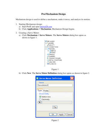
Pro/Mechanism DesignMechanism design is used to define a mechanism, make it move, and analyze its motion.1. Starting Mechanism design:a) Start Pro/E and open tutorial2b.asmb) Click Applications Mechanism. Mechanism Design begins.2. Creating a Servo Motor:a) Click Mechanism Servo Motors. The Servo Motors dialog box opens asshown in figure 1.Figure 1b) Click New. The Servo Motor Definition dialog box opens as shown in figure 2.Figure 2
c) On the Type tab, for the Driven Entity, select Motion Axis, and choose the pinjoint connecting part1.prt to part2.prt (connection 2 axis 1) as shown in figure3a.d) On the Profile tab, change the Specification to Velocity as shown in figure 3b.e) The Magnitude should be Constant. Enter the value 72 for A as shown in figure3b.Figure 3aFigure 3bf) Select the Position check box and click. The plot shows that the servo motorwill go through two full rotations in 10 seconds as shown in figure 4.Figure 4g) Click OK.
3. Creating and Running a Kinematic Analysisa) Select Analysis Mechanism Analysis or click. The Analysis Definitiondialog box opens as shown in figure 5a.Figure 5aFigure 5bb) Under Type, select Kinematic. Accept the default name, AnalysisDefinition1.c) On the Preferences tab, accept the default values.d) On the Motors tab, be sure ServoMotor1 is listed. If it is not, clickin figure 5b.as showne) Click Run. The progress of the analysis is shown at the bottom of the modelwindow, and the model moves through the specified motion.To view the analysis results in later sessions of Mechanism design, you must savethem as a playback file.4. Saving and Reviewing Resultsa) Replay results. Select Analysis Playback or click. The Playbacks dialogbox opens as shown in figure 6a, click. The Animate dialog box opens asshown in figure 6b.
Figure 6ab) ClickFigure 6bto play or click Capture to save animation file as shown in figure 7.Figure 7c) On the Playbacks dialog box, clickto save your results as a .pbk file. In theSave dialog box, accept the default name or change to another name. The defaultdirectory is the current working directory. You can also browse to find anotherdirectory to save your file. You can open the .pbk file in future sessions byclickingand selecting the playback file. Click Close to quit.
d) Select Analysis Measures or clickopens as shown in figure 8. The Measure Results dialog boxFigure 8Figure 9e) Click. The Measure Definition dialog box opens as shown in figure 9.Accept measure1 as the name.f) Under Type, select Position.g) Select a vertex on the part2 as shown in figure 10.Figure 10h) Select Y-component in the Component area, and accept the WCS for theCoordinate System. Under Evaluation Method, accept Each Time Step asshown in Figure 11.
Figure 11i) Click OK.j) On the Measure Results dialog box as shown in figure 12, select measure1 underMeasures, and AnalysisDefinition1 under Result Set. (If you changed the resultset name, select the appropriate name.) The Graph Type should be Measure vs.Time.Figure 12Figure 13k) Clickto see the plot of the measure. The plot should be a cosine curve asshown in figure 13.l) Click to view animated simulation Tutorial2c.mpg
Pro/Mechanism Design . Mechanism design is used to define a mechanism, make it move, and analyze its motion. 1. Starting Mechanism design: a) Start Pro/E and open tutorial2b.asm b) Click Applications Mechanism. Mechanism Design begins. 2. Creating a Servo Motor: a) Click Mechanism Servo Motors. The Servo Motors dialog box opens as