Transcription
Machine Automation Controller NJ-seriesEtherNet/IPTMConnection GuideOmron Adept Technologies,Inc.Adept Robot of ePLCIOP650-E1-01
About Intellectual Property Rights and TrademarksMicrosoft product screen shots reprinted with permission from Microsoft Corporation.Windows is a registered trademark of Microsoft Corporation in the USA and other countries.ODVA and EtherNet/IPTM are trademarks of ODVA.EtherCAT(R) is registered trademark and patented technology, licensed by Beckhoff AutomationGmbH, Germany.Sysmac is a trademark or registered trademark of OMRON Corporation in Japan and othercountries for OMRON factory automation products.Company names and product names in this document are the trademarks or registeredtrademarks of their respective companies.
Table of Contents1.Related Manuals . 12.Terms and Definitions . 33.Precautions . 54.Overview . 65.Applicable Devices and Device Configuration . 75.1. Applicable Devices . 75.2. Device Configuration . 86.EtherNet/IP Settings. 106.1. Parameters . 106.2. Global variables. 116.3. Tag Sets . 126.4. Tag Data Link Table . 127.EtherNet/IP Connection Procedure . 137.1. Work Flow . 137.2. Robot Controller Setup. 147.3. Controller Setup . 217.4. EtherNet/IP Communication Status Check . 368.Initialization method . 428.1. Initializing Controller . 429.Appendix: Procedure Using the Project File . 439.1. Work Flow . 439.2. Controller Setup . 4410. Revision History . 46
1.Related Manuals1. Related ManualsTo ensure system safety, make sure to always read and follow the information provided in allSafety Precautions and Precautions for Safe Use in the manuals for each device which isused in the system.The table below lists the manuals provided by Omron Adept Technologies, Inc. (hereinafterreferred to as OAT) and OMRON Corporation (hereinafter referred to as OMRON), whichpertain to this document.ManufacturerOMRONOMRONOMRONOMRONCat. No.W500W501W506W504ModelManual nameNJ501-[][][][]NJ-seriesNJ301-[][][][]CPU UnitNJ101-[][][][]Hardware User's ManualNJ501-[][][][]NJ/NX-seriesNJ301-[][][][]CPU UnitNJ101-[][][][]Software User's ManualNJ501-[][][][]NJ/NX-seriesNJ301-[][][][]CPU Unit Built-in EtherNet/IPTM PortNJ101-[][][][]User's ManualSYSMAC-SE2[][][]Sysmac Studio Version 1Operation ManualOMRON0969584-7W4S1-05[]Switching HubW4S1-03BW4S1-seriesUsers ManualMachineAutomationController NJ-seriesStartup GuideAdept Robot Control 592-ECobra350Cobra 350 Robot ePLCQuick Setup GuideOATI593-EeCobra 600/800/800eCobra 600, 800, and 800 InvertedRobots User's GuideInvertedOATI594-EeCobra 600/800/800InvertedRobot Safety GuideCobra 350 RobotUser's GuideeCobra 600, 800, and 800 InvertedRobots ePLC Quick Setup GuideOATI595-EHornet 565Hornet 565 RobotQucik Setup GuideOATI596-EHornet 565Hornet 565 RobotUser's GuideOATI597-EQuattroQuattro 650H/650HS/800H/800HSUser's Guide650H/650HS/800H/800HS1
1.Related ManualsManufacturerOATCat. No.I598-EModelManual name650H/650HS/800H/8Quattro 650H/650HS/800H/800HS ePLCQuick Setup GuideQuattro00HSOATI599-EViper 650/850eMB-60RViper 650/850 Robot with eMB-60RUser's GuideViper 650/850 ePLCQuick Setup GuideT20 PendantUser's GuideOATI600-EViper 650/850OATI601-ET20OATI602-ESmartController EXSmartController EXUser's GuideOATI603-EACEACEUser's Guide, v3.4.xOATI604-E-eV LanguageUser's Guide,OATI605-E-eV LanguageReference Guide,OATI606-E-eV OperatingSystem User's GuideOATI607-E-eV Operating SystemReference GuideOATI608-ESmartVision MXSmartVision MXUser's GuideOATI609-EACE SightACE SightReference Guide, v3.2.x2
2.Terms and Definitions2. Terms and DefinitionsTermOATExplanation and DefinitionOAT is an abbreviation of the company name Omron AdeptTechnologies, Inc.NodeControllers and devices are connected to an EtherNet/IP network viaEtherNet/IP ports. EtherNet/IP recognizes each EtherNet/IP portconnected to the network as one node.When a device with two EtherNet/IP ports is connected to theEtherNet/IP network, EtherNet/IP recognizes this device as two nodes.EtherNet/IP achieves the communications between controllers or thecommunications between controllers and devices by exchanging databetween these nodes connected to the network.TagA minimum unit of the data that is exchanged on the EtherNet/IP networkis called a tag. The tag is defined as a network variable or as a physicaladdress, and it is assigned to the memory area of each device.Tag setIn the EtherNet/IP network, a data unit that consists of two or more tagscan be exchanged. The data unit consisting of two or more tags for thedata exchange is called a tag set. Up to eight tags can be configured pertag set for OMRON controllers.Tag data linkIn EtherNet/IP, the tag and tag set can be exchanged cyclically betweennodes without using a user program.This standard feature on EtherNet/IP is called a tag data link.ConnectionA connection is used to exchange data as a unit within which dataconcurrency is maintained. The connection consists of tags or tag sets.Creating the concurrent tag data link between the specified nodes iscalled a "connection establishment". When the connection isestablished, the tags or tag sets that configure the connection areexchanged between the specified nodes concurrently.There are two ways to specify the connection: one is to specify a tag setname (tag name), and the other is to specify an instance number ofAssembly Object.Connection typeThere are two kinds of connection types for the tag data link connection.One is a multi-cast connection, and the other is a unicast (point-to-point)connection. The multi-cast connection sends an output tag set in onepacket to multiple nodes. The unicast connection separately sends oneoutput tag set to each node. Therefore, multi-cast connections candecrease the communications load if one output tag set is sent tomultiple nodes.3
2.Terms and DefinitionsTermExplanation and DefinitionOriginator andTo operate tag data links, one node requests the opening of aTargetcommunications line called a "connection".The node that requests to open the connection is called an "originator",and the node that receives the request is called a "target".Each communication data is called an ''originator variable'' and a ''targetvariable''.In Sysmac Studio, the instance number is specified in the target variable.Tag data linkA tag data link parameter is the setting data to operate tag data links.parameterIt includes the data to set tags, tag sets, and connections.EDS fileA file that describes the number of I/O points for the EtherNet/IP deviceand the parameters that can be set via EtherNet/IP.4
3.Precautions3. Precautions(1) Understand the specifications of devices which are used in the system. Allow somemargin for ratings and performance. Provide safety measures, such as installing a safetycircuit, in order to ensure safety and minimize the risk of abnormal occurrence.(2) To ensure system safety, make sure to always read and follow the information providedin all Safety Precautions and Precautions for Safe Use in the manuals for each devicewhich is used in the system.(3) The user is encouraged to confirm the standards and regulations that the system mustconform to.(4) It is prohibited to copy, to reproduce, and to distribute a part or the whole of thisdocument without the permission of OMRON Corporation.(5) The information contained in this document is current as of April 2016. It is subject tochange for improvement without notice.The following notations are used in this document.Indicates a potentially hazardous situation which, if not avoided,may result in minor or moderate injury, or may result in seriousinjury or death. Additionally there may be significant propertydamage.Indicates a potentially hazardous situation which, if not avoided,may result in minor or moderate injury or property damage.Precautions for Correct UsePrecautions on what to do and what not to do to ensure proper operation and performance.Additional InformationAdditional information to read as required.This information is provided to increase understanding or make operation easier.SymbolThe filled circle symbol indicates operations that you must do.The specific operation is shown in the circle and explained in the text.This example shows a general precaution for something that you mustdo.5
4.Overview4. OverviewThis document describes the procedures for connecting OAT Adept Robot (hereinafterreferred to as Robot Controller) to OMRON NJ Series Machine Automation Controller(hereinafter referred to as Controller) via EtherNet/IP and for checking their connections.Refer to Section 6. EtherNet/IP Settings and Section 7. EtherNet/IP Connection Procedure tounderstand setting methods and key points to operate the EtherNet/IP tag data links.Additional InformationSettings described in 7.3. Controller Setup are set in advance in the Sysmac Studio projectfile (hereinafter referred to as project file) listed below. Refer to Section 9. Appendix:Procedure Using the Project File for information on how to use the project file.Obtain a latest project file from OMRON.NameSysmac Studio project file(extension: csm2)File nameOMRON ePLCIO EIP EV100.csm2VersionVer.1.006
5.Applicable Devices and Device Configuration5. Applicable Devices and Device Configuration5.1. Applicable DevicesThe applicable devices are as follows:ManufacturerOMRONNameNJ-series CPU UnitOATRobot ra350eCobra 600/800/800 InvertedHornet565Quattro 650H/650HS/800H/800HSViper 650/850Precautions for Correct UseIn this document, the devices with models and versions listed in 5.2. Device Configuration areused as examples of applicable devices to describe the procedures for connecting thedevices and checking their connections.You cannot use devices with versions lower than the versions listed in 5.2.To use the above devices with models not listed in 5.2. or versions higher than those listed in5.2., check the differences in the specifications by referring to the manuals before operatingthe devices.Additional InformationThis document describes the procedures for establishing the network connections.It does not provide information on operation, installation, wiring method, device functionality,or device operation, which is not related to the connection procedures.Refer to the manuals or contact Omron Adept Technologies, Inc.Additional InformationContact Omron Adept Technologies, Inc. for robots connectable to Robot Controller.7
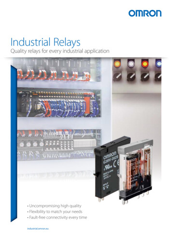
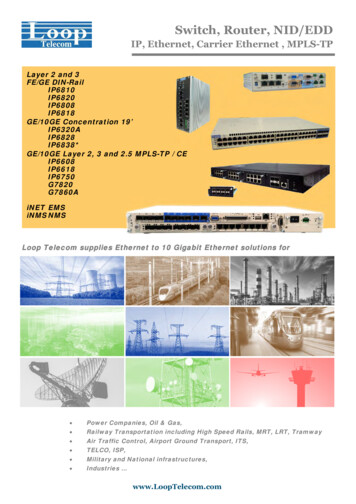
5.Applicable Devices and Device Configuration5.2. Device ConfigurationThe hardware components to reproduce the connection procedures in this document are asfollows:T20T20 adapter cablePersonal computer(Sysmac Studio andACE installed,OS: Windows 7)NJ501-1500(Built-in EtherNet/IP port)W4S1-05CLAN cableUSB cableLAN cableManufacturerOMRONeCobra S600eAIB ( eV)eAIBXSYSTEMcable24 VDC power supply(for Robot Controller)24 VDC power supplyNameNJ-series CPU Unit(Built-in EtherNet/IP port)Power Supply UnitSwitching hub24 VDC power 05C-Ver.1.0SYSMAC-SE2[][][]ACE-OATOATSysmac StudioACEPersonal computer (OS: Windows 7)USB cable(USB 2.0 type B connector)LAN cable (STP (shielded,twisted-pair) cable of Ethernetcategory 5 or higher)RobotRobot ControllerOATeAIB XSYSTEM cable(Supplied with Robot)OATXUSR jumper plug(Supplied with Robot)OATFront panel jumper plug(Supplied with Robot)OATT20 adapter cable(Supplied with Robot)OATXBELTIO jack(Supplied with Robot)OATTeaching PendantT20OAT24 VDC power supply-OMRONOMRONOMRONOMRON-(for Switching hub)Ver.1.15Ver.3.6.3.50eCobra S600eAIB ( eV)V2.3.C1(for Robot Controller)8
5.Applicable Devices and Device ConfigurationPrecautions for Correct UseUpdate Sysmac Studio to the version specified in this Clause 5.2. or to a higher version.If you use a version higher than the one specified, the procedures and related screenshotsdescribed in Section 7. and subsequent sections may not be applicable. In that case, use theequivalent procedures described in this document by referring to the Sysmac Studio Version1 Operation Manual (Cat. No. W504).Additional InformationFor specifications of 24 VDC power supply available for Switching hub, refer to the SwitchingHub W4S1-series Users Manual (Cat. No. 0969584-7).Additional InformationFor specifications of 24 VDC power supply available for Robot Controller, refer to the eCobra600, 800, and 800 Inverted Robots User’s Guide (Cat. No. I593-E).Additional InformationThe system configuration in this document uses USB for the connection between Personalcomputer and Controller. For information on how to install the USB driver, refer to A-1 DriverInstallation for Direct USB Cable Connection in Appendices of the Sysmac Studio Version 1Operation Manual (Cat. No. W504).9
6.EtherNet/IP Settings6. EtherNet/IP SettingsThis section describes the setting contents of parameters, global variables, tag sets, and tagdata link table that are all defined in this document.6.1. ParametersThe parameters that are set in this document are shown below.6.1.1.Communication Settings of Personal ComputerThe parameters for Robot Controller are set on Personal computer for setting via an Ethernetnetwork.The parameters required for connecting Personal computer for setting and Robot Controllerusing the Ethernet communications are shown below.ItemPersonal computerRobot Controllerfor settingIP address172.16.127.10*2172.16.127.103 (Default) *1Subnet mask255.255.0.0255.255.0.0 (Default)*1. Each Robot Controller is allocated with a unique IP address.Set an IP address of Personal computer for setting according to an IP address of RobotController. This IP address provided above is for Robot Controller used in this document.*2. Set an IP address of Personal computer for setting, which needs to have a different hostpart of an IP address from the one of Robot Controller.6.1.2.EtherNet/IP Communications SettingsThe parameters required for connecting Controller to Robot Controller via EtherNet/IP areshown below.ItemControllerRobot ControllerIP address192.168.250.1192.168.250.2Subnet mask255.255.255.0255.255.255.010
6.EtherNet/IP Settings6.2.Global variablesThe Controller treats the data in tag data links as global variables.The contents of global variable settings are shown below.NameData typeNetworkRobot Controllerpublishdata assignmentto RobotBYTE[488]Outputfrom RobotBYTE[488]Input Robot Controller input/output areaControllerGlobal variableArray No.[0]・・・[479]to Robot[480]・・・[487][0]・・・[479]from Robot[480]・・・[487]Data size(byte)Input area488Output area488Robot Controller480 bytesDIGITAL INPUT 1641 to 1704 (64 points)480 bytesDIGITAL OUTPUT 0641 to 0704 (64 points)Precautions for Correct UseIf the data size of the tag data link for Robot Controller is an odd-numbered byte, use BYTEtype to define, do not use BOOL type.Additional InformationWith Sysmac Studio, two methods can be used to specify an array for a data type.After specifying, (1) is converted to (2), and the data type is always displayed as (2).(1)BOOL[16] / (2)ARRAY[0.15] OF BOOLIn this document, the data type is simplified by displaying BOOL[16].(The example above means a BOOL data type with sixteen array elements.)11
6.EtherNet/IP Settings6.3. Tag SetsThe contents of tag set settings to operate tag data links are shown below. Output area (Controller to Robot Controller)Originator variable (Tag set name)Data size (byte)EIP002 OUTOUT No.1488Global variable name (tag name)Data size (byte)to Robot488 Input area (Robot Controller to Controller)Originator variable (Tag set name)Data size (byte)EIP002 ININ No.1488Global variable name (tag name)Data size (byte)from Robot4886.4. Tag Data Link TableThe contents of tag data link table settings (connection settings) are shown below.The values marked with red squares are taken from the values defined in the EDS file forRobot Controller.ConnectionNameConnection I/O TypeRPI (ms)Timeout Valuedefault 001Robot Command/Response50.0RPI x 4ConnectionI/O TypeRobotCommand/ResponseInput /OutputTarget Variable(RobotController setvalue: instancenumber)Size(Byte)Originator Variable(Tag set name)Size(Byte)Input5488EIP002 IN488Output6488EIP002 OUT488ConnectionTypeMulti-castconnectionPoint toPointconnection12
7.EtherNet/IP Connection Procedure7. EtherNet/IP Connection ProcedureThis section describes the procedures for connecting Robot Controller and Controller on theEtherNet/IP network. The explanation of procedure for setting up Controller given in thisdocument is based on the factory default settings.For the initialization, refer to Section 8. Initialization Method.7.1. Work FlowTake the following steps to operate tag data links by connecting Robot Controller andController via EtherNet/IP.7.2. Robot Controller SetupSet up Robot Controller. 7.2.1. Cable ConnectionConnect cables to Robot Controller. 7.2.2. IP Address SettingsSet the IP address of Robot Controller. 7.3. Controller SetupSet up Controller. 7.3.1. IP Address SettingsStart Sysmac Studio and set the IP address ofController. 7.3.2. Target Device RegistrationRegister the target device. 7.3.3. Setting the Global VariablesSet the global variables to use for tag data links. 7.3.4. Tag RegistrationRegister the tags and the tag sets. 7.3.5. Setting the ConnectionsSet the target variables and the originatorvariables, and then set the connections. 7.3.6. Transferring the Project DataConnect online and transfer the connectionsettings and the project data to Controller. 7.4. EtherNet/IP Communication StatusCheckConfirm that the EtherNet/IP tag data links areoperated normally. 7.4.1. Checking the Connection StatusCheck the connection status of the EtherNet/IPnetwork. 7.4.2. Checking the Sent andCheck that the correct data are sent and received.Received Data13
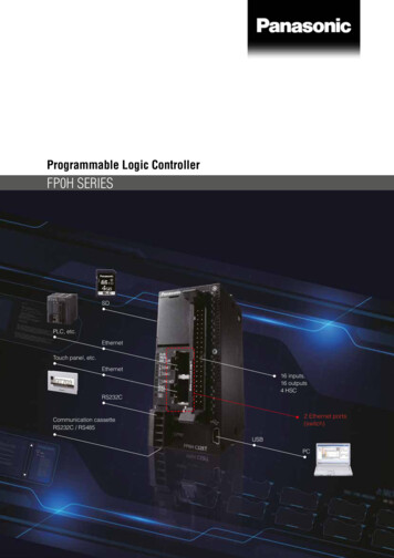
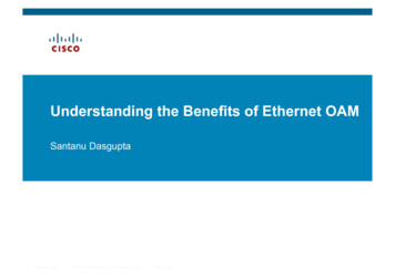
7.EtherNet/IP Connection Procedure7.2. Robot Controller SetupSet up Robot Controller.7.2.1.Cable ConnectionConnect cables to Robot Controller.Precautions for Correct UseMake sure that the power supply is OFF when you set up.12Make sure that Robot Controlleris powered OFF.*If the power supply is turnedON, the settings described inthe following steps andsubsequent procedures maynot be applicable.Check the position of RobotController by referring to thefigure on the right.RobotController3Status PanelCheck the position of theconnectors on Robot Controllerby referring to the figure on rts24VDC Inputconnector200-240VACXIOconnectorXBELTIOPort14
7.EtherNet/IP Connection Procedure4Plug XBELTIO jack into theXBELTIO port.XBELTIO jack5Connect an eAIB XSYSTEMcable to the XSYSTEMeAIB XSYSTEM cableconnector.6Connect the eAIB XSYSTEMcable and Teaching Pendantwith a T20 adapter cable.T20 adapter cableeAIB XSYSTEMcableConnect XUSR jumper plug toone branch of the eAIBXUSR jumper plugXSYSTEM cable.Connect Front panel jumperplug to the other branch of theFront panel jumper plugeAIB XSYSTEM cable.7Connect Ethernet Port (on theright) to Switching hub with aLAN cable.Connect Switching hub toPersonal computer with a LANLAN cablecable.8Connect 24 VDC power supply(for Switching hub) to Switchinghub.9Connect 24 VDC power supply(for Robot Controller) to the 24VDC Input connector.1024 VDC power supply(for Switching hub)24 VDC power supply(for Robot Controller)Connect 200 VAC power supplyto 200-240VAC.200 VAC power supply15
7.EtherNet/IP Connection Procedure7.2.2.IP Address SettingsSet the IP address of Robot Controller.The IP Addresses are set using ACE.Install ACE on Personal computer beforehand.For information on how to install the software, refer to the ACE User's Guide, v3.4.x (Cat. No.I603-E).Since the Personal computer and Robot Controller are connected via Ethernet, set the IPaddress of Personal computer to 172.16.127.10.Precautions for Correct UseThe Parameters for Robot Controller are checked using the Ethernet communications withPersonal computer.Note that there may be some changes required for the Personal computer settingsdepending on the state of Personal computer.1Turn ON Personal computer,Switching hub, and RobotController.16
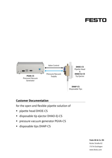
7.EtherNet/IP Connection Procedure2Set the IP address of PersonalDialog box in (2)computer to 172.16.127.10.*The IP address can bechanged in the following way.(1)Start Personal computer andlog in using an administratoraccount. From the WindowsStart menu, select ControlPanel - Network andInternet - Network andSharing Center, and clickChange Adapter Settings.Double-click Local AreaConnection.*The procedure steps may bedifferent depending on theenvironment settings ofPersonal computer.Dialog box in (3)(2)The Local Area ConnectionStatus Dialog Box isdisplayed. Click Properties.(3)The Local Area ConnectionProperties Dialog Box isdisplayed. Select InternetProtocol Version 4(TCP/IPv4), and clickProperties.*The display differs dependingon the configuration ofPersonal computer.(4)The Internet Protocol Version4 (TCP/IPv4) PropertiesDialog Box is displayed.Select Use the following IPaddress, set the IP address to172.16.127.10 and the subnetmask to 255.255.0.0.Click OK.Dialog box in (4)(5)Click Close or OK to close allthe displayed dialog boxes.17
7.EtherNet/IP Connection ProcedurePrecautions for Correct UseIf you change the IP address and the subnet mask during the operation of Robot, thechanged addresses are applied after power cycling Robot and Robot Controller.3Start ACE on Personal4ACE starts.computer.Select Connect To Controller inthe Getting Started Dialog Box.5The IP address of RobotController (172.16.127.103 inthis example) is displayed in theSelected Controller IP Addressfor Connect To Controller.Click(Detect and ConfigureAdept Controller).18
7.EtherNet/IP Connection Procedure6The Controller IP AddressDetection And ConfigurationWindow is displayed.Select the IP address of RobotController (172.16.127.103 inthis example) displayed in theControllers Detected Field.7Set the following parameters inthe Desired Properties Field.Desired Address:192.168.250.2Desired Subnet:255.255.255.0Click OK.8A confirmation dialog box isdisplayed. Check the contentsand click OK.19
7.EtherNet/IP Connection Procedure9The Waiting for Controller toReset Dialog Box is displayed.After more than 40 seconds areelapsed, clickto close thedialog box.10Click(refresh) and checkthat the displayed IP address issame as the one set in step 7.11Click Cancel to close the12Select Exit from the File Menu13Turn OFF Switching hub.Getting Started Dialog Box.to close ACE.20
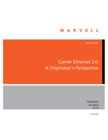
7.EtherNet/IP Connection Procedure7.3. Controller SetupSet up Controller.7.3.1.IP Address SettingsStart Sysmac Studio and set the IP addresses of Controller.Install Sysmac Studio and the USB driver on Personal computer beforehand.1Connect the LAN cable to thebuilt-in EtherNet/IP portPersonalcomputer(PORT1) on Controller, andconnect a USB cable to theCPU UnitControllerConfiguration, connect PersonalSwitching hubUSB cableperipheral (USB) port.As shown in 5.2. DeviceEnd CoverPower Supply UnitLAN cableRobotControllercomputer and Switching hub toController.23Start Sysmac Studio.*If the User Account ControlDialog Box is displayed at start,make a selection to startSysmac Studio.Sysmac Studio starts.Click New Project.21
7.EtherNet/IP Connection Procedure4The Project Properties DialogBox is displayed.*In this document, New Projectis used as the project name.Check that the device used isshown in the Category and theDevice Fields of Select Device.Select an applicable versionfrom the pull-down list ofVersion.56*Although 1.11 is selected in thisdocument as an example,select the version you actuallyuse.Click Create.The New Project is displayed.The following panes aredisplayed in this window.ToolboxLeft: Multiview ExplorerTop right: ToolboxBottom right: Controller Status PaneMiddle top: Edit PaneMultiviewExplorerEdit PaneControllerstatusPaneThe following tab pages aredisplayed at the middle bottomof the window.Output Tab PageBuild Tab PageOutput TabPageBuild TabPage22
7.EtherNet/IP Connection Procedure7Double-click Built-inEtherNet/IP Port Settingsunder Configurations andSetup - Controller Setup in theMultiview Explorer.8The Built-in EtherNet/IP PortSettings Tab Page is displayedin the Edit Pane.Check that the following settingsare made in the IP AddressField.IP address: 192.168.250.1Subnet mask: 255.255.255.023
7.EtherNet/IP Connection Procedure7.3.2.Target Device RegistrationRegister the target device.1Select EtherNet/IP Connection2The EtherNet/IP Device List TabSettings from the Tools Menu.Page is displayed in the EditPane.Right-click Built-in EtherNet/IPPort Settings and select Editfrom the menu.3The Built-in EtherNet/IP PortSettings Connection SettingsTab Page is displayed in theEdit Pane.4Click the Button in theToolbox.24
7.EtherNet/IP Connection Procedure5Data fields of the target deviceregistration are displayed.Enter 192.168.250.2 in the Nodeaddress Field.Select the following values fromthe pull-down lists of Modelname and Revision.Model name: Omron AdeptRobot ControllerRevision: 16Check the settings and click7192.168.250.2 is registered inAdd.Target Device of the Toolbox.25
7.EtherNet/IP Connection Procedure7.3.3.Setting the Global VariablesSet the global variables to use for tag data links.1Double-click Global Variablesunder Programming - Data inthe Multiview Explorer.2The Global Variables Tab Pageis displayed in the Edit Pane.Click the Name entry cell for thecolumn to enter a new variable.Enter to Robot in the NameColumn.Enter BYTE[488] in the DataType Column.After entering, check that thedata type changes toARRAY[0.487] OF BYTE.Select Output from thepull-down list of NetworkPublish.3After entering, right-click andselect Create New from themenu.4In the same way as step 2, enterthe following data in the newlyadded row.Name: from RobotData Type: BYTE[488]Network Publish: Input26
7.EtherNet/IP Connection Procedure5Double-click Task Settingsunder Configurations andSetup in the Multiview Explorer.The Task Settings Tab Page isdisplayed in the Edit Pane.Click VAR.6Click the Button.A row for new entry is added.Click the Down Arrow Button ofthe entry cell in the Variable tobe refreshed Column (the leftside of the figure).The variables set in the previoussteps are displayed.Select to Robot.to Robot is added.7*Since the data types aredisplayed automatically, you donot need to set them.In the same way as step 6, addall the variables that you set inthis procedure to the Variable tobe refreshed Column (the leftside of the figure).*Since the data types aredisplayed automatically, you donot need to set them.27
7.EtherNet/IP Connection Procedure7.3.4.Tag RegistrationRegister the tags and the tag sets.1Click the Tag Set Button on theBuilt-in EtherNet/IP PortSettings Connection SettingsTab Page.Select the Input Tab in TagSets.2Right-click any open space onthe Input Tab Page and selectCreate New Tag Set from themenu.3A new tag name can be entered.Select the newly added entrycell.Enter EIP002 IN.4Right-click EIP002 IN andselect Create New Tag from themenu.A new tag name can be enteredunder EIP002 IN. Select thenewly added entry cell.Set the global variable for inputlisted in 6.3. Tag Sets.*When the first character of theset variable name is typed, anappropriate name beginningwith the character appears asshown on the right.5Select Output Tab.Right-click any open space onthe Output Tab Page and selectCreate New Tag Set from themenu.28
7.EtherNet/IP Connection Procedure6A new name can be entered inthe Tag Set Name Column.In the same way as step 3, enterEIP002 OUT.7In the same way as step 4, setthe global variable for output asa tag, which is listed in 6.3. TagSets.8Check that Tag Sets shows 2and that the number of Tagsshows the same as the numberof the global variables you set.29
7.EtherNet/IP Connection Procedure7.3.5.Setting the ConnectionsSet the target variables (that receive the open request) and the originator variables (thatrequest for opening), and then set the connections (tag data link table).1Click the Connection Button onthe Built-in EtherNet/IP PortSettings Connection SettingsTab Page.2Right-click any open space
The table below lists the manuals provided by Omron Adept Technologies, Inc. (hereinafter referred to as OAT) and OMRON Corporation (hereinafter referred to as OMRON), which . OMRON ACE ACE Ver.3.6.3.50 - Personal computer (OS: Windows 7) - - USB cable (USB 2.0 type B connector) - - LAN cable (STP (shielded, twisted-pair) cable of Ethernet .