Transcription
Feed Modules VKKThe Drive & Control Company
2Bosch Rexroth CorporationFeed Modules VKKR310A 2403 (2008.09)Linear Motion and Assembly TechnologiesBall Rail SystemsRoller Rail SystemsLinear Bushings and ShaftsBall Screw DrivesLinear Motion SystemsBasic Mechanical ElementsManual Production SystemsTransfer Systemswww.boschrexroth-us.com
R310A 2403 (2008.09)Feed Modules VKKBosch Rexroth CorporationFeed Modules VKKProduct Description4Product Overview6Motor selection based on drive controllersand control system6Overview of types with load capacities8Dimensions9Structural Design10Feed Module VKK10Attachments10Motor mount and coupling11Timing belt side drive11Technical Data12Calculations16Feed Module VKK 15-7018Components and Ordering Data18Dimension Drawings20Feed Module VKK 25-10022Components and Ordering Data22Dimension Drawings24Switch Mounting ArrangementsMotorsAC servo motors MSK262828AC servo motors MSM293-phase stepping motors VRDM30Mounting31Mounting Accessories32Mounting to Installed Modules34Connection Elements35Standard flange35Connection of Gripper GSP36Connection of Rotary Compact Module RCM37Lubrication38Documentation39Ordering Example41Notes42Inquiry/Order Form433
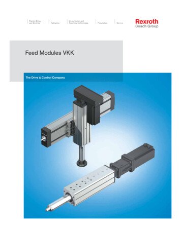
4Bosch Rexroth CorporationFeed Modules VKKR310A 2403 (2008.09)Product DescriptionOutstanding featuresFurther highlightsRexroth Feed Modules VKK are precise, ready-to-install linearmotion systems that combine high performance with compactdimensions. They are especially suitable for handling tasksrequiring high precision as well as high thrust and torquetransfer capabilities. Because of their low moved mass, FeedModules VKK are ideal for vertical motion in Z-axes.– Optimal travel performance, high load capacities and highrigidity due to integrated, zero-clearance ball rail system– Especially compact design due to integrated ball screw drive– Ball screw drive with zero-backlash nut system assures highpositioning accuracy and repeatability– Low-cost maintenance provided by one-point lubrication(grease) of the ball rail system and the ball screw drive– Easy motor attachment due to locating feature and fasteningthreads– Enclosed guideway– Switches can be positioned anywhere along the travel range– Switch activation without switching cam– Easy installation of various attachments– Fully compatible with the camoLINE system– Positive-locking connection technology with centering ringsRexroth offers favorable price/performance ratios and fastdelivery.Structural design– Extremely compact extruded aluminum profile (frame)with Ball Rail System in eLINE technology– Precision Ball Screw Drive in tolerance grade 7 withzero-backlash nut system– Fixed bearing end block made of aluminum with two-row,preloaded angular-contact thrust ball bearingAttachments– Maintenance-free digital AC servo drives with integratedbrake and attached feedback, or stepping motors– Motor mount and coupling or timing belt side drive formotor attachment– SwitchesDrive controllers and control systemsEnd block with threads and locating featurefor motor attachmentThrust rod with mounting interface for standard flange
R310A 2403 (2008.09)Feed Modules VKKBosch Rexroth Corporation5Motor attachment viatiming belt side driveMotor attachment viamotor mount and couplingFeed Module VKK 25-100Centering holes for positive-locking connections with goodrepeatability to simplify installation(camoLINE Cartesian Motion building system)Thrust rod with standard flange for a variety of attachments
6Feed Modules VKKBosch Rexroth CorporationR310A 2403 (2008.09)Product OverviewMotor selection based on drivecontrollers and control systemDigital AC servo motors MSKSeveral motor-controller combinationsare available in order to provide themost cost-effective solution for everycustomer application.When sizing the drive unit, always consider the motor-controller combination.Digital controllersIndraDriveRefer to the “Controllers, ElectricalAccessories” catalogs for more information about motors and control systems.Digital AC servo motors MSMDigital controllersECODRIVE CsPower electronics3-phase stepping motorsSD326SD328Profi Stepcontrol unitHandAutoRS232
R310A 2403 (2008.09)Feed Modules VKKBosch Rexroth CorporationFeed Modules VKK are available as complete solutions with motor and controller.7
8Feed Modules VKKBosch Rexroth CorporationR310A 2403 (2008.09)Product OverviewType designation (size)TypeVKExample: Feed ModuleFeed Module (V)Integrated Ball Rail System (K)Ball Screw (K)Width of frame (mm)Example: B 100 mmSystemGuidewayDrive unitFrame sizeSize25-100KBFeed Modules VKK are identified bythe type designation and size.DescriptionBOverview of types with load capacitiesTypeSystemGuidewayDrive unitSizeLoad capacitiesCCCCC (N)VKKFeed ModuleBall rail systemBall screw drive15-7025-100812026000
R310A 2403 (2008.09)Feed Modules VKK9Bosch Rexroth CorporationDimensionsBLBStandard lengths LFeed ModuleBmmLmmVKK 15-7070280320400520600VKK 25-100100360400480600680Stroke80120200320400
10Feed Modules VKKBosch Rexroth CorporationR310A 2403 (2008.09)Structural DesignFeed Module VKK1234565Ball screw with zero-backlash cylindrical single nutFixed bearing end blockFrameThrust rodMounting interface for standardflangeEnd seal432Attachments78910Magnetic field sensorMotorMotor mount and couplingTiming belt side drive1745698108
R310A 2403 (2008.09)Feed Modules VKKBosch Rexroth CorporationMotor mount and couplingA motor can be attached to all FeedModules by means of a motor mountand coupling.The motor mount serves to fasten themotor to the Feed Module and actsas a closed housing for the coupling.The motor’s drive torque is transmittedbacklash-free through the coupling tothe Feed Module's screw shaft.1Timing belt side driveAll Feed Modules offer the option ofattaching the motor via a side drive withtiming belt.This results in a shorter overall lengthcompared to a motor attachment viamotor mount and coupling.The compact, closed housing protectsthe belt and secures the motor. Variousgear ratios are also available:– i 1:1– i 1 : 1.5– i 1:2The timing belt side drive can bemounted in four different directions:– below, above (RV01 and RV02)– left, right (RV03 and RV04)MotorMotor mountCouplingFixed bearing end blockFeed ModuleEnd coverExtruded, anodized aluminum profileToothed beltPre-tensioning of the toothed belt:apply pretensioning force Fv to motor(Fv will be indicated on delivery)10 Belt pulleys11 Cover plate1234567892634545789Fv61011111
12Feed Modules VKKBosch Rexroth CorporationR310A 2403 (2008.09)Technical DataLoad capacities and momentsFeed ModuleBallscrewDynamic load capacity CDynamicmomentsPlanar moment of inertiazThrust rodyVKK 15-70VKK 25-100d0 x P16 x 516 x 1016 x 1620 x 525 x 1020 x 20Guideway(N)8 12026 000Ballscrew(N)12 3009 6006 30014 30015 70013 300Maximum permissible loadsMaximumstrokeMoved massof systemyFixedbearing(N)Mt(Nm)ML(Nm)13 4001602805.76.74001.317 9006701 30012.916.24002.5FeedModuleVKK 15-70VKK 25-100ly(cm4)zlz(cm4)Maximum permissible forcesmb(kg)Maximum permissible momentsFy max(N)3 25010 400Fz max(N)3 25010 400Hmax(mm)Mt max(Nm)55100M L max(Nm)110360Acceptable loads(recommended from experience)As far as the desired service life is concerned, loads of up to approximately20% of the dynamic load and momentvalues (C, Mt, M L) have proved acceptable.The following limits should not beexceeded:– maximum permissible loads– permissible drive torque– permissible travel speedNote on dynamic load capacitiesand momentsDetermination of the dynamic loadcapacities and moments is based ona travel life of 100,000 m. Often only50,000 m are actually stipulated.For comparison:Multiply values C, Mt and M L from thetable by 1.26.Permissible drive torque MpermRequirement:No radial load on ball screw shaftConsider the rated torque of thecoupling used!Permissible travel speed vConsider the motor speed!Feed ModuleVKK 15-70VKK 25-100Ball screwd0 x P16 x 516 x 1016 x 1620 x 525 x 1020 x 20Mperm(Nm)2.23.74.710.812.325.5Mperm with keyway(Nm)2.23.23.210.811.311.3Modulus of elasticity EE 70,000 N/mm2Weight of Feed Modulewithout motorVKK 15-70: 2.8 kg 0.0075 (kg/mm) . stroke (mm)VKK 25-100: 7.2 kg 0.0143 (kg/mm) . stroke (mm)Travel speed v(m/s)0.40.81.20.30.61.2
R310A 2403 (2008.09)Feed Modules VKKBosch Rexroth CorporationSpecifications of timing belt side drive for motor attachment via timing belt side driveMotorFrictional torque M RRV (Nm)Gear ratioFeed ModuleVKK 15-70VKK 25-100Ball screwd0 x P16 x 516 x 1016 x 1620 x 520 x 2025 x 10MotorFrictional torque M RRV (Nm)Gear ratioFeed ModuleVKK 15-70VKK 25-100Ball screwd0 x P16 x 516 x 1016 x 1620 x 520 x 2025 x 10MSM 030 C0.35Permissible torqueReduced mass momentup to length L atof inertia ati 1i 1.5i 1i 1.5M RvJ RvJ RvM Rv(Nm)(Nm)(10-6 kgm2) (10-6 �MSM 040B0.4Permissible torqueReduced mass momentup to length L atof inertia ati 1i 1.5i 1i 1.5M RvM RvJ RvJ Rv(Nm)(Nm)(10-6 kgm2) (10-6 .7MSK 030 C0.35Permissible torqueReduced mass momentup to length L atof inertia ati 1i 1.5i 1i 1.5M RvM RvJ RvJ Rv(Nm)(Nm)(10-6 kgm2) (10-6 �MSK 050 C0.45Permissible torqueReduced mass momentup to length L atof inertia ati 1i 2i 1i 2M RvM RvJ RvJ RvNmNm10-6 kgm210-6 kgm2––––––––10.85.41 42023015.07.512.36.2M RRv frictional torque of timing belt side drive at motor journal (Nm)M Rv permissible torque for system with timing belt side drive at motor journal (Nm);observe max. motor torque M MmaxJ Rv reduced mass moment of inertia of timing belt side drive (kgm2)i timing belt side drive reductionConstants k1, k2, k3Frictional torque M RFeed ModuleVKK 15-70VKK 25-100Coupling dataFeed ModuleThe couplings with the specificationsshown in the table are used with FeedModules VKK with standard servomotors.VKK 15-70VKK 25-100Ball screwd0 x P16 x 516 x 1016 x 1620 x 520 x 2025 x 10MotorattachmentMSM 030CMSM 040BMSK 030CMSK 040CVRDM 3910VRDM 3913MSM 040 BMSK 050CVRDM 31117k14.0354.3504.95839.34244.27346.551Rated 6.4850.0860.6330.24410.1320.1222.533Frictional torqueM R (Nm)0.330.340.370.520.670.69Coupling dataMass moment ofWeightinertia Jk(10-6 kgm2)(kg)19600.2619640.27502000.713
14Feed Modules VKKBosch Rexroth CorporationR310A 2403 (2008.09)Technical DataRigidity of thrust rodFeed Module VKK 15-70Rigidity in y-directionMeasured 1015202530354045M (Nm)Rigidity in z-direction21.81.6(mm)Gel elastic deflectionM torque(mm)Key to grapha Stroke 400 mmb Stroke 320 mmc Stroke 200 mmd Stroke 120 mme Stroke 80 mm1.41.2a1.0b0.80.6c0.4de0.200510152025303540M (Nm)45
R310A 2403 (2008.09)Feed Modules VKKRigidity of thrust rodFeed Module VKK 25-100Bosch Rexroth CorporationRigidity in y-directionMeasured 125150175200225M (Nm)Rigidity in z-direction54.54(mm)Gel elastic deflectionM torque(mm)Key to grapha Stroke 400 mmb Stroke 320 mmc Stroke 200 mmd Stroke 120 mme Stroke 80 mm3.53a2.52b1.5c1de0.500255075100125150175200M (Nm)22515
16Feed Modules VKKBosch Rexroth CorporationR310A 2403 (2008.09)CalculationsMaxM Lm FzaxFyMLmmaC xtmaxmaxFzmaFyxCmaxMxFeffT strokeMzMy(T strokeeff) center-to-center distance between runner blockand mounting interfaceTVKK15-70 124 mmTVKK25-100 166.5 mmCombined equivalent loadon bearing for guideway(1)FcombFyFzMxMyMzCMtMLFcomb Fy Fz C · Nominal life of guidewayin operating hours(3)CL Lh3Fcomb· 105 mL 3600 · vmFrictional torque(4)Motor attachment via motor mountand coupling:Motor attachment via timing beltside drive: C·Mtcombined equivalent load on bearingforce in y-directionforce in z-directionmoment about the x-axismoment about the y-axismoment about the z-axisdynamic load capacitydynamic torsional moment load capacitydynamic longitudinal moment load capacityNominal life of guideway(2)MxMRS MRRviMzML(N)(N)(N)(Nm)(Nm)(Nm)(N)(Nm)(Nm)LLhvm nominal life nominal life average speedMR frictional torque atmotor journal frictional torque of system frictional torque of timingbelt side drive at motorjournal gear ratioMR MRSMR ML C·L nominal lifeC dynamic load capacityFcomb combined equivalentload on bearingM RSM RRv(5)Myi(m)(N)(N)(m)(h)(m/s)(Nm)(Nm)(Nm)
R310A 2403 (2008.09)Feed Modules VKKBosch Rexroth Corporation17CalculationsMass moment of inertiaCondition for handling:6 · J M t JfrJMJfrCondition for processing:1.5 · J M ! JfrMotor attachment via motor mountand coupling:Jfr JS JK JBrJS (k1 k2 · L k3 · mfr) · 10-6JM JSJS JKJK JBrJBr JMJMJtotges JfrJfr JMJSJKJ BrJtotMotor attachment via timing beltside drive:Jfr JS JRv JBri2J RvJS (k1 k2 · L k3 · mfr) · 10-6JSJJtot JJfr JJM J2S JJRv JJBr JJMgesfrMRvBrMii 2Rotary speedn1 When attaching a gear motor, alsoinclude the gear mass moment of inertiaand gear reduction in the calculation.Conditions:n1 nmaxv vpermi · v · 1000PmfriLk1.k3n1nmaxPiv mass moment of inertiaof motor mass moment of inertiaof external load mass moment of inertia ofsystem with external load mass moment of inertiaof coupling mass moment of inertiaof motor brake total mass momentof inertia reduced mass momentof inertia of timing beltside drive at motor journal external load gear ratio length of Feed Module constants, see“Constants” )(mm) rotary speed(min–1) maximum usablemotor speed(min–1) screw lead(mm) gear ratio travel speed(m/min)(must be d vperm from“Permissible speed” chart)
18Bosch Rexroth CorporationFeed Modules VKKFeed Module VKK 15-70Components and Ordering DataGuidewayDrive unitScrew journalPart number, lengthR1462 300 00, . mmTypewith ball screw,without motor mountR310A 2403 (2008.09)Carriage (internal)Ball screw sized0 x ndardflange0102OF1Ø9OF01Ø9L 280 mm Keyway12111213Ø90102030102Ø90102030102MF01with ball screwand timing belt side drivewith ball screwand motor mountL 320 mm13MF01RV01RV03L 520 mm18RV02RV04L 400 mm15RV01toRV04L 600 mm20Order example: See “Inquiry/Order Form”cd0P screw diameter (mm) screw lead (mm)Please check whether the selected combination is a permissible one(load capacities, moments, maximum speeds, motor data, etc.)!For details of standard flange, see page 35.
R310A 2403 (2008.09)Feed Modules VKKMotor attachmentGear ratio Attachi ment kit 1)Bosch Rexroth CorporationMotor1st, 2nd, 3rd switchfor motorStandardreportwithout brake00i 1–00MSM 030C727302MSK 030C848503MSM 040B747504MSK 040C868711VRDM 3910394012VRDM 39134142MSM 030 C7273MSK 030C848523i 1.524i 121i 1.522Measurementreportwith brake01i 1DocumentationWithout switch00Switch (magnetic fieldsensor):– Reed sensor21– Hall sensor (PNP NC)221) Attachment kit also available without motor (when ordering: enter “00” for motor).Switch Mounting ArrangementsRefer to “Switch mounting arrangements” for more information on switch types and switch tioningaccuracy19
20Bosch Rexroth CorporationFeed Modules VKKFeed Module VKK 15-70R310A 2403 (2008.09)Dimension drawingsAll dimensions in mmDrawings not to scale30AØ19157.5AMax. travelExcess travelExcess travel9H7Ø40H7Ø9h7Ø20h7Effectivestroke2.538254N x 40 0.01132520L stroke 200Length ved mass of system6791214(kg)0.70.80.91.11.2Type OF01Excess travel(each side)Ball screw 16x5(mm)Ball screw 16x10(mm)2727272727Type MF01Ball screw 16x16(mm)Type RV01, RV02, RV03, RV04XED25DLRØ40H7Ø9h7K2.52.5 20LFGXF3P9LMh 1.8LM
R310A 2403 (2008.09)Bosch Rexroth Corporation2140287046M6 -14 deep4xFeed Modules VKK54702.1Ø9H7For sliding blocks/clamping fixtures(fastening on opposite side)T-slot for switchesB40TypeMSM 030CMSK 030CMSM 030CMSM 040BMSK 030CMSK 040CVRDM 3910VRDM 3913Ei on with standard –––––For details of standard flange,see page 35.455.214.5612Dimensions (mm)FGi 1 to 87217i 1179179––––––i 1.5191191––––––
22Bosch Rexroth CorporationFeed Modules VKKFeed Module VKK 25-100Components and Ordering DataGuidewaywith ball screw,without motor mountTypeØ 14Ball screw sized0 x hstandardflange0102Ø 14Keyway111213Ø 140102030102Ø 140102030102L 360 mm12with ball screwand motor mountMF01L 400 mm13L 480 mm15RV01RV03RV02RV04L 600 mm18RV01toRV04L 680 mm20Order example: See “Inquiry/Order Form”cCarriage (internal)OF1MF01with ball screwand timing belt side driveDrive unitScrew journalPart number, lengthR1462 400 00, . mmR310A 2403 (2008.09)d0P screw diameter (mm) screw lead (mm)Please check whether the selected combination is a permissible one(load capacities, moments, maximum speeds, motor data, etc.)!For details of standard flange, see page 35.
R310A 2403 (2008.09)Feed Modules VKKMotor attachmentGear ratio Attachi ment kit 1)Bosch Rexroth CorporationMotor1st, 2nd, 3rd switchStandardreportfor motorwithout brake00i 1–00MSM 040B747505MSK 050C888913VRDM 311174344Without switch00Switch (magnetic fieldsensor):– Reed sensor21– Hall sensor (PNP NC)222728i 129Measurementreportwith brake03i 1.5i 2DocumentationMSM 040B7475MSK 050C8889301) Attachment kit also available without motor (when ordering: enter “00” for motor).Switch Mounting ArrangementsRefer to “Switch mounting arrangements” for more information on switch types and switch tioningaccuracy23
24Bosch Rexroth CorporationFeed Modules VKKFeed Module VKK 25-100R310A 2403 (2008.09)Dimension drawings30AAll dimensions in mmDrawings not to scaleØ19157.5AMax. travelExcess travel12H7Excess travelØ55J6Ø14h7Ø20h7Effectivestroke4342N x 40 0.0160132520L stroke 280Length ved mass of system89111416(kg)1.51.61.82.02.2Type OF01Excess travel(each side)Ball screw 20x5(mm)Ball screw 25x10(mm)3939393939Type MF01Ball screw 20x20(mm)Type RV01, RV02, RV03, RV04X56020D42EDLRØ55 J6Ø14 h7K3LMLFXF5Gh 3LM
R310A 2403 (2008.09)Bosch Rexroth Corporation6650506610085M8 -18 deep8xFeed Modules VKK851002.1Ø12H7For sliding blocks/clamping fixtures(fastening on opposite side)T-slot for switches4.22.54.8B60TypeDMSM 040BMSK 050CMSM 040BMSK 050CVRDM 31117EDimensions (mm)FGi 1 i 1.5 i 8098110Version with standard For details of standard flange,see page 35.45Ø80MF015.214.516.58.1CMotorRV01 to ake––157.5203228LRwithbrake––191.5233281i 1231280–––i 1.5231––––i 2–280–––25
26Bosch Rexroth CorporationFeed Modules VKKR310A 2403 (2008.01)Switch Mounting ArrangementsOverview of switching systemSwitching system1 Switch (magnetic field sensor)2 T-slot for switch3 CableThe switch activator is a magnet integrated in the thrust rod.cFor short-stroke applications:Consider the length of the switch!21Magnetic field sensors with pottedcables can be used in the Feed Module.Type– Hall sensor (PNP NC) or– Reed sensor (changeover)Mounting instructionsThe magnetic field sensors (MFS) arepushed into the T-slot and fixed with setscrews.The MFS cables are routed along theside of the T-slot (3).For details regarding the switchingposition, see mounting instructions.2113
R310A 2403 (2008.01)Feed Modules VKKBosch Rexroth Corporation27Switch Mounting ArrangementsSwitch356.5Magnetic field sensor with potted cable635Active surfaceSet screw for fixingTechnical dataHall sensorContact typeOperating voltageCurrentconsumptionOutput currentCable lengthProtection classShort-circuitprotectionMax. travel speedPart numberPNP NC3.8–30 V DCmax. 10 mAmax. 20 mA2 m (10 m on request)IP 66Reed sensorContact typeSwitching voltageSwitching currentCable lengthProtection classMax. travel speedSwitching pointsPart numberChangeovermax. 100 V DCmax. 0.5 mA2 m (10 m on request)IP 662 m/s2R3476 018 03No2 m/sR3476 019 03Pin assignmentWhite: 3.8 . 30 V DCGreen:OutputReed sensorBrownHallsensorWhiteBrown: 0V groundGreen
28Bosch Rexroth CorporationFeed Modules VKKR310A 2403 (2008.01)MotorsAC servo motors MSK45NotesAll MSK motors have an absolute multiturn encoder.H2H1B3ØGAØEØDL1RAFB2B1ØThe motors can be supplied completewith controller and control unit. For moreinformation on motors, controllers andcontrol systems, see Rexroth catalog“Controllers . Servo Motors.”6032H3LDimensionsMotorMSK 030CMSK 040CMSK 5095ØFDimensions 143.5L w/obrake188185.5203L withbrake213215.5233L1R–42.555.5R5R8R8Motor dataMotorMaximum rotary speedMaximum permissible torqueRated torqueMotor mass moment of inertiaMass without brakeHolding brakeHolding torqueBrake mass moment of inertiaMass of brakenmaxMmaxMNJmmmUnitmin–1NmNm10–6 kgm2kgMSK 030C-0900900040.5302.1MSK 040C-060056008.12.71403.6MSK 050C-06005700155.03305.4MbrJbrmbrNm10–6 kgm2kg1.070.254.0230.325.01070.7
R310A 2403 (2008.01)Feed Modules VKKBosch Rexroth CorporationMotorsAC servo motors MSMNotesAll MSM motors have an absolute multiturn encoder.45H2H3The motors can be supplied completewith controller and control unit. For moreinformation on motors, controllers andcontrol systems, see Rexroth catalog“Controllers . Servo SM 030CMSM 040B6080B13035B233B378ØDh6Dimensions 576.0Lw/obrake138.5157.5Motor dataMotorMaximum rotary speedMaximum permissible torqueRated torqueMotor mass moment of inertiaMass without brakeHolding brakeHolding torqueBrake mass moment of inertiaMass of brakenmaxMmaxMNJmmmUnitmin–1NmNm10–6 kgm2kgMSM 030C30003.801.3017.01.5MSM 040B30007.102.4067.03.1MbrJbrmbrNm10–6 kgm2kg1.273.00.42.458.00.7withbrake171.5191.529
30Bosch Rexroth CorporationFeed Modules VKKR310A 2403 r connectorBrakeEncoder connectorBrake connectorØD h81234L 0.7–1B1A3-phase stepping motorsVRDM60 22.543213551R8.231B31925ØFDimensionsMotorAVRDM 3910VRDM 3913VRDM 19h6Dimensions (mm)ØDØF60h860h856h899.099.099.0ØG6.56.56.5Lw/o brake140.0170.0180.0with brake186.5216.5226.5Motor dataMotorMaximum permissible torqueRotor moment of inertia w/o brakeMotor holding torqueMass without brakeStep countStepping angle per stepEncoder resolutionHolding brakeBrake holding torqueBrake mass moment of inertiaMass of brakeSymbolMmaxJmMmmmzDUnitNmkgm2Nmkg– MbrJbrmbrNmkgm2kgVRDM 3910VRDM 3913VRDM 311174.006.0012.002.2 x 10–43.3 x 10–410.5 x 10–44.526.7813.923.14.28.0200 / 400 / 500 / 1000 / 2 000 / 4 000 / 5 000 / 10 0001.8 / 0.9 / 0.72 / 0.36 / 0.18 / 0.09 / 0.072 / 0.0361000 increments/revolution60.2 x 10–41.516.00.35 x 10–42.0
R310A 2403 (2008.01)Feed Modules VKKBosch Rexroth CorporationMountingGeneral notesFastening with clamping fixturesThe modules are mounted using clamping fixtures which engage in the T-slotson the side of the frame.Clamping fixturesSizeVKK 15-70VKK 25-100Dimensions (mm)AB86100116130A 0.1BMounting surfaceThe Feed Module may only be installed/connected to other modules by themounting surface with the centering holes.Centering holesMounting surfaceT-slot for switches31
32Bosch Rexroth CorporationFeed Modules VKKR310A 2403 (2008.01)Mounting AccessoriesClamping fixturesRecommended number of clampingfixtures:– Type 1: 4 pieces per side– Type 2: 2 pieces per side– Type 3: 1 piece per sideHBACACACBFCGEDCountersink forthread MISO 4762Number NType 1SizeForthreadTypeNumber of holesVKK 15-70M5VKK 15-70VKK 25-100M63313222N4414222Type 2Type 3Dimensions 504030D11.511.5E4.84.85.35.33.23.25.3Part numberF19.3G14H719.3147R0375 410 02R0375 410 26R0375 510 00R0375 510 02R0375 510 09R0375 510 11R0375 510 23
R310A 2403 (2008.01)Feed Modules VKKBosch Rexroth Corporation33Centering ringsDØFThe centering rings serve as a positioning aid. They create positive-lockingconnections with good reproducibility.DØFØCØAØB1 Feed Module2 Centering ring3 Customer’s attachment1ØCØAMaterial: steel (stainless)23EØASizeCenteringring sizeVKK 15-70VKK 25-100Ak69121216R0396 605 44R0396 605 50R0396 605 45R0396 605 51Bk6–9–12Dimensions (mm)CDE 0.1-0.2 0.26.64–6.64294–952ØF2222ASliding blocks and springsFor mounting attachments using theT-slots912-91216-12Part numberDCBMEMM1 ESizeVKK 15-70VKK 25-100Tightening torques of thefastening screwsat friction factor 0.125Strength class 8.88.8ForthreadM4M5M5M5M5M6M6Dimensions (mm)A6B11.5C4D181662Nmmax.E12451216161650Part numberM1–30––––36Sliding block3 842 523 140R0391 710 093 842 523 1423 842 514 9283 842 514 9293 842 514 930R0391 710 08Spring3 842 523 145–3 842 523 1453 842 516 6853 842 516 6853 842 516 685–M4M5M6M82.75.59.523
34Bosch Rexroth CorporationFeed Modules VKKR310A 2403 (2008.01)Mounting to Installed Modules– No intermediate plates required– Positive locking via centering rings(camoLINE compatible)– Easy mounting with clamping fixturesFeed Module VKK mounted to Compact Module CKKFeed Module VKK mounted to Bridge Module BKK
R310A 2403 (2008.01)Feed Modules VKKBosch Rexroth CorporationConnection ElementsStandard flangeFunction– Connection of customer attachmentsKit consisting of:1 Standard flange2 Set screw (2x M10x12, ISO 4026)2Note for orderingThe standard flange can ONLY beordered by specifying carriage option 02(carriage with standard flange).1Mounting instructionsThe standard flange is fastened to themounting interface on the thrust rod of theFeed Module using two M10 set screws.cIf the standard flange is removed,the set screws must be secured again(e.g. using a medium-strength, liquidthreadlocker adhesive) when it is reinstalled!Tightening torque for the set screws30 NmØ12H745152.1 deep060ISO 4026 – M10 x 12M4Ø7H7030Ø20H7Ø50Ø6Ø4Ø80M5Ø9 H7M61.6 deepCentering holes for centering rings35
36Bosch Rexroth CorporationFeed Modules VKKR310A 2403 (2008.01)Connection ElementsConnection of Gripper GSPFunction– Connection of Pneumatic Grippers,Type GSP (camoLINE range)5Kit consisting of:1 Connection plate2 Mounting screws3 Centering rings42Additional parts (not included in kit):4 Standard flange5 Set screws (M10x12, ISO 4026)6 Gripper GSP312Mounting instructionsThe standard flange (4) is required formounting of the connection plate. Pleaseorder this by specifying carriage option02 (carriage with standard flange). Fordetails and dimensions, see page 35.cIf the standard flange isremoved, it must be secured withthe set screws again when it isre-installed!GripperGSPConnection plate kitPart number10162025326R1419 000 25R1419 000 26R1419 000 27R1419 000 28R1419 000 29Weight(kg)0.2Tightening torques for thefastening screwsTightening torque for thestandard flange set screwsFor details of the Gripper types, pleaserefer to the “camoLINE” catalog.8.830 NmNmmax.M3M4M5M6M81.32.75.59.523
R310A 2403 (2008.01)Feed Modules VKKBosch Rexroth CorporationConnection of Rotary CompactModule RCMFunction– Connection of Rotary CompactModules, Type RCM (camoLINErange)2Mounting instructionsThe standard flange is required formounting of the Rotary Compact Module RCM. Please order this by specifyingcarriage option 02 (carriage with standard flange). For details and dimensions,see page 35.1cIf the standard flange isremoved, it must be secured withthe set screws again when it isre-installed!12345Standard flangeSet screws (M10x12, ISO 4026)Centering ringsRotary Compact Module RCMFastening screws (not included d fasteningscrewsM4x25 – ISO4762-8.8M5x30 – ISO4762-8.8M5x40 – ISO4762-8.8M6x45 – ISO4762-8.8M6x50 – ISO4762-8.8Tightening torques for thefastening screwsTightening torque for thestandard flange set screwsFor details of the Rotary CompactModule types, please refer to the“camoLINE” catalog.345Quantity28.830 NmNmmax.M3M4M5M6M81.32.75.59.52337
38Bosch Rexroth CorporationFeed Modules VKKLubricationLubrication notesBasic lubrication is applied in-factorybefore shipment.Feed Modules are designed for greaselubrication (using a manual grease gunwith an extension tube and nozzle).The only maintenance required is lubrication of the guideway and the ball screwvia the two lube ports.Lubricant must be applied to both of thelube ports.The thrust rod must be fully extendedbefore applying lubricant.21Lube ports for:1 Runner blocks2 Ball screwRecommended lubricantsFor lubricant quantities and intervals, see“Mounting Instructions for FeedModules.”cDo not uses greases containingsolid particles (e.g., graphite or MoS2)!Frame size70100GreaseConsistency classDIN 51825 DIN 51818KP2KNLGI 2R310A 2403 (2008.01)
R310A 2403 (2008.01)Feed Modules VKKBosch Rexroth CorporationDocumentationStandard reportThe standard report serves to confirm thatthe checks listed in the report have beencarried out and that the measured valueslie within the permissible tolerances.Option no. 01Frictional torque of completesystemChecks listed in the standard report:– functional checks of mechanicalcomponents– functional checks of electricalcomponents– design is in accordance with orderconfirmationExampleAdvanceReturnMoment of friction MThe moment of friction M is measuredover the entire travel range.M (Nm)Option no. 020Moment of friction MMt moment of friction travel timet (ms)(N)(ms)Lead deviation of the ball screwExampleOption no. 03A measurement report of the lead deviation G over the measured travel s (seeillustration) is provided in table form inaddition to the graph.00Gs deviation measured travel(Pm)(mm)s (mm)39
40Bosch Rexroth CorporationFeed Modules VKKR310A 2403 (2008.01)DocumentationPositioning accuracy perVDI/DGQ 3441Example
Manual Production Systems Transfer Systems Feed Modules VKK R310A 2403 (2008.09) R310A 2403 (2008.09) Feed Modules VKK Bosch Rexroth Corporation 3 Product Description 4 Product Overview 6 Motor selection based on drive controllers and control system 6 . AC servo motors MSK 28 AC servo motors MSM 29 3-phase stepping motors VRDM 30 Mounting 31