Transcription
Introduction to CAD/CAMIITK ME 761A Dr. J. Ramkumar1
CAD can be defined as the use of computer systems to performcertain functions in the design process. CAM is the use of computer systems to plan, manage and controlthe operations of manufacturing plant through either direct orindirect computer interface with the plant’s production resources.IITK ME 761A Dr. J. Ramkumar2
From CAM definition, the application of CAM falls intotwo broad categories:1. Computer monitoring and control .ComputerProcess dataProcessProcess dataComputerProcessControl signalsIITK ME 761A Dr. J. Ramkumar3
2. Manufacturing support application .ComputerProcess dataControl signalsIITK ME 761A Dr. J. RamkumarMfgoperations4
The Product Cycle and CAD/CAMIn order to establish the scope and definition of CAD/CAMin an engineering environment and identify existing andfuture related tools, a study of a typical product cycle isnecessary. The following Figure shows a flowchart of such acycle.IITK ME 761A Dr. J. Ramkumar5
Typical Product Life CycleThe Design ProcessDesign definitions,specifications, andrequirementsDesignneedsAnalysisDesign documentation andcommunicationCollecting relevantdesign informationand feasibility studySynthesisThe CAD lysisDesign modelingand simulationDesign conceptualizationThe Manufacturing ProcessProduction planningProcess planningDesign andprocurement of newtoolsThe CAM ProcessProductionQuality controlPackagingShippingOrder materialsNC, CNC, DNCprogrammingMarketingIITK ME 761A Dr. J. Ramkumar6
The product begins with a need which is identified based on customers'and markets' demands. The product goes through two main processes from the ideaconceptualization to the finished product:1. The design process.2. The manufacturing process.The main sub-processes that constitute the design process are:1. Synthesis.2. Analysis.IITK ME 761A Dr. J. Ramkumar7
Implementation of a Typical CAD Process on aCAD/CAM systemDelineation ofgeometric modelDesign changesDesign andAnalysis algorithmsDefinition translatorDrafting anddetailingGeometric modelDocumentationInterface algorithmsTo CAM ProcessIITK ME 761A Dr. J. Ramkumar8
CAD Tools Required to Support the Design ProcessDesign phaseRequired CAD toolsDesign conceptualizationGeometric modeling techniques; Graphics aids;manipulations; and visualizationDesign modeling and simulationSame as above; animation; assemblies; specialmodeling packages.Design analysisAnalysis packages; customized programs andpackages.Design optimizationCustomized applications; structural optimization.Design evaluationDimensioning; tolerances; BOM; NC.Design communication and documentationDrafting and detailing IITK ME 761A Dr. J. Ramkumar9
Implementation of a Typical CAM Process on a CAD/CAMsystemGeometric modelInspectionInterface algorithmsAssemblyProcess planningPackagingNC programsTo shipping and marketingIITK ME 761A Dr. J. Ramkumar10
CAM Tools Required to Support the Design ProcessManufacturing phaseRequired CAM toolsProcess planningPart programmingCAPP techniques; cost analysis;material and tooling specification.NC programmingInspectionCAQ; and Inspection softwareAssemblyRobotics simulation andprogrammingIITK ME 761A Dr. J. Ramkumar11
Definitions of CAD Tools Based on Their ConstituentsComputer graphicsconceptsCADtoolsGeometric modelingDesign toolsIITK ME 761A Dr. J. Ramkumar12
Definition of CAD Tools Based on Their Implementation in a DesignEnvironmentDesign tools ComputerHardware(control unit; display terminals;I/O devices CAD toolsSoftware (graphics;modeling; applicationsprogramsIITK ME 761A Dr. J. Ramkumar13
Definitions of CAM Tools Based on Their ConstituentsNetworkingconceptsCAMtoolsMfg toolsIITK ME 761A Dr. J. RamkumarCAD14
Definition of CAM Tools Based on Their Implementation in aManufacturing EnvironmentHardware(control unit; display terminals;I/O devicesMfg tools ComputerSoftware (CAD; NC;MRP; CAPP ) CAM toolsNetworkingIITK ME 761A Dr. J. Ramkumar15
Definitions of CAD/CAM Tools Based on TheirConstituentsMfg toolsNetworkingDesign conceptsIITK ME 761A Dr. J. Ramkumar16
Definition of CAD/CAM Tools Based on Their Implementation in anEngineering EnvironmentHardwareDesign andMfg tools ComputerSoftware CAD/CAM toolsNetworkingIITK ME 761A Dr. J. Ramkumar17
Typical Utilization of CAD/CAM Systems in an Industrial EnvironmentGeometric modeling and graphics packageProcess planningGeometric modelingof conceptual designIs design evaluationPossible with availableStandard software?DesignpackageYesNoAre there manufacturingdiscrepancies in CADdatabases?YesDesign testingAnd evaluationNoCAPP packageIs final designApplicable?Develop customizedprograms and packagesProgrammingpackageYesNC umentationNoIITK ME 761A Dr. J. RamkumarAssemblyInspectionAnd Roboticspackage18
Automation and CAD/CAMAutomation can be defined as the technology concernedwith the application of complex mechanical, electronic,and computer-based systems in the operation and controlof manufacturing systems.IITK ME 761A Dr. J. Ramkumar19
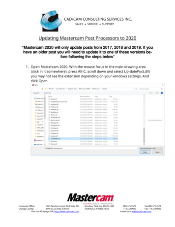
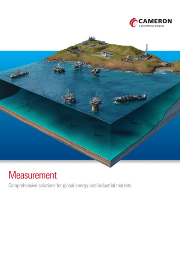
Types of Manufacturing Systems1. Continuous-flow processes. Continuous dedicated production of large amount of bulkproduct. Continuous manufacturing is represented by chemicals, plastics, petroleum, andfood industries.2. Mass production of discrete products. Dedicated production of large quantities of oneproduct (with perhaps limited model variations). Examples include automobiles,appliances and engine blocks.3. Batch production. Production of medium lot sizes of the same product. The lot may beproduced once or repeated periodically. Examples: books, clothing and certain industrialmachinery.4. Job-shop production. Production of low quantities, often one of a kind, of specializedproducts. The products are often customized and technologically complex. Examples:prototypes, aircraft, machine tools and other equipment.IITK ME 761A Dr. J. Ramkumar20
Continuous-flowproductionMass productionProductionquantityBatch productionJob shopproductionProduct varietyIITK ME 761A Dr. J. Ramkumar21
CategoryAutomation achievementsContinuous-flow process Flow process from beginning to end Sensors technology available to measure important processvariables Use of sophisticated control and optimization strategies Fully computer automated linesMass production of discrete products Automated transfer machines Dial indexing machines Partially and fully automated assembly lines Industrial robots for spot welding, part handling, machineloading, spray painting, etc. Automated material handling systems Computer production monitoringBatch production Numerical control (NC), direct numerical control (DNC),computer numerical control (CNC). Adaptive control machining Robots for arc welding, parts handling, etc. CIM systems.Job shop production Numerical control, computer numerical controlIITK ME 761A Dr. J. Ramkumar22
Computer Technology in AutomationMost of the automated production systems implemented today make use ofcomputers. CAD/CAM in addition to its particular emphasis on the use ofcomputer technology, is also distinguished by the fact that it includes not only themanufacturing operations but also the design and planning functions that precedemanufacturing.To emphasize the differences in scope between automation and CAD/CAM,consider the following mathematical model:IITK ME 761A Dr. J. Ramkumar23
TTlc BQT1 BT2 T3TTcl total time during the product life cycleB The number of batches produced throughou t the product life cycle.Q The number of units produced in each batch.T1 The time required to produce one unit of product.T2 The time associated with planning and setting up foreach batch of production .T3 The time required for designing the product and for all the otheractivities that are accomplish ed once for each different product .Tlc The average time spent on each unit of productT3T2during its life cycle T1 QBQIITK ME 761A Dr. J. Ramkumar24
T1The most important term in mass production and batchproductionT2 & T3 become very important in job shopmanufacturing.Automation technology is concerned with reducingT1 &T2the with emphasis on the unit production timeT1CAD/CAM concerned with reducing all three terms, but is perhapsfocused onterms. The emphasis in CAD/CAM includesthe design and planning function of the productlifeTcycle.T2 &3IITK ME 761A Dr. J. Ramkumar25
Advantages of CAD/CAM systems Greater flexibility.Reduced lead times.Reduced inventories.Increased Productivity.Improved customer service.Improved quality.Improved communications withsuppliers. Better product design.Greater manufacturing control.Supported integration.Reduced costs.Increased utilization.Reduction of machine tools.Less floor space.IITK ME 761A Dr. J. Ramkumar26
Introduction to Geometric Transformation Computer graphics plays an important role in the productdevelopment process by generating, presenting, andmanipulating geometric models of objects. During the product development process, for properunderstanding of designs, it is necessary not only to generategeometric models of objects but also to perform suchmanipulations on these objects as rotation, translation andscaling.IITK ME 761A Dr. J. Ramkumar27
Introduction to Geometric transformation Essentially, computer graphics is concerned with generating, presenting andmanipulating models of an object and its different views using computer hardware,software and graphic devices. Usually the numerical data generated by a computer at very high speeds is hard tointerpret unless one represents the data in graphic format and it is even better if thegraphic can be manipulated to be viewed from different sides, enlarged or reducedin size. Geometric transformation is one of the basic techniques that is used to accomplishthese graphic functions involving scale change, translation to another location orrotating it by a certain angle to get a better view of it.IITK ME 761A Dr. J. Ramkumar28
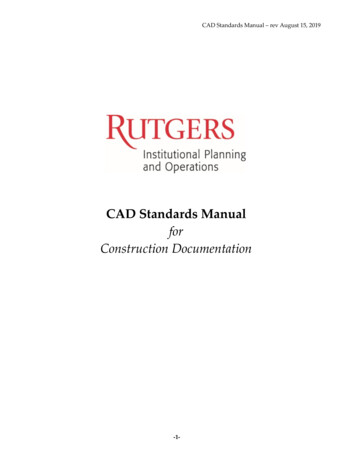
2D TransformationsIITK ME 761A Dr. J. Ramkumar29
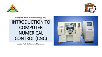
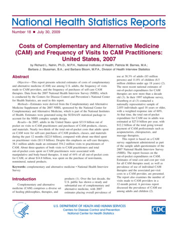
Rotation About the Originy-axisTo rotate a line or polygon, we must rotate each ofits vertices.(x2,y2)(x1,y1)To rotate point (x1,y1) to point (x2,y2) we observe:rBAFrom the illustration we know that:sin (A B) y2/r cos (A B) x2/rsin A y1/rcos A x1/r(0,0)IITK ME 761A Dr. J. Ramkumarx-axis30
Rotation About the OriginFrom the double angle formulas:sin (A B) sinAcosB cosAsinBcos (A B) cosAcosB - sinAsinBSubstituting:y2/r (y1/r)cosB (x1/r)sinBTherefore:y2 y1cosB x1sinBWe havex2 x1cosB - y1sinBy2 x1sinB y1cosBP2 (x2)(y2)RP1(cosB -sinB) (sinB cosB).(x1)(y1)IITK ME 761A Dr. J. Ramkumar31
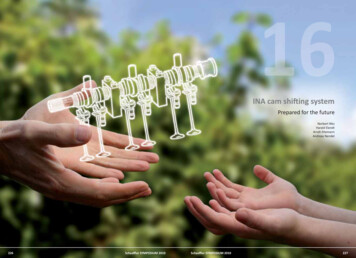
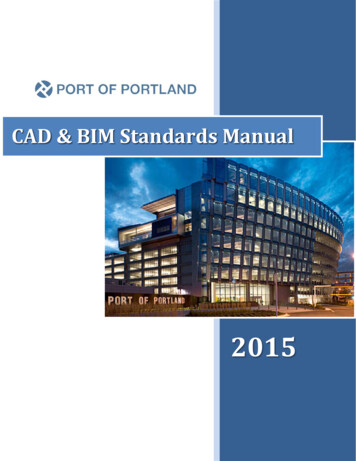
TranslationsMoving an object is called a translation. We translate a point by adding to the x and y coordinates,respectively, the amount the point should be shifted in the x and y directions. We translate anobject by translating each vertex in the object.P2 P 1 TTyTxP1 ( x1 )( y1 )T ( tx )( ty )P2 (x1 tx)(y1 ty)IITK ME 761A Dr. J. Ramkumar32
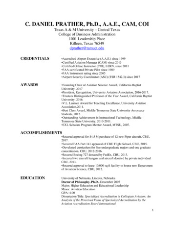
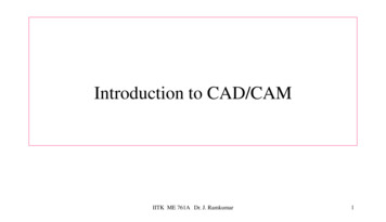
ScalingChanging the size of an object is called a scale. We scale an object by scaling the x and y coordinatesof each vertex in the object.P2 S P1S (sx 0)(0 sy)P1 ( x1 )( y1 )P2 (sxx1)(syy1)IITK ME 761A Dr. J. Ramkumar33
Homogeneous CoordinatesAlthough the formulas we have shown are usually the most efficient way to implement programs todo scales, rotations and translations, it is easier to use matrix transformations to represent andmanipulate them.In order to represent a translation as a matrix operation we use 3 x 3 matrices and pad our points tobecome 1 x 3 matrices.cos øsin ø0-sin øcos ø0001S Sx000Sy0001T 100010TxTy1Rø IITK ME 761A Dr. J. RamkumarPoint P (x)(y)(1)34
Composite Transformations - ScalingGiven our three basic transformations we can create other transformations.Scaling with a fixed pointA problem with the scale transformation is that it also moves the object being scaled.Scale a line between (2, 1) (4,1) to twice its length.(2 00) (4)(2)(0 10)(1)(1)(0 01)(1)(1)(2 00) (4)(8)(0 10)(1)(1)(0 01)(1)(1)01Bef oreAfte r23IITK ME 761A Dr. J. Ramkumar4567891035
Composite Transforms - Scaling (cont.)If we scale a line between (0, 1) (2,1) to twice its length, the left-hand endpoint does not move.(2 0(0 1(0 00)0)1)(2 0(0 1(0 00)0)1) (0)(1)(1) (2)(1)(1)(0)(1)(1)(0)(1)(1)Bef oreAfte r012345678910(0,0) is known as a fixed point for the basic scaling transformation. We can used compositetransformations to create a scale transformation with different fixed points.IITK ME 761A Dr. J. Ramkumar36
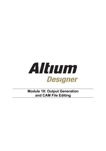
Fixed Point ScalingScale by 2 with fixed point (2,1) Translate the point (2,1) to the origin Scale by 2 Translate origin to point (2,1)(1 0(0 1(0 02)1)1)(2 0 -2)(0 1 0)(0 0 1)(2 0 -2)(0 1 0)(0 0 1)(2 0 0) (1 0 -2)(0 1 0) (0 1 -1)(0 0 1) (0 0 1)(2) (1)(1)(4) (1)(1) (2 0 -2)(0 1 0)(0 0 1)(2)(1)(1)Bef oreAfte r(6)(1)(1)0123IITK ME 761A Dr. J. Ramkumar4567891037
More Fixed Point ScalingScale by 2 with fixed point (3,1) Translate the point (3,1) to the origin Scale by 2 Translate origin to point (3,1)(1 0 3)(0 1 1)(0 0 1)(2 0 0) (1 0 -3)(0 1 0) (0 1 -1)(0 0 1) (0 0 1)(2 0 -3)(0 10)(0 0 1) (2)(1)(1)(1)(1)(1)(2 0(0 1(0 0 (4)(1)(1)(5)(1)(1)-3)0)1) (2 0 -3)(0 1 0)(0 0 1)Bef oreAfte r012IITK ME 761A Dr. J. Ramkumar34567891038
Rotation about a Fixed PointRotation of ø Degrees About Point (x,y) Translate (x,y) to originRotateTranslate origin to (x,y)(x,y)(1 0(0 1(0 0x)y)1)(x,y)(cosø -sinø 0)(1 0 -x)(cosø -sinø -xcosø ysinø x )(sinø cosø 0)(0 1 -y) (sinø cosø -xsinø - ycosø y )(001)(0 0 1)(001)You rotate the box by rotating each vertex.IITK ME 761A Dr. J. Ramkumar39
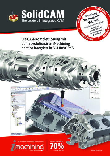
ShearsOriginal Datay Shearx Shear1 0 0a 1 00 0 11 b 00 1 00 0 1GRAPHICS -- x shear -- GRAPHICSIITK ME 761A Dr. J.
CAD/CAM in addition to its particular emphasis on the use of computer technology, is also distinguished by the fact that it includes not only the manufacturing operations but also the design and planning functions that precede manufacturing. To emphasize the differences in scope between automation and CAD/CAM, consider the following mathematical model: Computer Technology in Automation IITK ME .