Transcription
CAD Standards Manual – rev August 15, 2019CAD Standards ManualforConstruction Documentation-1-
CAD Standards Manual – rev August 15, 2019TABLE OF CONTENTSINTRODUCTION31.0.0 CAD STANDARDS CHECKLIST42.0.0 CAD DRAWING PRODUCTION5 - 11CAD StandardsSurvey/GIS StandardsDesign Standards2.1.0FILE FORMAT and SETUP2.1.1Electronic File Format & Submission2.1.2Drawing Organization2.1.3Layout / Plotting Settings2.1.4Scale and Units2.1.5Fonts and Text Styles2.1.6Blocks2.1.7Dimension Settings2.1.8Border / Title Blocks2.1.9Policy on Model Space and Paper Space2.1.10 Policy on External Reference Files (Xrefs)2.2.0LAYERING2.2.1General Rules about Uses2.2.2Attributes (Colors, Pens, and Linetypes)2.3.0POLICY on CAD FILE TRANSLATION2.3.1Error-free AutoCAD Drawing Deliverables2.3.1Translation Testing Recommended3.0.0 ROOM NUMBERING ON FLOOR PLANS4.0.0 DRAWING SUBMISSION PROCESS4.0.11111 - 12GENERAL REQUIREMENTS-2-
CAD Standards Manual – rev August 15, 2019INTRODUCTIONCAD STANDARDSThe purpose of this document is to serve as a specification for producing and delivering CAD drawings for RutgersUniversity–Institutional Planning and Operations (IPO) Construction Projects. The guidelines are intended toensure the successful use and control of CAD systems and data throughout Rutgers University.These requirements must be followed and met by in-house and outside A/E firms. The main A/E firm shall enforcethese standards with their sub-consultant A/E firms. All submitted CAD drawings that do not conform to thefollowing criteria shall be returned. The drawings are to be re-submitted once all requirements have been met.(This CAD Standards Manual supersedes any previous standards pertaining to anything set forth in this document.This CAD Standards Manual may change without notice; use links below to ensure you have the current edition.)Before a project can be closed out and final payment from Rutgers University rendered, all specified materials mustbe submitted to the appropriate Rutgers University Project Manager or representative in accordance with theproduction standards and special instructions described throughout this document.A signed copy of the CAD Standards Checklist found in Section 1.0.0 (page 4) of this document must also besubmitted with the CAD drawings submitted during Project Phases II, III, IV(a), IV(b), & V of the project. Whena CAD Standard Checklist has been signed and submitted, the A/E firm is assuring that all drawings submittedconform to the required standards and guidelines set forth in this document. To ensure/obtain the latest CADStandards & all standard files mentioned in this document please see the links below.To ensure you have the latest CAD Standards please visit the link below to /CAD Standards Manual.pdfTo download the latest CAD Standards & associated files please visit the link VEY/GIS STANDARDSAll survey/civil/site work must follow Rutgers Universities Survey & GIS Standards. All drawings created underthe Surveying & GIS Standards must also adhere to the CAD Standards. Failure to comply with any of the followingstandards shall be denied, returned & must be resubmitted.To review the Surveying Standards please visit the link To review the GIS Standards please visit the link IGN STANDARDSTo review the latest Design Standards please visit the link n-standards-3-
CAD Standards Manual – rev August 15, 20191.0.0 CAD STANDARDS CHECKLISTDrawings submitted for a Rutgers University project must be accompanied by the following checklist. When achecklist has been signed and submitted, the vendor (architect, engineer, contractor, etc.) is assuring that allmaterials adhere to the standards and guidelines set forth in this document.2.0.0 CAD DRAWING PRODUCTION2.1.0FILE FORMAT and SETUP Electronic File Format & Submission Drawing Organization Layout / Plotting Settings Scale and Units Fonts and Text Styles Blocks Dimension Settings Border / Title Blocks Policy on Model Space and Paper Space Policy on External Reference Files (Xrefs)2.2.0LAYERING General Rules about Uses Attributes (Colors, Pens, Linetypes)2.3.0POLICY on CAD FILE TRANSLATION Full AutoCAD Compliance Translation Testing Recommended3.0.0 ROOM NUMBERING ON FLOOR PLANS4.0.0 PROJECT PHASE SUBMISSIONS (Check box that applies to this submission) Phase II – Schematic Design (PDF)Phase III – Design Development (PDF)Phase IV(a) – 50% Contract Docs (PDF)Phase IV(a) – 90% Contract Docs (PDF)Phase IV(a) – 100% Contract Docs (PDF)Phase IV(b) – Signed Bid Set (PDF,DWG, & RVT, if used) Phase IV(b) – Addendum #1 (PDF)Phase IV(b) – Addendum #2 (PDF)Phase IV(b) – Conforming Set (PDF & DWGBase Floor Plans)Phase V – Signed Record Set (PDF)Phase V –Record Set (DWG & RVT, if used)OtherName (please print)Signature:Phone Number:Date:-4-
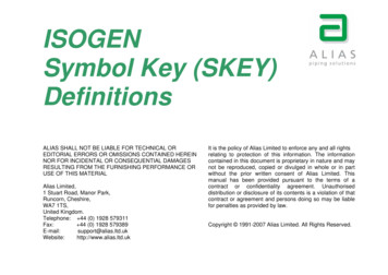
2.0.0CAD DRAWING PRODUCTION2.1.0FILE FORMAT and SETUPCAD Standards Manual – rev August 15, 20192.1.1Electronic File Format & SubmissionA CAD Start Package shall be supplied to all A/E Firms upon award of a project. Contact the Project Manager toreceive this package (or see page 3 for a direct link). Upon completion of the Phase IV(b) “Signed Bid Set,” the A/EFirm shall submit a complete set of drawings in PDF (signed by A/E); DWG (AutoCAD Release 2019); and, if used,RVT (Revit 2019). Upon completion of the Phase IV(b) “Conforming Set,” the A/E Firm shall submit a complete setof drawings in PDF (signed by A/E) and DWG (only base Architectural Floor Plans with correct room numbers anddescriptions). Upon completion of the Phase V “Signed Record Set” and the Phase V “Record Set,” the A/E Firmshall submit a complete set of drawings in PDF (signed by A/E); DWG (AutoCAD Release 2019); and, if used, RVT(Revit 2019). For all other submissions, single-layered and unprotected PDF versions of these drawings shall beprovided. The drawings should be checked to verify that they conform to all the standards set forth in thisdocument. The Bid Drawing Set and the Record Drawing Set shall be in PDF format with an electronic A/Esignature inserted on each sheet (not a digital signature RU-IPO will not accept digital signatures as they cannotbe edited with University Architect signature, which is necessary for bidding purposes). All files shall besubmitted on CD/DVD media in jewel box or USB/flash drive(s) in plastic sleeve (See Section 4.0.0 for additionalinformation). An alternative method is to upload the files to the FTP Server or BIM 360 Docs (See Project Managerto obtain access).Only ONE Rutgers Project per CD/DVD or USB/flash drive.2.1.2a.Drawing OrganizationAll drawings shall be oriented in the same way with a true North arrow indicatedon all plans and site drawings.b. Xrefs shall contain all the disciplines drawing entities that pertain to eachdrawing on their proper layer (etc.). The Sheet drawings shall contain allannotation, text, schedules, notes, markers (detail, elev., section etc.) drawingtitles (in paper space) and dimensions (in model space).c.Drawings are to be organized and filed in the structure shown in Diagram 1.0,easily read and free of stray elements. All drawing elements must be laid out inthe correct drawing order.d. Each base (xrefs) plan created of each floor must have Polylines drawn on a layerlabeled RM. This layer shall consist of a tracing of every room using a singlecontinuous closed polyline to the face of all walls that define that room. Inaddition, two (2) other continuous closed polylines must be drawn on a layerlabeled GROS – one (1) to the inside face of the outermost building line and one(1) to the outside face of the outermost building line.(See drawingsample pline 02X.DWG in the RU CAD STD ZIP.zip for example.)e.All drawings must be purged completely to remove all unused blocks, dimensionstyles, layers, line types, plot styles, text styles, multi-line styles, etc.f.The A/E shall be responsible for preparation of the bid set of drawings; See Section 4.0.0 for the currentprocedure on handling the Set Process for the Bid, Addenda, Conforming & Record Sets.-5-
CAD Standards Manual – rev August 15, 20192.1.3Layout / Plotting Settings Paper size (set accordingly to border size). Plot Area – Extents Plot Offset – Centered Plot Scale – 1’-0” 1’-0”Plot Style Table – (RU Fac-Std.ctb only)2.1.4Scale and UnitsAll CAD drawings shall be drafted at full scale in architectural units, such that 1 drawing unit equals 1 inch.2.1.5Fonts and Text StylesDrafting ComponentsText StyleFont File NameSizeNotes, Dimensions, General Drafting, Room Names, etc.StandardPalatino Linotype3/32”Drawing Titles (Plan, Elevations, Sections, etc )StandardPalatino Linotype3/16”Title Block – Project & Drawing Title Identification Boxes Standard2Palatino Linotype3/16”Title Block – Lower Fields (dsr, bldg# etc.) IdentificationStandard2Palatino Linotype1/4”BoxOnly these fonts are approvedfor use, unless otherwise agreed to by Rutgers Institutional Planning andOperations. The only exceptions are fonts used in the A/E firm’s logos.2.1.6BlocksRutgers is currently not using or enforcing the use of any particular blocks or libraries. However, Rutgers requiresthat the following general rules be employed when handling block entities:a. All entities within a block must be created on layer 0.b. Drawing entities translated into AutoCAD blocks from non-AutoCAD systems must revert to layer 0 whenexploded within AutoCAD.-6-
CAD Standards Manual – rev August 15, 20192.1.7Dimension SettingsLinesDimension LinesColor BYLAYERLinetype BYLAYERLineweight BYLAYERExtend 1/8”Baseline Spacing 3/8”Suppress 1 & 2 OFFExtension LinesColor BYLAYERLinetype Ext #1&2 BYLAYERLineweight BYLAYERSuppress OFFExtend beyond dim lines 1/8”Offset from origin 1/16”Fixed length extension lines OFFSymbols and ArrowsArrowheadsFirst & Second Architectural TickLeader Right AngleArrow Size 1/8”Arc length symbolPreceding dimension text OnRadius dimension jogJog angle 45Center marksMark OnSize 3/32”TextText appearanceText style StandardText color BYLAYERFill color NoneText height 3/32”Fraction height scale 1.00Draw frame around text NoneFitText placementVertical AboveHorizontal CenteredOffset from dim line 1/16”Text alignmentAligned with dim line OnFit options Either text or arrows (best fit)Text placement Over dimension line, without leaderFine tuning Draw dim line between ext linesPrimary UnitsLinear dimensionsUnit format ArchitecturalPrecision 1/16”Fraction format HorizontalDecimal separatorRound off OffZero suppression0 Feet OnAngular DimensionsUnits format Decimal DegreesPrecision 0Measurement scaleScale factor 0Zero suppressionLeading OffTrailing Off-7-
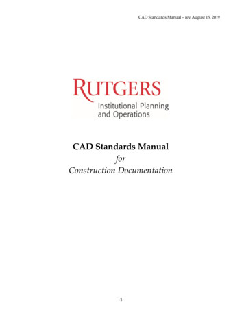
CAD Standards Manual – rev August 15, 20192.1.8Border / Title BlockRutgers University issues a standard border / title block that shall be used in all “Rutgers University Drawings”and which is to be xref’d into the sheet files. The border & associated text shall not be altered; if altered in anyway the submission shall be rejected.The border / title block contains attributes that must be filled out properly. These attributes are a separate blockfrom the border, also included in the start package. Additionally, the full titles (logos) of the Project Architect andEngineer must be placed in the proper area. Along with the A/E Logo the title block must contain the Name,License Number and Date of the licensed individual responsible for the corresponding discipline. (Please seebelow for additional information.)All Drawing Revisions must be properly noted in the revision list as depicting the number and date of revisions.They must be noted clearly and concisely and shall include at least 6 lines for revisions. Revisions on the drawingareas shall be clouded and tagged with a delta triangle stating which revision number it in relation to. The revisionnumber in the triangle must coincide with its revision in the revision list.**This diagram is for reference only and not to scale, contents within the border or text may change without notice**-8-
CAD Standards Manual – rev August 15, 20192.1.8.1 SizeIn an effort to maintain consistency in our permanent records of all University buildings, all construction documentsmust be formatted to print in the following standard paper sizes: Arch D - 24" x 36" Arch F - 30" x 42" (preferred size)2.1.8.2 Drawing TitleThe A/E title block and name of project shall be in a vertical format down the right-hand side of the drawing andshall contain the following: The Project Name shall match the title of the project on the project budget analysis sheet (PBA);The Project Number shall be cross-referenced to the budget number;The Building Number (to be provided by the Project Manager); andAn area large enough for A/E's signature and seal.2.1.8.3 Drawing NumberIf the A/E does not have a standard drawing numbering system, the United States National CAD Standard LatestVersion on sheet identification shall be used.2.1.8.4 Title Sheet / Cover SheetA title sheet included in the CAD Start Package shall be included on all projects. Include an index of sheet numbersand drawing titles. This must also be provided in Microsoft Excel format to include drawing title, A/E sheetnumbers, and drawing date. The title sheet shall have the following minimum information (the layout can bealtered to best suit the needs of the project): Project name, campus, and address;Name, address, phone number, email address of the A/E and any consultants used on the project;Index of all drawings included in the Contract Documents;Location map indicating the location of the project on the particular campus or within the town where it islocated. (Campus maps are available from the Project Manager);Key Pl
CAD Standards Manual –rev August 15, 2019-4-1.0.0 CAD STANDARDS CHECKLIST Drawings submitted for a Rutgers University project must be accompanied by the following checklist. When a checklist has been signed and submitted, the vendor (architect,