Transcription
1616Cam shifting systemCam shifting systemCam shifting system16INA cam shifting systemPrepared for the futureNorbert NitzHarald ElendtArndt IhlemannAndreas Nendel226Schaeffler SYMPOSIUM 2010Schaeffler SYMPOSIUM 201016227
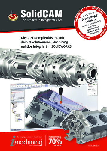
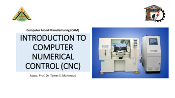
Cam shifting systemA major objective in the further development ofinternal combustion engines is the reduction offuel consumption and CO2 emissions. Future exhaust regulations will also require a further reduction of emissions.The internal combustion engine will remain an important drive source for motor vehicles, even ifthere are currently a lot of activities in the direction of electric drives and fuel cells. The efficiencyof the internal combustion engine must be continuously increased.Important potential areas during the optimizationof the engine are the reduction of the charge cyclework, the optimization of the charge motion, influencing the percentage of residual exhaust gases,especially under partial load, the control of thetemperature at the start of the compression strokeand metering the mass of the fresh air. Variabilityin the valve train is required in order to implementthese measures.The implementation options available rangefrom pure cam phase adjustment and partiallyvariable valve lift to fully-variable valve lift. Thegreater the degree of variability that is used,the greater the potential that can be achieved.Figure 1228Partially-variable valve train componentswith electro-hydraulic actuationINA has been developing, amongst other things,partially-variable valve trains for over 20 yearsand looks back on over 10 years of volume production of the switchable tappet. INA was alsoinvolved in the development of the cam shiftingsystem and has further developed the Audi ValveLift System which is currently on the market. Theaim of this publication is to show how it hasbeen possible to achieve more functionalitywhile maintaining the same design space conditions by means of an intelligent actuator concept.State of the artThere are many different, partially-variable valvetrain concepts with different actuator systems andimplementation levels of variability for finger-follower valve trains.Figure 1 shows well-known electro-hydraulic systems. The switchable pivot element (picture on theleft) enables valve/cylinder deactivation. The switchable roller finger follower (picture on the right) canbe used to perform cam profile switching or valve/cylinder deactivation.In addition, there is also the possibility of varying the lift directly on the camshaft using electro-mechanical actuators, as in the Audi ValveLift System (AVS) (Figure 2) [1]. This two-stageswitching system comprises a base shaft, onecam element per cylinder, the associated fingerfollowers and pivot elements as well as two actuators per cam element. The cam element isfixed for co-rotation with the base shaft bymeans of axial splines but can be moved in anaxial direction. The cam element is supported bythe camshaft bearing located centrally betweenthe valves. The cam element for both valves includes two sets of associated cams and the control grooves. In the current arrangement, thecam element is shifted on the base shaft in bothaxial directions using two S-shaped groove contours and two electrically controlled actuators(Figure 2).Schaeffler SYMPOSIUM 201016Norestrictionsof valve liftcurvesFor example, the combination of a variablecamshaft phasing unit and a partially-variablevalve train has proven advantageous. This paper concentrates mainly on partially-variablevalve trains.Figure 2Audi Valve Lift System [1]Comparisonbetween the camshifting system andother familiarswitching systemsA comparison of these different systems showsthat electrically actuated cam shifting systemshave a number of advantages.Increased operationaltemperature rangeElectro-hydraulically actuated systems have limitations in the low temperature range (Figure 3).Only one switching is permissible with oil pressure at oil temperatures below 20 C. Switchingis not permitted in the opposite direction lessthan 20 C due to the high oil viscosity at lowtemperatures and the associated rapid increasein faulty switching. Unlimited operation is usually only ensured for an oil temperature of 20 Cand above. The cam shifting system operateswithout switching faults in a significantly largeroperating range due to the electric actuator andthe positively controlled switching (Figure 3).There is also further potential for extending theoperating range.Another disadvantageof well-known components with lost motionelements (switchabletappets,switchableroller finger followers)is the restricted freedom for the design ofthe valve lift curves.For example, theswitchable roller fingerfollower comprises a primary lever and a secondary lever. The lift on the primary lever is alwaysapplied, while the lift on the secondary lever canbe blanked out by switching. The smaller lift mustalways be overlapped by the larger lift or thesmaller lift must be completely outside the rangeof the large lift (Figure 4). The individual lifts cannot be realized if both curves intersect. A contactElectro hydraulic actuated systemsOil temperature in CIntroductionCam shifting system150200One switching allowedfrom low to highpressure mode5003500Engine speed in 1/minINA cam shi ing system1500-10-30Opera on rangeRestricted opera on0Figure 3Schaeffler SYMPOSIUM 201016Opera on rangeRestricted opera on-30Oil temperature in C163500Engine speed in 1/minComparison of operating ranges229
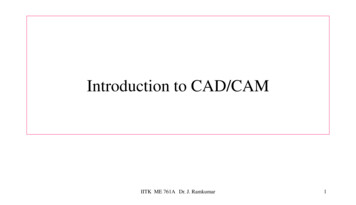
16Cam shifting systemchange from one cam to another would occurduring the valve lift and the overlapped lift curvewould be realized. The cam shifting system doesnot have this restriction. The lift curves can be selected freely.No hydraulic systemrequired for switchingThe oil circuit and especially the oil pump must beappropriately dimensioned in electro-hydraulicallyactuated systems in order to ensure the requiredminimum oil pressure is maintained at all switchingpoints. However, it is usually not possible to shiftthe camshaft phasing system and switching components simultaneously. The cam shifting systemwith electric actuation can be used at any time andis independent of the oil circuit.Positively-controlledswitching within one rotation of the camshaftThe cam shifting system is based on positive control during the switching operation, i.e. the camelement must be shifted after one rotation of thecamshaft. It is possible that the switching operation may take longer than one rotation on hydrauli-Valve li in mmElectro hydraulic actuated systems12108642025 5075 100 125 150 175 200 225Angle camsha in Valve li in mmINA cam shi ing system1210864200Figure 42550 75 100 125 150 175 200 225Angle camsha in Restrictions for the design of the valve lift16cally actuated systems, especially at low temperatures. Cyclical switching is, therefore, not possibleat low temperatures. The cam shifting system enables cyclical switching within one rotation of thecamshaft. Faulty switching, which occasionally occurs with hydraulically actuated systems, are prevented with the cam shifting system.Switching of individualcylinders is possibleSwitching of individual cylinders on electro-hydraulically actuated systems is only possible with additional outlay. In this case, more switching valvesmust be installed and the design of the hydraulic oilcircuit is more complex. The cam shifting systemwith its clear assignment of actuators per cylinderenables switching of individual cylinders without additional complexity. This allows further potential forfuel consumption savings during adaption of the engine control unit without incurring additional costs.No additional valve liftvariationLocking mechanisms, which are based on pistons,show backlash in the lock due to tolerances. Thisbacklash, which varies depending on the design,leads to a corresponding variation of the valve liftduring the secondary lift. The cam shifting systemhas in comparison to switchable roller finger followers no additional valve lift variation.Low moving mass/mass moment of inertia0230Cam shifting systemThe switchable roller finger follower has a largermoving mass and a larger moment of inertia thanthe cam shifting system due to its design with twolevers arranged in parallel. The basic roller fingerfollower design for the cam shifting system is onlyslightly modified compared with well-known standard finger followers. This allows the original valvesprings to be maintained and higher friction in thevalve train is prevented. The valve lift curves in thecam shifting system can be freely selected withinthe limits of accelerations which are possible in finger follower valve trains. Restrictions with switchable roller finger followers often occur due to thegreater mass moment of inertia. The valve liftcurve of switchable roller finger followers oftenhas to be adapted in order to restrict the loads.Schaeffler SYMPOSIUM 2010Figure 5Comparison of the thermodynamic potential of different conceptsSystem flexibility for CPS,CDA and CAI/HCCIFlexible systems with a greater degree of freedomare often required during development in order totest different concepts. Engine manufacturers continuously strive to use systems for volume production, which are flexible enough for several engineconcepts. This eliminates significant costs and enables a reduction in the variety of components.For example, there are different requirementswhen starting the engine (start with a small orlarge valve lift). These are realized on hydraulicallyactuated systems by using different locking mechanisms (unlocked or locked in a depressurized state)depending on the application.This functionality is achieved on the cam shiftingsystem simply by varying control of the actuators.The cam shifting system can be simply adapted fordifferent requirements while maintaining the important functions without any technical disadvantages.MotivationIn total, the described advantages of the cam shifting system result in the achievement of greatersavings in fuel consumption compared with switchable roller finger followers.Schaeffler SYMPOSIUM 2010The proposed three-stage valve lift variation incombination with an electric actuator comescloser to the performance of a fully-variablevalve train, but has a more favorable cost-benefit ratio (Figure 5). This was the reason why INAfurther developed the three-stage cam shiftingsystem.16INA cam shiftingsystemDesign and functionThe objective for the INA cam shifting system is toimplement a three-stage switching system withoutmaking significant changes to the basic idea, i.e.“shifting the cam element axially on a base shaft ”.An additional INA requirement is that the camshifting system should be adaptable for the largestpossible range of engine architecture with different valve and cylinder spacing.The core of the cam shifting system is the groovecontour, in which the actuator pin meshes andthe cam element for a cylinder is shifted axially onthe base shaft. The design space available for theshift grooves for implementing the three switch-231
16Cam shifting system64200Figure 64590135 180 225 270 315 360Angle camsha in Axial lift of the cam element with thedouble S-grooveing stages is significantly restricted with the existing valve and cylinder spacing. A design with twoS-grooves (Figure 2) is, therefore, not possible. Adouble S-groove proved to be the most promisingfollowing an analysis of different groove configurations. This groove design generates motion inboth shift directions in a base circle phase of approximately 210 degrees of camshaft rotation. Inaddition to both axial motions, an entry zonemust also be set aside in the groove base for theactuator pin motion in this phase (approximately70 degrees of camshaft rotation). This meansthere is effectively only approximately 70 degreesof camshaft rotation available for shifting the camelement axially. The double S-groove (Figure 6)was optimized with a simulation model. The contact forces on the actuator pin were kept at almost the same level as those on the S-grooveused in volume production (Figure 2), althoughsignificantly less phase angle is available. Figure 6shows an example of the axial lift of the cam element with the double S-groove.Figure 8 shows that the double S-groove must bepositioned between the cams when an additionalbase shaft bearing support is located between thecylinders. This defines the camshaft design of theINA three-stage cam shifting system.Figure 10 Three-stage detentFigure 8INA three-stage cam shifting systemThe INA cam shifting system can also be a twostage design (Figure 9). In this case, only a one-pinactuator is required per cylinder and the base shaftbearing support can be located between thevalves.The cam element bearing support has to be redefined for the three-stage cam shifting system.Cam sha bearings in-between the valvesFigure 9INA two-stage cam shifting systemCam sha bearings in-between the cylindersFigure 723216Where the bearing support is arranged betweenthe valves (Figure 7), the bearing web has insufficient width if there is narrow spacing between thevalves. Therefore, an arrangement with the baseshaft bearing support between the cylinders is themost promising approach here (Figure 7).8Axial li in mmCam shifting systemDifferent camshaft bearing supportsThe cam element is fixed for simultaneous rotationwith the base shaft by means of axial splines allowing it to move in an axial direction. Cam profileswitching means that the cam element is shiftedaxially by one cam width on the base shaft. If thecam element is not actuated, the detent (Fig-Schaeffler SYMPOSIUM 2010ure 10) fixes the cam element in the correspondingposition on the base shaft. The detent has onespring-loaded ball per cylinder.The three recesses for locking the cam element detent are assigned to the three cams (Figure 10).An INA two-pin actuator acts on the doubleS-groove in order to switch between the three camlifts. If the actuator is activated using a control signal from the engine control system, on
Comparison between the cam shift ing system and other familiar switching systems A comparison of these different systems shows that electrically actuated cam shifting systems have a number of advantages. Increased operati onal temperature range Electro-hydraulically actuated systems have limi-tations in the low temperature range (Figure 3). Only one switching is permissible with oil pres-sure .