Transcription
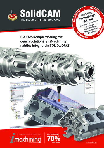
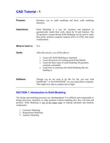
University of TechnologyIndustrial EngineeringCAD/CAMThird ClassCAD/CAM1. CAD/CAM Technology:The story of CAD/CAM was accelerated in early 1950s. Up to year2012ithas become one of the supreme technology available on Planet earth.It is being used in almost all the fields of engineering but primarily inmechanical engineering branches. The development in the field is stillgaining speed. CAD Technology Design Techniques Computers. The CAD Process is the subset of the Design process. The CAM Process is a subset of Manufacturing Process. Integration of CAD and CAM leads to automation. ( as show below)Dr. Amjad Barzan Abdulghafour
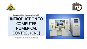
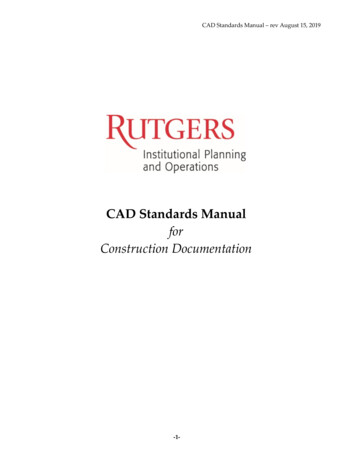
University of Technology Industrial EngineeringCAD/CAMThird Class2. Computer Aided Design (CAD):In general, a Computer Aided Design (CAD) package has threecomponents: a) Design, b) Analysis, and c) Visualization, as shown in thesketch. A brief description of these components follows.a) Design: Design refers to geometric modeling, i.e. 2-D and 3-D modeling,including, drafting, part creation, creation of drawings with various views of thepart, assemblies of the parts, etc.b) Analysis: Analysis refers to finite element analysis, optimization, and othernumber crunching engineering analyses. In general, a geometric model is firstcreated and then the model is analyzed for loads, stresses, moment of inertia,and volume, etc.c) Visualization: Visualization refers to computer graphics, which includes:rendering a model, creation of pie charts, contour plots, shading a model,sizing, animation, etc.Each of these three areas has been extensively developed in the last 30 years.Several books are written on each of these subjects and courses are availablethrough the academic institutions and the industry.Dr. Amjad Barzan Abdulghafour
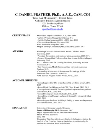
University of Technology Industrial EngineeringCAD/CAMThird ClassMost commercial CAD packages (software) consist of only a singlecomponent: design or analysis or visualization. However, a few of the vendorshave developed an integrated package that includes not only these three areas, butalso includes the manufacturing software (CAM). Due to the large storagerequirement, integrated packages use either an UNIX workstation or a mainframeplatform, and not the popular PC platform. With the improvement in PCcomputing speed, it’s only a matter of time before we see an integrated packagerun on a PC. CAD has revolutionized the modern engineering practice; small andlarge companies use it alike, spending several billion dollars for the initial purchaseor lease alone. CAD related jobs are high in demand and the new graduates haveadvantage over their senior colleagues, as they are more up to date and moreproductive.3. Computer Aided Manufacturing (CAM):CAM is the next stage of CAD. A part created in CAD can bedownloaded and manufactured, without a human hand touching the part.The process is called CAM, and involves CAD, Networking, and NCprogramming, as shown below.Dr. Amjad Barzan Abdulghafour
University of Technology Industrial EngineeringCAD/CAMThird Class4. CAD/CAM History:The concept of CAD and CAM is relatively new. The usage is linkedwith the development of computers. The actual application of CAD/CAM inindustry, academia and government is only approximately 30 years old.Formal courses in CAD and Finite Element Analysis (FEA) were introducedin 1970’s. The major application thrust of CAD came in 1980’s, with theavailability of PCs and workstations. In its early stage of usage, very fewengineering companies could afford the expense of mainframe computers;however, PCs and workstations have evolved into affordable and adequateplatform to support comprehensive CAD packages that initially weredesigned to run on the mainframe platform. A brief history of the evolutionof CAD/CAM, according to the decade and the major CAD/CAMdevelopments, is outlined below.1960’s Development in Interactive computer graphics research Sketchpad system developed by Ivan Sutherland in 1962 CAD term coined First major commercial CAD/CAM software available: CADAM by Lockheed, in1965 Bell Telephone’s - Graphics 1 remote display system developed1970’s Application of CAM in government, industry and academia National organization formed Beginning of usage of computer graphics Turnkey system available for drafting Wireframe and surface modeling software became available Mass property calculation and FEA software became available NC tape generating, verification, and integrated circuit software became availableDr. Amjad Barzan Abdulghafour
University of Technology Industrial Engineering1980’s CAD/CAM used for engineering research and development New CAD/CAM theories and algorithms developed Integration of CAD/CAM Solid modeling software became available Use of PCs and workstation began1990’s Concept of concurrent engineering developed Increased use of CAD/CAM on PCs and workstations Improvements in hardware and softwareDr. Amjad Barzan AbdulghafourCAD/CAMThird Class
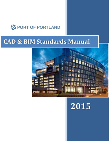
University of TechnologyIndustrial EngineeringCAD/CAMThird ClassCAD/CAM5. Design Process:The process of Design is segmented into Six Stages, details of whichhave been shown in below figure .The design process is repetitive as well ascreative. The repetitive tasks can be performed by computers; however, thecreative tasks (stages 1 and 2) are always done only on the human being.Show in this figure.Stage1: Recognizing the fact that there is a need for a new product forintended function. It may also include the modification in the existingproduct.Dr. Amjad Barzan Abdulghafour
University of Technology Industrial EngineeringCAD/CAMThird ClassStage2: Problem is fully defined in terms of functionality and meeting otherrequirements such as ergonomic, performance-data, statutory, etc.Stage3: The design undergoes synthesis, joining its various elements.Stage4: Product analysis reveals the weaknesses and thus weaknesses canbe considered for improvement. This process is repeated until an acceptableDesign achieved.Stage5: The optimized Design is reviewed from the point of view ofexpected performance. It can be done through proto-type modeling andtesting against the set standard.Stage6: Stages 4 and 5 are repeated until acceptable, optimized design isachieved. These stages are basically iterative in-nature. Iteration depends onthe creativeness, ingenuity (skill for devising) and experience of designersand the software (tools) available. The process (stage 1 and 2) are humandependent while the stages 3, 4, 5 and 6 (four stages) are computer based(CAD).(A) Geometric modeling: - It implies the existence of a computer graphicsscreen and some interaction with the computer to generate the geometry andtopology of the part.(B) Engineering analysis: - Communicates with the data base to retrievethe part description and with the user to obtain the design constraints,boundary conditions, and other details of the analysis.(C) Evaluation module: - Allows the user to check the correctness,manufacturability, and processing details of the part.(D) The drafting and documentation module: - Contains some of both theoldest and newest technologies/Computer plotting of engineering drawings.6. CAD Hardware:There are basically two types of devices that constitute CAD hardware: a)Input devices, and b) Output devices. A brief description follows.Dr. Amjad Barzan Abdulghafour
University of Technology Industrial EngineeringCAD/CAMThird Class6.1. CAD Platform:In general, we can run CAD software on three different CADplatforms: Mainframe, Workstation, and PC. When the CAD programs firstbecame available, they could only be run on a mainframe computer. However, asthe PCs have become faster and cheaper, almost all the CAD vendors haveintroduced a version of their CAD software that will effectively run on a Pentiumor higher computer. Currently, the most popular platforms are PCs andWorkstations. Popularity of Workstations stems from their ability to network easilywith other computers, and also, due to their large memory storage capability.However, PC platform is still the most preferred medium for most engineers.Increasing popularity of the PC platform can be attributed to several factors,including, total user control, the speed, capability of storing large memory, ease ofhardware upgrading and maintenance, and the overall reasonable cost.6.2. Input Devices:These are the devices that we use for communicating with computer,and providing our input in the form of text and graphics. The text input ismainly provided through keyboard. For graphic input, there are severaldevices available and used according to the work environment. A briefdescription of these devices is given here.Dr. Amjad Barzan Abdulghafour
University of Technology Industrial EngineeringCAD/CAMThird ClassMouse: This is a potentiometric device, which contains several variableresistors that send signals to the computer. The functions of a mouse includelocating a point on the screen, sketching, dragging an object, enteringvalues, accepting a software command, etc. Joystick and trackballs areanalogous to a mouse device, and operate on the same principle.Digitizers: Digitizers are used to trace a sketch or other 2-D entities bymoving a cursor over a flat surface (which contains the sketch). The positionof the cursor provides a feedback to the computer connected with the device.There are electrical wires embedded in orthogonal directions that receiveand pass signals between the device and the computer. The device isbasically a free moving puck or pen shaped stylus, connected to a tablet.Light Pens: Lockheed’s CADAM software utilized this device to carry outthe graphic input. A light pen looks like a pen and contains a photocell,which emits an electronic signal. When the pen is pointed at the monitorscreen, it senses light, which is converted to a signal. The signal is sent tothe computer, for determination of the exact location of the pen on themonitor screen.Touch Sensitive Screens: This device is embedded in the monitor screens,usually, in the form of an overlay. The screen senses the physical contact ofthe user. The new generation of the Laptop computers is a good example ofthis device.Other Graphic Input Devices: In addition to the devices described above,some CAD software will accept input via Image Scanners, which can copy adrawing or schematic with a camera and light beam assembly and convert itinto a pictorial database.The devices just described are, in general, independent of the CADpackage being used. All commercial CAD software packages contain thedevice drivers for the most commonly used input devices. The devicedrivers facilitate a smooth interaction between our input, the software, andDr. Amjad Barzan Abdulghafour
University of Technology CAD/CAMIndustrial EngineeringThird Classthe computer. An input device is evaluated on the basis of the followingfactors: Resolution Repeatability Accuracy Linearity6.3. Output Devices:After creating a CAD model, we often need a hard copy, using an output device.Plotters and printers are used for this purpose. A plotter is often used to producelarge size drawings and assemblies, whereas, a laser jet printer is adequate toprovide a 3-D view of a model. Most CAD software requires a plotter forproducing a shaded or a rendered view.7. CAD Software:CAD software is written in FORTRAN and C languages. FORTRANprovides the number crunching, whereas, C language provides the visualimages. Early CAD packages were turnkey systems, i.e., the CAD packageswere sold as an integrated software and hardware package, with noflexibility for using second vendor hardware (1970s and 80s). These systemswere based on 16-bit word, and were incapable of networking. The modernCAD software utilizes the open architecture system, i.e., software vendorsdo not design and manufacture their own hardware. Third party software canbe used to augment the basic CAD package. Most popular CAD packagewill facilitate integration of the Finite Element Analysis and other CADsoftware from more than one vendor. For example, IDEAS preprocessor canwork with almost all the FEA packages for pre and post analyses.Networking is an important consideration in applications of CAD software.A model created by one engineer must be readily accessible to others in anorganization, which is linked by a LAN or other means. The designer, analyst,management, marketing, vendor, and others generally share a model. This is theconcurrent engineering in action, mentioned earlier.Dr. Amjad Barzan Abdulghafour
University of Technology Industrial EngineeringCAD/CAMThird Class8. CAD Evaluation Criteria:In the current CAD market, ProE and AutoCAD are arguably themost dominating CAD software. AutoCAD is basically a 2-D program, withsome capability to create 3-D models, whereas, ProE is a truly 3-D CADpackage. Besides this software, there is several other CAD software, listedin the previous section that has sales exceeding 100 millions. No one CADpackage is suitable for all the CAD users in the world. The product we aredesigning dictates the type of CAD package we need. A good CAD packageincludes good software, as well as, a compatible hardware. Following is abrief description of the general criteria for evaluating a CAD package.Hardware: Most desirable features in a good hardware are: Open architecture High speed, large storage Compact size Inexpensive components Inexpensive upgradingSoftware: In general, the most comprehensive software are written tosatisfy almost all the modeling needs of a modeler, consequently, thesoftware tend to be very complex and hard to learn. To create a simplemodel, we go through several unnecessary steps, and lack the intuitivenessof a simple, straightforward program. ProE is a good example, where wehave to go through several layers of menus to create a simple solid. On theother hand, if we were to use a simpler CAD program, the same solid can becreated by only a few simple commands. Th
CAD/CAM Technology: The story of CAD/CAM was accelerated in early 1950s. Up to year 2012ithas become one of the supreme technology available on Planet earth. It is being used in almost all the fields of engineering but primarily in mechanical engineering branches. The development in the field is still gaining speed. CAD Technology Design Techniques Computers. The CAD Process is the subset .