Transcription
CAD Tutorial - 1Purpose:Introduce you to solid modeling and basic solid modelingfunctions.Importance:Solid Modeling is a way for scientists and engineers togeometrically model their work, check for fit and function. The3D geometry created during Solid Modeling can be used to makeblue prints, perform computer analysis (FEA or CFD), and createvisualizations.What to hand in:N/AGoals:After this activity, you will be able to: Software:Learn why Solid Modeling is importantLearn the process for creating good Solid ModelsLearn the basic types of solid modeling 3D geometrycreations commandsLearn how to customize the Solid Modeling files forhanding inThough you do not need to do this for lab, you may loadSolidWorks or Pro/ENGINEER on your home/dorm computer.This might save trips to campus late at night.SECTION 1: Introduction to Solid ModelingThe design and modeling processes are interdependent! It is difficult and irresponsible todesign processes, machines, or other products without modeling how they will look andperform. Solid Modeling is one of the major steps in making machines and machinecomponents.1. Customer Modeling2. Requirement Modeling3. Analytic Modeling
4. Solid Modeling (Geometric Modeling)5. Functional ModelingParametric Solid Modeling (PSM) is a useful tool, which will help you geometricallymodel your design(s). Solid modeling is not an easy skill to learn. You must know: How to run the software:How to use the software to get the results that you want (design intent)Eventually, as you learn how to build models with the correct design intent, you will findthat solid modeling will: Allow you to change yourdesign with little effortHelp illustrate your designsto othersMake sure parts fit togetherCheck for proper functionCheck for interferenceMake drawings / blue printsThe introduction of PSM does not mean the demise of sketching!!! Sketching is oneof the most valuable skills a designer can have to quickly convey ideas and layout adesign. As a matter of fact, it is often a GOOD idea to sketch out your designs beforeyou proceed with PSM so that you can start to recognize the major shapes that make upyour part. This is important as robust solid models are made of the fewest and least likelyto change features one need. You will come to learn that the process of rough sketching isvery similar to the process of solid modeling.SECTION 2: PSM ProcessLike the design process, PSM is best done when following a process. The general stepsare listed below, you will learn them as you go through the tutorials.1. Determine what you want to do/make2. Develop concepts for getting the job done (i.e. what are the bestshapes to model this?)3. Determine your design intent4. Draw/input any supporting geometry or sketches needed5. Draw a 2-D sketch6. Extrude, Revolve, Sweep, or Loft the 2-D sketch to make a 3-Dobject7. Combine these objects into assemblies8. Make drawing of individual parts and assemblies with dimensions& tolerances
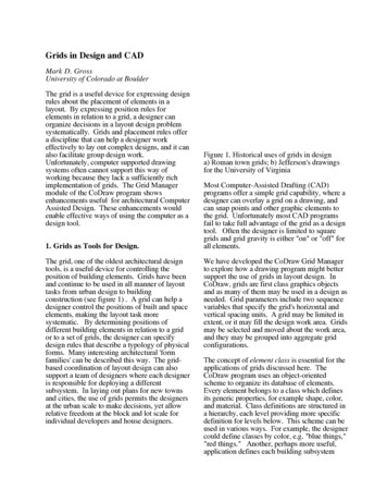
9. Make files for use with: Computer aided manufacturing (CAM) softwareFEA (finite element analysis) softwareDynamic modeling softwarePhotographic rendering softwareOthersSECTION 3: Basic Functions in Parametric Solid ModelingBefore discussing PSM in more detail, the reader should be familiar with the basicoperations which can be used to make a solid model of a part/product. Note that whenapplicable, the illustrations below start out with a 2D sketch, then they are transformedinto 3-D geometry. The basic process may differ somewhat, depending on the CADprogram you use.FunctionWhat it's good forProcessTo view, go to the Animations sectionSolid Extrusions areoften used to: Make the basepart of a modelAddingbosses/features toa modelSolid ExtrusionSubtracting portion of amodel to form a featurelike: Cut/Slot ExtrusionHolesKeywaysCavities1. Pick/make asketch plane2. Draw &dimension a 2-Dsketch3. Issue "extrudeboss" command4. Define extrusiontype (blind,midplane, etc.)5. Enter extrusiondepth ifnecessary1. Pick/make asketch plane2. Draw &dimension a 2Dsketch3. Issue "extrudecut/slot"command4. Define extrusiontype5. Enter extrusiondepth ifnecessary
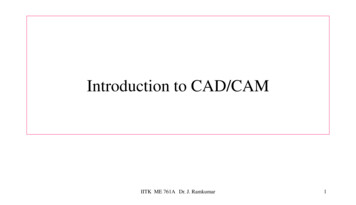
Adding features to amodel which can best bedescribed in R-θcoordinates. Thesefeatures include: Revolved Extrusion Base of a modelExternalpipes/ductsTorous shapedfeaturesAnnularfeatures/ribsSubtracting a portion of amodel which can best bedescribed in R-θcoordinates. Thesefeatures include: Revolved CutLoft [blend in Pro-E] Internalpipes/ductsExternal irregularshaped groovesAdding/subtractingfeatures to a modelwhere two ends of thefeature are described bydifferent x-sections(sketches) and the xsections must transforminto each other. Base of a modelExternal features1. Pick/make asketch plane2. Draw &dimension a 2Dsketch3. Draw acenterline aroundwhich to revolve4. Issue "revolvecut/slot"command5. Enter revolutiondirection & depth(θ) if necessary1. Pick/make asketch plane2. Draw &dimension a 2Dsketch3. Draw acenterline aroundwhich to revolve4. Issue "revolvecut/slot"command5. Enter revolutiondirection & depth(θ) if necessary1. Pick/make asketch plane2. Draw &dimension 1stsketch3. Draw &dimension 2ndsketch4. Issue "loftcommand"
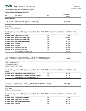
Adding or subtractingparts to/from a modelwhich can best bedescribed by "sweeping"a x-section along a predescribed path: Sweep Base of a modelExternalpipes/ductsSpringsTorous shapedfeaturesAnnular featuresMaking thin parts suchas: ShellCupsBowlsThin casings1. Pick/make asketch plane2. Draw &dimension sweeppath3. Draw &dimension sweepx-section4. Issue "sweep"command1. Issue "shell"command2. Pick a cutplane/face/surface3. Pick shelldirection/properties4. Pick shellthicknessSolidWorks is a registered trademark of SolidWorks Corporation. Pro/ENGINEER is a registeredtrademarks of Parametric Technology Corporation or its subsidiaries in the U.S. and in other countries.
SolidWorks or Pro/ENGINEE Ron your home/dorm computer. This might save trips to campus late at night. SECTION 1: Introduction to Solid Modeling The design and modeling processes are interdependent! It is difficult and irresponsible to design processes, machines, or other products without modeling how they will look and perform. Solid Modeling is one of the major steps in making machines .