Transcription
Module 19: Output Generationand CAM File Editing
Module 19: Output Generation and CAM File Editing19.1 Bill of Materials . .8Generating a Bill of Materials .19-1Using databases with the Bill of Materials.19-2Setting up the link to a database.19-2Linking the database to the Bill of Material .19-4Adding PCB Information Directly to a BOM .19-4Supplier Options.19-5Exporting the Report .19-6Using Excel Templates.19-619.2 Output Generation. 19-819.2.1 Creating a new Output Job file.19-819.2.2 Setting up Print job options .19-919.2.3 Creating CAM files .19-1019.2.4 Gerber .19-1119.2.5 NC Drill .19-1119.2.6 ODB Output.19-1219.2.7 Pick and Place.19-1219.2.8 Testpoint report .19-1219.2.9 Smart PDFs.19-1219.2.10 Publish To Web .19-1319.2.11 Running the Output Generator.19-1819.2.12 Exercise – adding an OutJob file to the project .19-1819.3 CAM Editor . 3.8Setting up data to use in the CAM Editor .19-20Import Data.19-20Layer Type Assignments.19-21Board Stackup and Drill Sets .19-23Netlist Extract .19-24Running a DRC .19-25Using Auto Fix .19-28Checking Remaining Violations .19-29Software, documentation and related materials:Copyright 2009 Altium Limited.All rights reserved. You are permitted to print this document provided that (1) the use of such is for personal use only and willnot be copied or posted on any network computer or broadcast in any media, and (2) no modifications of the document ismade. Unauthorized duplication, in whole or part, of this document by any means, mechanical or electronic, includingtranslation into another language, except for brief excerpts in published reviews, is prohibited without the express writtenpermission of Altium Limited. Unauthorized duplication of this work may also be prohibited by local statute. Violators may besubject to both criminal and civil penalties, including fines and/or imprisonment. Altium, Altium Designer, Board Insight, DesignExplorer, DXP, LiveDesign, NanoBoard, NanoTalk, P-CAD, SimCode, Situs, TASKING, and Topological Autorouting and theirrespective logos are trademarks or registered trademarks of Altium Limited or its subsidiaries. All other registered orunregistered trademarks referenced herein are the property of their respective owners and no trademark rights to the same areclaimed.Module Seq 19
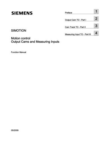
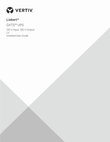
19.1 Bill of Materials19.1.1 Generating a Bill of MaterialsAltium Designer includes a powerful report generation engine, which can be used to generate acomprehensive Bill of Materials. Any schematic or PCB component property can be included. For components that link to acompany database, database fields that were not included in the schematic can also beincluded in the BOM. Enable the Show checkbox to include a component property. To includePCB parameters enable the Include Parameters from PCB option, to include additionaldatabase parameters enable the Include Parameters from Database option. The layout and grouping of data in the report is fully customizable, drag and drop columns tore-order them, drag component properties into the Grouped Columns region to group by thatproperty. Supported output formats include: text, CSV, XLS, HTML and XML. Excel (XLS) format output can auto load into your company Excel (XLT) spreadsheet. Report customization is remembered when you click OK to close the dialog. Click Export to generate the BOM in the selected File Format. Project and document parameters can also be included in the BOM. For example, to includethe value of the project parameter DesignRevision (added in the Project Options dialog) inthe exported BOM, add the string Field DesignRevision to the Excel template. The report generation engine can be accessed via the Reports » Bill of Materials menuentry (settings are saved in the project file), or via the Output Job editor (settings are saved inthe OutJob file). Choose one approach and use only that approach, since the settings of eachare stored separately.Figure 1. Configuring the layout of the Bill of Materials, then click Export to generate in the selected fileformat.Module 19: Output Generation and CAM File Editing19 - 1
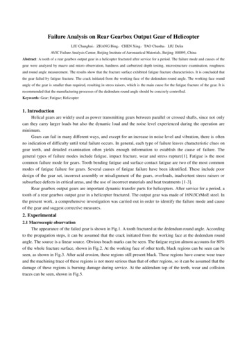
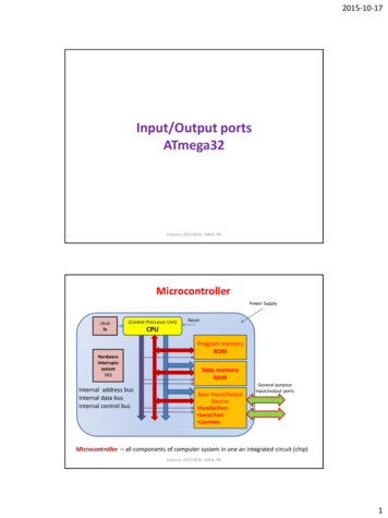
19.1.2 Using databases with the Bill of MaterialsUsing this method, the Database Link file (*.DBlink) defines linkage between the schematiccomponent and a matched record in a database. The record match is established by key fieldlinking, which can be a single key field (for example a part number), or multiple key fields (bydefining a Where clause).With this method of linking, the model and parameter information for the component must bepredefined as part of the Altium Designer library component. The library component must alsoinclude the necessary key field information as part of its definition. Once this has been definedyou add a database Link document (*.DBlink) to your Library Package or PCB project, then youcan synchronize the component information (parameters) with the contents of fields in thedatabase.Although each physical component defined by each database record does not need to map to aunique Altium Designer library component – many database components can share the samecomponent symbol – this method of linking would typically be used in a "one database record-toone Altium Designer component" fashion. The unique Altium Designer component can either bean instance placed on a schematic sheet, or a unique component in a component library.With DBLink-style database linking, you include the Database Link file with the project.19.1.3 Setting up the link to a databaseTo setup a link you’ll need to create a new *.DBlink file by going to File » New » Database LinkFile.Figure 2. A Database link file created for a project with all the links setupModule 19: Output Generation and CAM File Editing19 - 2
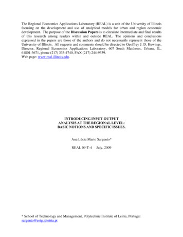
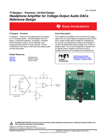
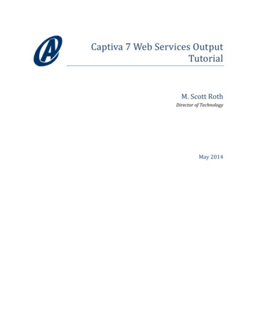
The first step is linking to the database itself.Figure 3. The database link setup.All Different types of databases can be linked to, including Excel, Access, SQL, MYSQL and evenOracle. Any database which provides OLE DB support can be connected to. In Figure 3 an ODBCbased connection string has been built using a datalink direct to an access database.For more details on all different types of connections to databases refer to the document AP0133Using Components Directly from Your Company Database.PDF which you can find in the helpdirectory of the Altium Designer installation, or on the Altium website.The next step is specifying a matching criteria.Figure 4. The matching criteriaIn Figure 4 the criteria is set to Manufacturer P/N for both database field and the part parameterfield. This means there needs to exist this parameter in both the database and on a createdcomponent were the original component came from, be that a schlib, integrated library or adatabase library. This field has to be a unique field that exists in both the database and on thecomponents being linked to.Once the look up key is set, there is also the field mapping to be setup.Figure 5. Field Mapping for each of the parameters that exists in the database.Module 19: Output Generation and CAM File Editing19 - 3
The first two columns (from the left) on the Field Mappings tab allow you to control whichinformation from the database is to be mapped to the component's models and parameters.The Database Field Name column lists all field (column) names in the currently active table ofthe database. The Design Parameter column defines how each corresponding field in thedatabase is to be used – whether it is used to source a schematic component, link-in a particularmodel, or to be attached to the component as a mapped design parameter.Initial mapping is performed automatically upon connection to the database, with all databasefields mapped.For fields that you explicitly do not want mapped from the database, set the Design Parameterentry to [None]. Unmapped database fields are distinguished on the tab by the use of a redcross icon. Mapped database fields are distinguished by a green tick icon.19.1.4 Linking the database to the Bill of MaterialSource information for a Bill of Materials (BOM) has, in the past, been taken from the parameterinformation of the placed components for the design. But that can lead to a lot of informationattached to a schematic that is only ever used for the BOM. If you place components from aDatabase Library the BOM Generator is able to extract any other record information that has notbeen added as design parameters at the time of placement.When configuring the Bill of Materials report using the Report Manager, simply enable theInclude Parameters from Database option. This option will only be available if one or morecomponents in your design are linked to an external database. In the parameter listing, theicon is used to distinguish a parameter that exists for one or more placed components in a linkedexternal database.Figure 6. Include additional component information that exists only in an external database19.1.5 Adding PCB Information Directly to a BOMSource information for a Bill of Materials (BOM) can be based on property information taken fromthe PCB in the event you need to customize and use the report generation for more than a BOM.Module 19: Output Generation and CAM File Editing19 - 4
An example would be for generation of a pick and place file where every placement machinewants the data (such as X, Y location) in a different column order and in different file formats.When configuring the Bill of Materials report using the Report Manager dialog, simply enable theInclude Parameters From PCB option. This option will only be available if there is a PCBdocument in the project file. In the parameter listing, the icon is used to distinguish a PCBparameter for one or more placed components in the project.Note that when you have a project with multiple PCBs and you enable the Include ParametersFrom PCB option, the BOM Report Options dialog will automatically prompt you to select whichPCB to include in the BOM report.Figure 7. Include additional component information that exists in a PCB.19.1.6 Supplier OptionsThis feature located in the bottom right side of the bill of materials dialog enables the use oflinking to direct supplier data that is already embedded in the design from suppliers such asDigikey, Farnell and Newark. In order for this section to function certain parameter need to exist inthe design. Supplier Unit PriceOnce this parameter has been enabled in the left column the supplier options should fully enable.Figure 8. Supplier options in the bill of materials.From here the local currency can be picked. There is two further options to pick, round upsupplier order Qty to cheaper price break. This tick box should pick the cheapest option forbuying in qty. For example if 9 are using on the design, however at 10 there is a price drop, andModule 19: Output Generation and CAM File Editing19 - 5
buying the extra is cheaper than the bill of material should round up to cheaper price point. Thesecond option, use cached pricing data in the parameters if offline is useful if the design inprogress uses a database library or you are offline, then it’ll use the data that is already cached inthe design, using the conversion rate done at the time of population of the parameter in thedesign.Note: The currency data is set in the pricing parameter. If there is a difference between thepricing data currency and local currency a conversion takes place.19.1.7 Exporting the ReportThe grid content of the data section can be exported and a report generated by using the Exportbutton in the R
the exported BOM, add the string Field DesignRevision to the Excel template. The report generation engine can be accessed via the Reports » Bill of Materials menu entry (settings are saved in the project file), or via the Output Job editor (settings are saved in the OutJob file). Choose one approach and use only that approach, since the settings of each are stored separately. Figure 1 .