Transcription
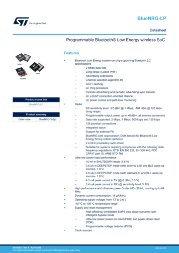
STM32MP157C/FArm dual Cortex -A7 800 MHz Cortex -M4 MPU, 3D GPU,TFT/DSI, 37 comm. interfaces, 29 timers, adv. analog, cryptoDatasheet - production dataFeaturesTFBGALFBGAIncludes ST state-of-the-art patentedtechnologyLFBGA448 (18 18mm)LFBGA354 (16 16mm)Pitch 0.8mmCore 32-bit dual-core Arm Cortex -A7– L1 32-Kbyte I / 32-Kbyte D for each core– 256-Kbyte unified level 2 cache– Arm NEON and Arm TrustZone 32-bit Arm Cortex -M4 with FPU/MPU– Up to 209 MHz (Up to 703 CoreMark )Memories External DDR memory up to 1 Gbyte– up to LPDDR2/LPDDR3-1066 16/32-bit– up to DDR3/DDR3L-1066 16/32-bit 708 Kbytes of internal SRAM: 256 Kbytes ofAXI SYSRAM 384 Kbytes of AHB SRAM 64 Kbytes of AHB SRAM in Backup domainand 4 Kbytes of SRAM in Backup domain Dual mode Quad-SPI memory interface Flexible external memory controller with up to16-bit data bus: parallel interface to connectexternal ICs and SLC NAND memories with upto 8-bit ECCSecurity/safety Secure boot, TrustZone peripherals, activetamper Cortex -M4 resources isolationReset and power management 1.71 V to 3.6 V I/Os supply (5 V-tolerant I/Os) POR, PDR, PVD and BOR On-chip LDOs (RETRAM, BKPSRAM, DSI1.2 V, USB 1.8 V, 1.1 V)TFBGA361 (12 12 mm)TFBGA257 (10 10 mm)min Pitch 0.5mm Internal temperature sensors Low-power modes: Sleep, Stop and Standby DDR memory retention in Standby mode Controls for PMIC companion chipLow-power consumption Total current consumption down to 2 µA(Standby mode, no RTC, no LSE, noBKPSRAM, no RETRAM)Clock management Internal oscillators: 64 MHz HSI oscillator,4 MHz CSI oscillator, 32 kHz LSI oscillator External oscillators: 8-48 MHz HSE oscillator,32.768 kHz LSE oscillator 6 PLLs with fractional modeGeneral-purpose input/outputs Up to 176 I/O ports with interrupt capability– Up to 8 secure I/Os– Up to 6 Wakeup, 3 tampers, 1 activetamperInterconnect matrix 2 bus matrices– 64-bit Arm AMBA AXI interconnect, up to266 MHz– 32-bit Arm AMBA AHB interconnect, upto 209 MHz3 DMA controllers to unload the CPU 48 physical channels in total Backup regulator ( 0.9 V)March 2022This is information on a product in full production.DS12505 Rev 71/262www.st.com
STM32MP157C/F 1 high-speed general-purpose master directmemory access controller (MDMA) 2 dual-port DMAs with FIFO and requestrouter capabilities for optimal peripheralmanagementUp to 37 communication peripherals– up to WXGA (1366 768) @60 fps or up toFull HD (1920 1080) @30 fps– Pixel clock up to 90 MHz– Two layers with programmable colour LUT MIPI DSI 2 data lanes up to 1 Gbps eachUp to 29 timers and 3 watchdogs2 6 I C FM (1 Mbit/s, SMBus/PMBus) 4 UART 4 USART (12.5 Mbit/s, ISO7816interface, LIN, IrDA, SPI slave) 6 SPI (50 Mbit/s, including 3 with full duplexI2S audio class accuracy via internal audio PLLor external clock) 4 SAI (stereo audio: I2S, PDM, SPDIF Tx) SPDIF Rx with 4 inputs 2 32-bit timers with up to 4 IC/OC/PWM orpulse counter and quadrature (incremental)encoder input 2 16-bit advanced motor control timers 10 16-bit general-purpose timers (including 2basic timers without PWM) 5 16-bit low-power timers RTC with sub-second accuracy and hardwarecalendar HDMI-CEC interface MDIO Slave interface 3 SDMMC up to 8-bit (SD / e MMC / SDIO) 2 CAN controllers supporting CAN FDprotocol, out of which one supports timetriggered CAN (TTCAN) 2 4 Cortex -A7 system timers (secure, nonsecure, virtual, hypervisor) 1 SysTick M4 timer 3 watchdogs (2 independent and window) 2 USB 2.0 high-speed Host 1 USB 2.0 full-speed OTG simultaneously– or 1 USB 2.0 high-speed Host 1 USB 2.0 high-speed OTGsimultaneously 10/100M or Gigabit Ethernet GMAC– IEEE 1588v2 hardware,MII/RMII/GMII/RGMIIHardware acceleration AES 128, 192, 256, TDES HASH (MD5, SHA-1, SHA224, SHA256),HMAC 2 true random number generator(3 oscillators each) 2 CRC calculation unit 8- to 14-bit camera interface up to 140 Mbyte/sDebug mode6 analog peripherals Arm CoreSight trace and debug: SWD andJTAG interfaces 2 ADCs with 16-bit max. resolution (12 bitsup to 4.5 Msps, 14 bits up to 4 Msps, 16 bits upto 3.6 Msps) 1 temperature sensor 2 12-bit D/A converters (1 MHz) 1 digital filters for sigma delta modulator(DFSDM) with 8 channels/6 filters 8-Kbyte embedded trace buffer3072-bit fuses including 96-bit unique ID,up to 1184-bit available for userAll packages are ECOPACK2 compliant Internal or external ADC/DAC reference VREF Graphics 3D GPU: Vivante - OpenGL ES 2.0– Up to 26 Mtriangle/s, 133 Mpixel/s LCD-TFT controller, up to 24-bit // RGB8882/262DS12505 Rev 7
STM32MP157C/FContentsContents1Introduction . . . . . . . . . . . . . . . . . . . . . . . . . . . . . . . . . . . . . . . . . . . . . . . 132Description . . . . . . . . . . . . . . . . . . . . . . . . . . . . . . . . . . . . . . . . . . . . . . . . 143Functional overview . . . . . . . . . . . . . . . . . . . . . . . . . . . . . . . . . . . . . . . . 213.1Dual-core Arm Cortex -A7 subsystem . . . . . . . . . . . . . . . . . . . . . . . . . . 213.1.1Features . . . . . . . . . . . . . . . . . . . . . . . . . . . . . . . . . . . . . . . . . . . . . . . . . 213.1.2Overview . . . . . . . . . . . . . . . . . . . . . . . . . . . . . . . . . . . . . . . . . . . . . . . . 213.2Arm Cortex -M4 with FPU . . . . . . . . . . . . . . . . . . . . . . . . . . . . . . . . . . . 233.3Graphic processing unit (GPU) . . . . . . . . . . . . . . . . . . . . . . . . . . . . . . . . 233.4Memories . . . . . . . . . . . . . . . . . . . . . . . . . . . . . . . . . . . . . . . . . . . . . . . . . 253.4.1External SDRAM . . . . . . . . . . . . . . . . . . . . . . . . . . . . . . . . . . . . . . . . . . 253.4.2Embedded SRAM . . . . . . . . . . . . . . . . . . . . . . . . . . . . . . . . . . . . . . . . . 253.5DDR3/DDR3L/LPDDR2/LPDDR3 controller (DDRCTRL) . . . . . . . . . . . . 263.6TrustZone address space controller for DDR (TZC) . . . . . . . . . . . . . . . . 273.7Boot modes . . . . . . . . . . . . . . . . . . . . . . . . . . . . . . . . . . . . . . . . . . . . . . . 283.8Power supply management . . . . . . . . . . . . . . . . . . . . . . . . . . . . . . . . . . . 293.8.1Power supply scheme . . . . . . . . . . . . . . . . . . . . . . . . . . . . . . . . . . . . . . 293.8.2Power supply supervisor . . . . . . . . . . . . . . . . . . . . . . . . . . . . . . . . . . . . 313.9Low-power strategy . . . . . . . . . . . . . . . . . . . . . . . . . . . . . . . . . . . . . . . . . 323.10Reset and clock controller (RCC) . . . . . . . . . . . . . . . . . . . . . . . . . . . . . . . 333.10.1Clock management . . . . . . . . . . . . . . . . . . . . . . . . . . . . . . . . . . . . . . . . 333.10.2System reset sources . . . . . . . . . . . . . . . . . . . . . . . . . . . . . . . . . . . . . . 343.11Hardware semaphore (HSEM) . . . . . . . . . . . . . . . . . . . . . . . . . . . . . . . . . 343.12Inter-processor communication controller (IPCC) . . . . . . . . . . . . . . . . . . 343.12.1IPCC main features . . . . . . . . . . . . . . . . . . . . . . . . . . . . . . . . . . . . . . . . 353.13General-purpose input/outputs (GPIOs) . . . . . . . . . . . . . . . . . . . . . . . . . . 353.14TrustZone protection controller (ETZPC) . . . . . . . . . . . . . . . . . . . . . . . . . 353.15Bus-interconnect matrix . . . . . . . . . . . . . . . . . . . . . . . . . . . . . . . . . . . . . . 363.16DMA controllers . . . . . . . . . . . . . . . . . . . . . . . . . . . . . . . . . . . . . . . . . . . . 383.17Nested vectored interrupt controller (NVIC) . . . . . . . . . . . . . . . . . . . . . . . 383.18Extended interrupt and event controller (EXTI) . . . . . . . . . . . . . . . . . . . . 38DS12505 Rev 73/2627
Contents4/262STM32MP157C/F3.19Cyclic redundancy check calculation unit (CRC1, CRC2) . . . . . . . . . . . . 393.20Flexible memory controller (FMC) . . . . . . . . . . . . . . . . . . . . . . . . . . . . . . 393.21Dual Quad-SPI memory interface (QUADSPI) . . . . . . . . . . . . . . . . . . . . . 393.22Analog-to-digital converters (ADCs) . . . . . . . . . . . . . . . . . . . . . . . . . . . . . 403.23Temperature sensor . . . . . . . . . . . . . . . . . . . . . . . . . . . . . . . . . . . . . . . . . 403.24Digital temperature sensor (DTS) . . . . . . . . . . . . . . . . . . . . . . . . . . . . . . . 403.25VBAT operation . . . . . . . . . . . . . . . . . . . . . . . . . . . . . . . . . . . . . . . . . . . . . 403.26Digital-to-analog converters (DAC1, DAC2) . . . . . . . . . . . . . . . . . . . . . . . 413.27Voltage reference buffer (VREFBUF) . . . . . . . . . . . . . . . . . . . . . . . . . . . . 423.28Digital filter for sigma delta modulators (DFSDM1) . . . . . . . . . . . . . . . . . 423.29Digital camera interface (DCMI) . . . . . . . . . . . . . . . . . . . . . . . . . . . . . . . . 443.30LCD-TFT display controller (LTDC) . . . . . . . . . . . . . . . . . . . . . . . . . . . . . 443.31Display serial interface (DSI) . . . . . . . . . . . . . . . . . . . . . . . . . . . . . . . . . . 453.32True random number generator (RNG1, RNG2) . . . . . . . . . . . . . . . . . . . 453.33Cryptographic and hash processors (CRYP1, CRYP2 andHASH1, HASH2) . . . . . . . . . . . . . . . . . . . . . . . . . . . . . . . . . . . . . . . . . . . 463.34Boot and security and OTP control (BSEC) . . . . . . . . . . . . . . . . . . . . . . . 463.35Timers and watchdogs . . . . . . . . . . . . . . . . . . . . . . . . . . . . . . . . . . . . . . . 463.35.1Advanced-control timers (TIM1, TIM8) . . . . . . . . . . . . . . . . . . . . . . . . . 483.35.2General-purpose timers (TIM2, TIM3, TIM4, TIM5, TIM12, TIM13,TIM14, TIM15, TIM16, TIM17) . . . . . . . . . . . . . . . . . . . . . . . . . . . . . . . . 483.35.3Basic timers TIM6 and TIM7 . . . . . . . . . . . . . . . . . . . . . . . . . . . . . . . . . 493.35.4Low-power timer (LPTIM1, LPTIM2, LPTIM3, LPTIM4, LPTIM5) . . . . . 493.35.5Independent watchdog (IWDG1, IWDG2) . . . . . . . . . . . . . . . . . . . . . . . 493.35.6System window watchdog (WWDG1) . . . . . . . . . . . . . . . . . . . . . . . . . . 493.35.7SysTick timer (Cortex-M4) . . . . . . . . . . . . . . . . . . . . . . . . . . . . . . . . . . . 493.35.8Generic timers (Cortex-A7 CNT) . . . . . . . . . . . . . . . . . . . . . . . . . . . . . . 503.36System timer generation (STGEN) . . . . . . . . . . . . . . . . . . . . . . . . . . . . . . 503.37Real-time clock (RTC) . . . . . . . . . . . . . . . . . . . . . . . . . . . . . . . . . . . . . . . 503.38Tamper and backup registers (TAMP) . . . . . . . . . . . . . . . . . . . . . . . . . . . 513.39Inter-integrated circuit interface (I2C1, I2C2, I2C3, I2C4, I2C5, I2C6) . . . 533.40Universal synchronous asynchronous receiver transmitter(USART1, USART2, USART3, USART6 and UART4, UART5,UART7, UART8) . . . . . . . . . . . . . . . . . . . . . . . . . . . . . . . . . . . . . . . . . . . . 533.41Serial peripheral interface (SPI1, SPI2, SPI3, SPI4, SPI5,SPI6)– inter- integrated sound interfaces (I2S1, I2S2, I2S3) . . . . . . . . . . 54DS12505 Rev 7
STM32MP157C/FContents3.42Serial audio interfaces (SAI1, SAI2, SAI3, SAI4) . . . . . . . . . . . . . . . . . . . 553.43SPDIF receiver interface (SPDIFRX) . . . . . . . . . . . . . . . . . . . . . . . . . . . . 553.44Management data input/output (MDIOS) . . . . . . . . . . . . . . . . . . . . . . . . . 563.45Secure digital input/output MultiMediaCard interface(SDMMC1, SDMMC2, SDMMC3) . . . . . . . . . . . . . . . . . . . . . . . . . . . . . . 563.46Controller area network (FDCAN1, FDCAN2) . . . . . . . . . . . . . . . . . . . . . 563.47Universal serial bus high-speed host (USBH) . . . . . . . . . . . . . . . . . . . . . 573.48USB on-the-go high-speed (OTG) . . . . . . . . . . . . . . . . . . . . . . . . . . . . . . 573.49Gigabit Ethernet MAC interface (ETH1) . . . . . . . . . . . . . . . . . . . . . . . . . . 583.50High-definition multimedia interface (HDMI) – Consumerelectronics control (CEC) . . . . . . . . . . . . . . . . . . . . . . . . . . . . . . . . . . . . . 593.51Debug infrastructure . . . . . . . . . . . . . . . . . . . . . . . . . . . . . . . . . . . . . . . . . 594Pinouts, pin description and alternate functions . . . . . . . . . . . . . . . . . 605Memory mapping . . . . . . . . . . . . . . . . . . . . . . . . . . . . . . . . . . . . . . . . . . 1226Electrical characteristics . . . . . . . . . . . . . . . . . . . . . . . . . . . . . . . . . . . 1236.1Parameter conditions . . . . . . . . . . . . . . . . . . . . . . . . . . . . . . . . . . . . . . . 1236.1.1Minimum and maximum values . . . . . . . . . . . . . . . . . . . . . . . . . . . . . . 1236.1.2Typical values . . . . . . . . . . . . . . . . . . . . . . . . . . . . . . . . . . . . . . . . . . . 1236.1.3Typical curves . . . . . . . . . . . . . . . . . . . . . . . . . . . . . . . . . . . . . . . . . . . 1236.1.4Loading capacitor . . . . . . . . . . . . . . . . . . . . . . . . . . . . . . . . . . . . . . . . 1236.1.5Pin input voltage . . . . . . . . . . . . . . . . . . . . . . . . . . . . . . . . . . . . . . . . . 1236.1.6Power supply scheme . . . . . . . . . . . . . . . . . . . . . . . . . . . . . . . . . . . . . 1246.1.7Current consumption measurement . . . . . . . . . . . . . . . . . . . . . . . . . . 1256.2Absolute maximum ratings . . . . . . . . . . . . . . . . . . . . . . . . . . . . . . . . . . . 1256.3Operating conditions . . . . . . . . . . . . . . . . . . . . . . . . . . . . . . . . . . . . . . . 1276.3.1General operating conditions . . . . . . . . . . . . . . . . . . . . . . . . . . . . . . . . 1276.3.2Operating conditions at power-up / power-down . . . . . . . . . . . . . . . . . 1296.3.3Embedded reset and power control block characteristics . . . . . . . . . . 1316.3.4Embedded reference voltage . . . . . . . . . . . . . . . . . . . . . . . . . . . . . . . . 1336.3.5Embedded regulators characteristics . . . . . . . . . . . . . . . . . . . . . . . . . 1346.3.6Supply current characteristics . . . . . . . . . . . . . . . . . . . . . . . . . . . . . . . 1366.3.7Wakeup time from low-power modes . . . . . . . . . . . . . . . . . . . . . . . . . . 1476.3.8External clock source characteristics . . . . . . . . . . . . . . . . . . . . . . . . . . 149DS12505 Rev 75/2627
Contents76/262STM32MP157C/F6.3.9External clock source security characteristics . . . . . . . . . . . . . . . . . . . 1556.3.10Internal clock source characteristics . . . . . . . . . . . . . . . . . . . . . . . . . . 1556.3.11PLL characteristics . . . . . . . . . . . . . . . . . . . . . . . . . . . . . . . . . . . . . . . . 1566.3.12PLL spread spectrum clock generation (SSCG) characteristics . . . . . 1616.3.13Memory characteristics . . . . . . . . . . . . . . . . . . . . . . . . . . . . . . . . . . . . 1626.3.14EMC characteristics . . . . . . . . . . . . . . . . . . . . . . . . . . . . . . . . . . . . . . . 1646.3.15Absolute maximum ratings (electrical sensitivity) . . . . . . . . . . . . . . . . 1656.3.16I/O current injection characteristics . . . . . . . . . . . . . . . . . . . . . . . . . . . 1666.3.17I/O port characteristics . . . . . . . . . . . . . . . . . . . . . . . . . . . . . . . . . . . . . 1666.3.18NRST and NRST CORE pin characteristics . . . . . . . . . . . . . . . . . . . . 1756.3.19FMC characteristics . . . . . . . . . . . . . . . . . . . . . . . . . . . . . . . . . . . . . . . 1766.3.20QUADSPI interface characteristics . . . . . . . . . . . . . . . . . . . . . . . . . . . 1936.3.21Delay block (DLYB) characteristics . . . . . . . . . . . . . . . . . . . . . . . . . . . 1956.3.2216-bit ADC characteristics . . . . . . . . . . . . . . . . . . . . . . . . . . . . . . . . . . 1956.3.23DAC electrical characteristics . . . . . . . . . . . . . . . . . . . . . . . . . . . . . . . 2046.3.24Voltage reference buffer characteristics . . . . . . . . . . . . . . . . . . . . . . . 2076.3.25Temperature sensor characteristics . . . . . . . . . . . . . . . . . . . . . . . . . . . 2096.3.26DTS characteristics . . . . . . . . . . . . . . . . . . . . . . . . . . . . . . . . . . . . . . . 2096.3.27VBAT ADC monitoring characteristics and charging characteristics . . 2106.3.28Temperature and VBAT monitoring characteristics fortamper detection . . . . . . . . . . . . . . . . . . . . . . . . . . . . . . . . . . . . . . . . . 2106.3.29VDDCORE monitoring characteristics . . . . . . . . . . . . . . . . . . . . . . . . . 2116.3.30Voltage booster for analog switch . . . . . . . . . . . . . . . . . . . . . . . . . . . . 2116.3.31Compensation cell . . . . . . . . . . . . . . . . . . . . . . . . . . . . . . . . . . . . . . . . 2116.3.32Digital filter for sigma-delta modulators (DFSDM) characteristics . . . . 2116.3.33Camera interface (DCMI) characteristics . . . . . . . . . . . . . . . . . . . . . . . 2146.3.34LCD-TFT controller (LTDC) characteristics . . . . . . . . . . . . . . . . . . . . . 2156.3.35Timer characteristics . . . . . . . . . . . . . . . . . . . . . . . . . . . . . . . . . . . . . . 2176.3.36Communications interfaces . . . . . . . . . . . . . . . . . . . . . . . . . . . . . . . . . 2176.3.37USART interface characteristics . . . . . . . . . . . . . . . . . . . . . . . . . . . . . 2346.3.38USB High-Speed PHY characteristics . . . . . . . . . . . . . . . . . . . . . . . . . 2366.3.39DSI PHY characteristics . . . . . . . . . . . . . . . . . . . . . . . . . . . . . . . . . . . 2376.3.40JTAG/SWD interface characteristics . . . . . . . . . . . . . . . . . . . . . . . . . . 237Package information . . . . . . . . . . . . . . . . . . . . . . . . . . . . . . . . . . . . . . . 2407.1TFBGA257 package information . . . . . . . . . . . . . . . . . . . . . . . . . . . . . . 2407.2LFBGA354 package information . . . . . . . . . . . . . . . . . . . . . . . . . . . . . . 244DS12505 Rev 7
STM32MP157C/FContents7.3TFBA361 package information . . . . . . . . . . . . . . . . . . . . . . . . . . . . . . . . 2477.4LFBGA448 package information . . . . . . . . . . . . . . . . . . . . . . . . . . . . . . 2517.5Thermal characteristics . . . . . . . . . . . . . . . . . . . . . . . . . . . . . . . . . . . . . 2547.5.1Reference documents . . . . . . . . . . . . . . . . . . . . . . . . . . . . . . . . . . . . . 2558Ordering information . . . . . . . . . . . . . . . . . . . . . . . . . . . . . . . . . . . . . . 2569Revision history . . . . . . . . . . . . . . . . . . . . . . . . . . . . . . . . . . . . . . . . . . 257DS12505 Rev 77/2627
List of tablesSTM32MP157C/FList of tablesTable 1.Table 2.Table 3.Table 4.Table 5.Table 6.Table 7.Table 8.Table 9.Table 10.Table 11.Table 12.Table 13.Table 14.Table 15.Table 16.Table 17.Table 18.Table 19.Table 20.Table 21.Table 22.Table 23.Table 24.Table 25.Table 26.Table 27.Table 28.Table 29.Table 30.Table 31.Table 32.Table 33.Table 34.Table 35.Table 36.Table 37.Table 38.Table 39.Table 40.Table 41.Table 42.Table 43.Table 44.Table 45.8/262STM32MP157C/F features and peripheral counts . . . . . . . . . . . . . . . . . . . . . . . . . . . . . . . 16Boot modes. . . . . . . . . . . . . . . . . . . . . . . . . . . . . . . . . . . . . . . . . . . . . . . . . . . . . . . . . . . . . 28System versus domain power mode. . . . . . . . . . . . . . . . . . . . . . . . . . . . . . . . . . . . . . . . . . 32Timer feature comparison . . . . . . . . . . . . . . . . . . . . . . . . . . . . . . . . . . . . . . . . . . . . . . . . . . 47USART features . . . . . . . . . . . . . . . . . . . . . . . . . . . . . . . . . . . . . . . . . . . . . . . . . . . . . . . . . 54Legend/abbreviations used in the pinout table . . . . . . . . . . . . . . . . . . . . . . . . . . . . . . . . . . 64STM32MP157C/F pin and ball definitions . . . . . . . . . . . . . . . . . . . . . . . . . . . . . . . . . . . . . 65Alternate function AF0 to AF7. . . . . . . . . . . . . . . . . . . . . . . . . . . . . . . . . . . . . . . . . . . . . . . 93Alternate function AF8 to AF15. . . . . . . . . . . . . . . . . . . . . . . . . . . . . . . . . . . . . . . . . . . . . 105Voltage characteristics . . . . . . . . . . . . . . . . . . . . . . . . . . . . . . . . . . . . . . . . . . . . . . . . . . . 125Current characteristics . . . . . . . . . . . . . . . . . . . . . . . . . . . . . . . . . . . . . . . . . . . . . . . . . . . 126Thermal characteristics. . . . . . . . . . . . . . . . . . . . . . . . . . . . . . . . . . . . . . . . . . . . . . . . . . . 127General operating conditions . . . . . . . . . . . . . . . . . . . . . . . . . . . . . . . . . . . . . . . . . . . . . . 127Operating conditions at power-up / power-down . . . . . . . . . . . . . . . . . . . . . . . . . . . . . . . 130Embedded reset and power control block characteristics. . . . . . . . . . . . . . . . . . . . . . . . . 131Embedded reference voltage . . . . . . . . . . . . . . . . . . . . . . . . . . . . . . . . . . . . . . . . . . . . . . 133Embedded reference voltage calibration value. . . . . . . . . . . . . . . . . . . . . . . . . . . . . . . . . 134REG1V1 embedded regulator (USB PHY) characteristics . . . . . . . . . . . . . . . . . . . . . . . 134REG1V2 embedded regulator (DSI) characteristics . . . . . . . . . . . . . . . . . . . . . . . . . . . . . 135REG1V8 embedded regulator (USB DSI) characteristics . . . . . . . . . . . . . . . . . . . . . . . . 135Current consumption (IDDCORE) in Run mode . . . . . . . . . . . . . . . . . . . . . . . . . . . . . . . . 137Current consumption (IDD) in Run mode . . . . . . . . . . . . . . . . . . . . . . . . . . . . . . . . . . . . . 142Current consumption in Stop mode . . . . . . . . . . . . . . . . . . . . . . . . . . . . . . . . . . . . . . . . . 142Current consumption in LPLV-Stop mode . . . . . . . . . . . . . . . . . . . . . . . . . . . . . . . . . . . . 143Current consumption in Standby mode . . . . . . . . . . . . . . . . . . . . . . . . . . . . . . . . . . . . . . 144Current consumption in VBAT mode . . . . . . . . . . . . . . . . . . . . . . . . . . . . . . . . . . . . . . . . 145Low-power mode wakeup timings . . . . . . . . . . . . . . . . . . . . . . . . . . . . . . . . . . . . . . . . . . 148Wakeup time using USART . . . . . . . . . . . . . . . . . . . . . . . . . . . . . . . . . . . . . . . . . . . . . . . 148High-speed external user clock characteristics(digital bypass) . . . . . . . . . . . . . . . . . . . . . . . . . . . . . . . . . . . . . . . . . . . . . . . . . . . . . . . . . 149High-speed external user clock characteristics(analog bypass) . . . . . . . . . . . . . . . . . . . . . . . . . . . . . . . . . . . . . . . . . . . . . . . . . . . . . . . . 149Low-speed external user clock characteristics(analog bypass) . . . . . . . . . . . . . . . . . . . . . . . . . . . . . . . . . . . . . . . . . . . . . . . . . . . . . . . . 150Low-speed external user clock characteristics (digital bypass) . . . . . . . . . . . . . . . . . . . . 1518-48 MHz HSE oscillator characteristics . . . . . . . . . . . . . . . . . . . . . . . . . . . . . . . . . . . . . 152Low-speed external user clock characteristics . . . . . . . . . . . . . . . . . . . . . . . . . . . . . . . . . 154High-speed external user clock security system (HSE CSS) . . . . . . . . . . . . . . . . . . . . . . 155HSI oscillator characteristics. . . . . . . . . . . . . . . . . . . . . . . . . . . . . . . . . . . . . . . . . . . . . . . 155CSI oscillator characteristics. . . . . . . . . . . . . . . . . . . . . . . . . . . . . . . . . . . . . . . . . . . . . . . 156LSI oscillator characteristics . . . . . . . . . . . . . . . . . . . . . . . . . . . . . . . . . . . . . . . . . . . . . . . 156PLL1 1600, PLL2 1600 characteristics . . . . . . . . . . . . . . . . . . . . . . . . . . . . . . . . . . . . . . 157PLL3 800, PLL4 800 characteristics . . . . . . . . . . . . . . . . . . . . . . . . . . . . . . . . . . . . . . . . 158USB PLL characteristics . . . . . . . . . . . . . . . . . . . . . . . . . . . . . . . . . . . . . . . . . . . . . . . . . 160DSI PLL characteristics . . . . . . . . . . . . . . . . . . . . . . . . . . . . . . . . . . . . . . . . . . . . . . . . . . 160SSCG parameters constraint . . . . . . . . . . . . . . . . . . . . . . . . . . . . . . . . . . . . . . . . . . . . . . 161OTP characteristics . . . . . . . . . . . . . . . . . . . . . . . . . . . . . . . . . . . . . . . . . . . . . . . . . . . . . 162DC specifications – DDR3 or DDR3L mode . . . . . . . . . . . . . . . . . . . . . . . . . . . . . . . . . . . 163DS12505 Rev 7
STM32MP157C/FTable 46.Table 47.Table 48.Table 49.Table 50.Table 51.Table 52.Table 53.Table 54.Table 55.Table 56.Table 57.Table 58.Table 59.Table 60.Table 61.Table 62.Table 63.Table 64.Table 65.Table 66.Table 67.Table 68.Table 69.Table 70.Table 71.Table 72.Table 73.Table 74.Table 75.Table 76.Table 77.Table 78.Table 79.Table 80.Table 81.Table 82.Table 83.Table 84.Table 85.Table 86.Table 87.Table 88.Table 89.Table 90.Table 91.Table 92.Table 93.Table 94.Table 95.Table 96.List of tablesDC specifications – LPDDR2 or LPDDR3 mode. . . . . . . . . . . . . . . . . . . . . . . . . . . . . . . . 163EMS characteristics . . . . . . . . . . . . . . . . . . . . . . . . . . . . . . . . . . . . . . . . . . . . . . . . . . . . . 164EMI characteristics . . . . . . . . . . . . . . . . . . . . . . . . . . . . . . . . . . . . . . . . . . . . . . . . . . . . . . 165ESD absolute maximum ratings . . . . . . . . . . . . . . . . . . . . . . . . . . . . . . . . . . . . . . . . . . . . 165Electrical sensitivities . . . . . . . . . . . . . . . . . . . . . . . . . . . . . . . . . . . . . . . . . . . . . . . . . . . . 166I/O current injection susceptibility . . . . . . . . . . . . . . . . . . . . . . . . . . . . . . . . . . . . . . . . . . . 166I/O static characteristics . . . . . . . . . . . . . . . . . . . . . . . . . . . . . . . . . . . . . . . . . . . . . . . . . . 167Output voltage characteristics for all I/Os except PC13, PC14, PC15 and PI8 . . . . . . . . 169Output voltage characteristics for PC13, PC14, PC15 and PI8 . . . . . . . . . . . . . . . . . . . . 170Output timing characteristics (HSLV OFF) . . . . . . . . . . . . . . . . . . . . . . . . . . . . . . . . . . . . 171Output timing characteristics (HSLV ON, h IO structure) . . . . . . . . . . . . . . . . . . . . . . . . 173Output timing characteristics (HSLV ON, vh IO structure) . . . . . . . . . . . . . . . . . . . . . . . 174NRST and NRST CORE pin characteristics . . . . . . . . . . . . . . . . . . . . . . . . . . . . . . . . . . 176Asynchronous non-multiplexed SRAM/PSRAM/NOR read timings . . . . . . . . . . . . . . . . . 178Asynchronous non-multiplexed SRAM/PSRAM/NOR read - NWAIT timings . . . . . . . . . . 178Asynchronous non-multiplexed SRAM/PSRAM/NOR write timings . . . . . . . . . . . . . . . . . 179Asynchronous non-multiplexed SRAM/PSRAM/NOR write - NWAIT timings. . . . . . . . . . 180Asynchronous multiplexed PSRAM/NOR read timings. . . . . . . . . . . . . . . . . . . . . . . . . . . 181Asynchronous multiplexed PSRAM/NOR read-NWAIT timings . . . . . . . . . . . . . . . . . . . . 181Asynchronous multiplexed PSRAM/NOR write timings . . . . . . . . . . . . . . . . . . . . . . . . . . 183Asynchronous multiplexed PSRAM/NOR write-NWAIT timings . . . . . . . . . . . . . . . . . . . . 183Synchronous multiplexed NOR/PSRAM read timings . . . . . . . . . . . . . . . . . . . . . . . . . . . 185Synchronous multiplexed PSRAM write timings . . . . . . . . . . . . . . . . . . . . . . . . . . . . . . . . 187Synchronous non-multiplexed NOR/PSRAM read timings . . . . . . . . . . . . . . . . . . . . . . . . 188Synchronous non-multiplexed PSRAM write timings . . . . . . . . . . . . . . . . . . . . . . . . . . . . 190Switching characteristics for NAND Flash read cycles . . . . . . . . . . . . . . . . . . . . . . . . . . . 192Switching characteristics for NAND Flash write cycles. . . . . . . . . . . . . . . . . . . . . . . . . . . 193QUADSPI characteristics in SDR mode . . . . . . . . . . . . . . . . . . . . . . . . . . . . . . . . . . . . . . 193QUADSPI characteristics in DDR mode . . . . . . . . . . . . . . . . . . . . . . . . . . . . . . . . . . . . . . 194Dynamics characteristics: Delay block characteristics . . . . . . . . . . . . . . . . . . . . . . . . . . . 195ADC characteristics . . . . . . . . . . . . . . . . . . . . . . . . . . . . . . . . . . . . . . . . . . . . . . . . . . . . . 195Minimum sampling time versus RAIN with 47 pF PCB capacitorup to 125 C and VDDA 1.6 V . . . . . . . . . . . . . . . . . . . . . . . . . . . . . . . . . . . . . . . . . . . . 198ADC accuracy . . . . . . . . . . . . . . . . . . . . . . . . . . . . . . . . . . . . . . . . . . . . . . . . . . . . . . . . . . 200Minimum delay for interleaved conversion versus resolution . . . . . . . . . . . . . . . . . . . . . . 201DAC characteristics . . . . . . . . . . . . . . . . . . . . . . . . . . . . . . . . . . . . . . . . . . . . . . . . . . . . . 204DAC accuracy . . . . . . . . . . . . . . . . . . . . . . . . . . . . . . . . . . . . . . . . . . . . . . . . . . . . . . . . . . 206VREFBUF characteristics . . . . . . . . . . . . . . . . . . . . . . . . . . . . . . . . . . . . . . . . . . . . . . . . . 207Temperature sensor characteristics . . . . . . . . . . . . . . . . . . . . . . . . . . . . . . . . . . . . . . . . . 209Temperature sensor calibration values. . . . . . . . . . . . . . . . . . . . . . . . . . . . . . . . . . . . . . . 209DTS characteristics. . . . . . . . . . . . . . . . . . . . . . . . . . . . . . . . . . . . . . . . . . . . . . . . . . . . . . 209VBAT ADC monitoring characteristics . . . . . . . . . . . . . . . . . . . . . . . . . . . . . . . . . . . . . . . . 210VBAT charging characteristics . . . . . . . . . . . . . . . . . . . . . . . . . . . . . . . . . . . . . . . . . . . . . . 210Temperature and VBAT monitoring characteristics for temper detection . . . . . . . . . . . . . 210VDDCORE monitoring characteristics . . . . . . . . . . . . . . . . . . . . . . . . . . . . . . . . . . . . . . . . . 211Voltage booster for analog switch characteristics. . . . . . . . . . . . . . . . .
64 Kbytes of AHB SRAM in Backup domain and 4 Kbytes of SRAM in Backup domain Dual mode Quad-SPI memory interface Flexible external memory controller with up to 16-bit data bus: parallel interface to connect external ICs and SLC NAND memories with up to 8-bit ECC Security/safety Secure boot, TrustZone peripherals, active tamper