Transcription
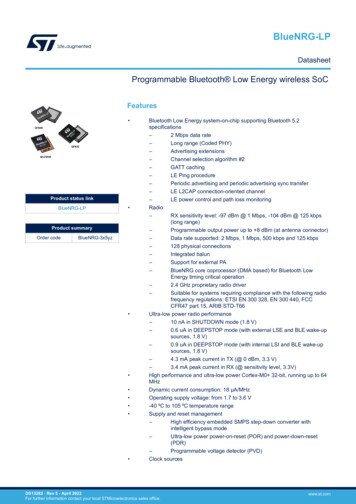
BlueNRG-LPDatasheetProgrammable Bluetooth Low Energy wireless SoCFeatures Product status linkBlueNRG-LP Product summaryOrder codeBlueNRG-3x5yz Bluetooth Low Energy system-on-chip supporting Bluetooth 5.2specifications–2 Mbps data rate–Long range (Coded PHY)–Advertising extensions–Channel selection algorithm #2–GATT caching–LE Ping procedure–Periodic advertising and periodic advertising sync transfer–LE L2CAP connection-oriented channel–LE power control and path loss monitoringRadio–RX sensitivity level: -97 dBm @ 1 Mbps, -104 dBm @ 125 kbps(long range)–Programmable output power up to 8 dBm (at antenna connector)–Data rate supported: 2 Mbps, 1 Mbps, 500 kbps and 125 kbps–128 physical connections–Integrated balun–Support for external PA–BlueNRG core coprocessor (DMA based) for Bluetooth LowEnergy timing critical operation–2.4 GHz proprietary radio driver–Suitable for systems requiring compliance with the following radiofrequency regulations: ETSI EN 300 328, EN 300 440, FCCCFR47 part 15, ARIB STD-T66Ultra-low power radio performance–10 nA in SHUTDOWN mode (1.8 V)–0.6 uA in DEEPSTOP mode (with external LSE and BLE wake-upsources, 1.8 V)–0.9 uA in DEEPSTOP mode (with internal LSI and BLE wake-upsources, 1.8 V)–4.3 mA peak current in TX (@ 0 dBm, 3.3 V)–3.4 mA peak current in RX (@ sensitivity level, 3.3V)High performance and ultra-low power Cortex-M0 32-bit, running up to 64MHzDynamic current consumption: 18 µA/MHzOperating supply voltage: from 1.7 to 3.6 V-40 ºC to 105 ºC temperature rangeSupply and reset management–High efficiency embedded SMPS step-down converter withintelligent bypass mode–Ultra-low power power-on-reset (POR) and power-down-reset(PDR)–Programmable voltage detector (PVD)Clock sourcesDS13282 - Rev 5 - April 2022For further information contact your local STMicroelectronics sales office.www.st.com
BlueNRG-LP –Fail safe 32 MHz crystal oscillator with integrated trimming capacitors–32 kHz crystal oscillatorInternal low-power 32 kHz RO–On-chip non-volatile Flash memory of 256 kBOn-chip RAM of 64 kB or 32 kBOne-time-programmable (OTP) memory area of 1 kBEmbedded UART bootloaderUltra-low power modes with or without timer and RAM retentionQuadrature decoderEnhanced security mechanisms such as:–Flash read/write protection–SWD disabling–Secure bootloaderSecurity features–True random number generator (RNG)–Hardware encryption AES maximum 128-bit security co-processor–HW public key accelerator (PKA)–CRC calculation unit–64-bit unique IDSystem peripherals–1x DMA controller with 8 channels supporting ADC, SPI, I2C, USART and LPUART–1x SPI–2x SPI/I2S–2x I2C (SMBus/PMBus)–1x PDM (digital microphone interface)–1x LPUART–1x USART (ISO 7816 smartcard mode, IrDA, SPI Master and Modbus)–1x independent WDG–1x real time clock (RTC)–1x independent SysTick–1x 16-bit, 6 channel advanced timerUp to 32 fast I/Os–28 of them with wake-up capability–31 of them 5 V tolerantAnalog peripherals–12-bit ADC with 8 input channels, up to 16 bits with a decimation filter–Battery monitoring–Analog watchdog–Analog Mic I/F with PGADevelopment support–Serial wire debug (SWD)–4 breakpoints and 2 watchpointsAll packages are ECOPACK2 compliantApplications DS13282 - Rev 5IndustrialHome and industrial automationSmart lightingpage 2/73
BlueNRG-LP Fitness,wellness and sportsHealthcare, consumer medicalSecurity/proximityRemote controlAssisted livingMobile phone peripheralsPC peripheralsDescriptionThe BlueNRG-LP is an ultra-low power programmable Bluetooth Low Energy wireless SoC solution. It embedsSTMicroelectronics’s state-of-art 2.4 GHz RF radio IPs combining unparalleled performance with extremely longbattery lifetime. It is compliant with Bluetooth Low Energy SIG core specification version 5.2 addressing point-topoint connectivity and Bluetooth Mesh networking and allows large-scale device networks to be established in areliable way. The BlueNRG-LP is also suitable for 2.4 GHz proprietary radio wireless communication to addressultra-low latency applications.The BlueNRG-LP embeds a Cortex -M0 microcontroller that can operate up to 64 MHz and also the BlueNRGcore coprocessor (DMA based) for Bluetooth Low Energy timing critical operations.The main Bluetooth Low Energy 5.2 specification supported features are:2 Mbps data rate, long range (Coded PHY), advertising extensions, channel selection algorithm #2, GATTcaching, hardware support for simultaneous connection, master/slave and multiple roles simultaneously, extendedpacket length support.In addition, the BlueNRG-LP provides enhanced security hardware support by dedicated hardware functions:True random number generator (RNG), encryption AES maximum 128-bit security co-processor, public keyaccelerator (PKA), CRC calculation unit, 64-bit unique ID, Flash memory read and write protection.The BlueNRG-LP can be configured to support standalone or network processor applications. In the firstconfiguration, the BlueNRG-LP operates as single device in the application for managing both the applicationcode and the Bluetooth Low Energy stack.The BlueNRG-LP embeds high-speed and flexible memory types:Flash memory of 256 kB, RAM memory of 64 kB, one-time-programmable (OTP) memory area of 1 kB, ROMmemory of 7 kB.Direct data transfer between memory and peripherals and from memory-to-memory is supported by eight DMAchannels with a full flexible channel mapping by the DMAMUX peripheral.The BlueNRG-LP embeds a 12-bit ADC, allowing measurements of up to eight external sources and up to threeinternal sources, including battery monitoring and a temperature sensor.The BlueNRG-LP has a low-power RTC and one advanced 16-bit timer.The BlueNRG-LP features standard and advanced communication interfaces:1x SPI, 2x SPI/I2S, 1x LPUART, 1x USART supporting ISO 7816 (smartcard mode), IrDA and Modbus mode, 2xI2C supporting SMBus/PMBus, 1x channel PDM.The BlueNRG-LP operates in the -40 to 105 C temperature range from a 1.7 V to 3.6 V power supply. Acomprehensive set of power-saving modes enables the design of low-power applications.The BlueNRG-LP integrates a high efficiency SMPS step-down converter and an integrated PDR circuitry with afixed threshold that generates a device reset when the VDD drops under 1.65 V.The BlueNRG-LP comes in different package versions supporting up to:32 I/Os for the QFN48 package, 20 I/Os for the QFN32 package, 30 I/Os for the WCSP49 package.DS13282 - Rev 5page 3/73
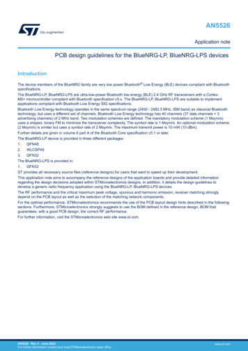
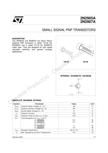
BlueNRG-LPFigure 1. The BlueNRG-LP block diagram256 kB FlashJTAG/SWDNVICSRAM0Cortex-M0 SRAM1SRAM2DMA (8 ch)MR BLEAHB LiteDMAMUXSRAM3PKA RAMRNGPWRCRCCLSE32 kHzGPIO0LSI32 kHzGPIO1CRCSYSCFGADCAPBHSE32 MHzRC64MPLLRTCIWDGTIM1Power supply/POR/PDR/PVDDS13282 - Rev 5SPI1SPI2/I2S2SPI3/I2S3I2C1I2C2USARTLPUARTpage 4/73
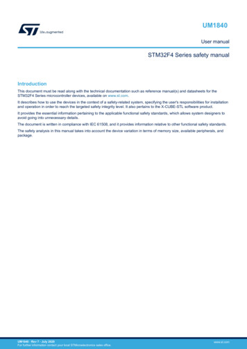
BlueNRG-LPFunctional overview1Functional overview1.1System architectureThe main system consists of 32-bit multilayer AHB bus matrix that interconnects: Three masters: – CPU (Cortex -M0 ) core S-bus– DMA1– Radio systemNine slaves:–––––––––Internal Flash memory on CPU (Cortex -M0 ) S busInternal SRAM0 (16 kB)Internal SRAM1 (16 kB)Internal SRAM2 (16 kB)Internal SRAM3 (16 kB)APB0 peripherals (through an AHB to APB bridge)APB1 peripherals (through an AHB to APB bridge)AHB0 peripheralsAHBRF including AHB to APB bridge and radio peripherals (connected to APB2)The bus matrix provides access from a master to a slave, enabling concurrent access and efficient operation evenwhen several high-speed peripherals work simultaneously.Figure 2. Bus matrixDS13282 - Rev 5page 5/73
BlueNRG-LPARM Cortex–M0 core with MPU1.2ARM Cortex–M0 core with MPUThe BlueNRG-LP contains an ARM Cortex-M0 microcontroller core. The Cortex-M0 was developed to providea low-cost platform that meets the needs of CPU implementation, with a reduced pin count and low-powerconsumption, while delivering outstanding computational performance and an advanced response to interrupts.The Cortex-M0 can run from 1 MHz up to 64 MHz.The Cortex-M0 processor is built on a highly area and power optimized 32-bit processor core, with a 2-stagepipeline Von Neumann architecture. The processor delivers exceptional energy efficiency through a small butpowerful instruction set and extensively optimized design, providing high-end processing hardware including asingle-cycle multiplier.The interrupts are handled by the Cortex-M0 Nested Vector Interrupt Controller (NVIC). The NVIC controlsspecific Cortex-M0 interrupts as well as the BlueNRG-LP peripheral interrupts. With its embedded ARM core, theBlueNRG-LP family is compatible with all ARM tools and software.1.3Memories1.3.1Embedded Flash memoryThe Flash controller implements the erase and program Flash memory operation. The flash controller alsoimplements the read and write protection.The Flash memory features are: Memory organization: – 1 bank of 256 kB– Page size: 2 kB– Page number 12832-bit wide data read/writePage erase and mass eraseThe Flash controller features are: 1.3.2Flash memory read operationsFlash memory write operations: single data write or 4x32-bits burst writeFlash memory erase operationsPage write protect mechanismEmbedded SRAMThe BlueNRG-LP has a total of 64 kB of embedded SRAM, split into four banks as shown in the following table:Table 1. SRAM overview1.3.3SRAM bankSizeAddressRetained in DEEPSTOPSRAM016 kB0x2000 0000AlwaysSRAM116 kB0x2000 4000Programmable by the userSRAM216 kB0x2000 8000Programmable by the userSRAM316 kB0x2000 C000Programmable by the userEmbedded ROMThe BlueNRG-LP has a total of 7 kB of embedded ROM. This area is ST reserved and contains: 1.3.4The UART bootloader from which the CPU boots after each reset (first 6 kB of ROM memory)Some ST reserved values including the ADC trimming values (the last 1 kB of ROM memory)Embedded OTPThe one-time-programmable (OTP) is a memory of 1 kB dedicated for user data. The OTP data cannot beerased.DS13282 - Rev 5page 6/73
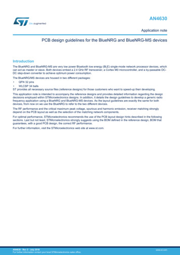
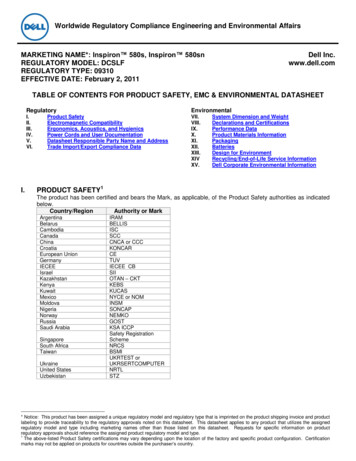
BlueNRG-LPSecurity and safetyThe user can protect the OTP data area by writing the last word at address 0x1000 1BFC and by performing asystem reset. This operation freezes the OTP memory from further unwanted write operations.1.3.5Memory protection unit (MPU)The MPU is used to manage accesses to memory to prevent one task from accidentally corrupting the memoryor resources used by any other active task. This memory area is organized into up to 8 protected areas. Theprotection area sizes are between 32 bytes and the whole 4 gigabytes of addressable memory.The MPU is especially helpful for applications where some critical or certified code has to be protected againstthe misbehavior of other tasks. It is usually managed by an RTOS (real-time operating system). If a programaccesses a memory location that is prohibited by the MPU, the RTOS can detect it and take action. In an RTOSenvironment, the kernel can dynamically update the MPU area settings, based on the process to be executed.The MPU is optional and can be bypassed for applications that do not need it.1.4Security and safetyThe BlueNRG-LP contains many security blocks for the BLE and the host application.It includes: Flash read/write protectionsAs protection against potential hacker attacks, the SWD access can be disabledSecure bootloader (refer to the dedicated BlueNRG-LP UART bootloader protocol application note AN5471)Customer storage of the BLE keysTrue random number generator (RNG)Private key accelerator (PKA) including:– Elliptic curve Diffie-Hellman (ECDH) public-private key pair calculation accelerator– Based on the Montgomery method for fast modular multiplications– Built-in Montgomery domain inward and outward transformations 1.5 AMBA AHB lite slave interface with a reduced command setCyclic redundancy check calculation unit (CRC)RF subsystemThe BlueNRG-LP embeds an ultra-low power radio, compliant with Bluetooth Low Energy (BLE) specification.The BLE features 1 Mbps and 2 Mbps transfer rates as well as long range options (125 kbps, 500 kbps), supportsmultiple roles simultaneously acting at the same time as Bluetooth Low Energy sensor and hub device.The BLE protocol stack is implemented by an efficient system partitioned as follows: 1.5.1Hardware part: BlueCore handling time critical and time consuming BLE protocol partsFirmware part: Arm Cortex -M0 core handling non time critical BLE protocol partsRF front-end block diagramThe RF front-end is based on a direct modulation of the carrier in TX, and uses a low IF architecture in RX mode.Thanks to an internal transformer with RF pins, the circuit directly interfaces the antenna (single endedconnection, impedance close to 50 Ω). The natural band pass behavior of the internal transformer simplifiesoutside circuitry aimed at harmonic filtering and out of band interferer rejection.In transmit mode, the maximum output power is user selectable through the programmable LDO voltage of thepower amplifier. A linearized, smoothed analog control offers a clean power ramp-up.In receive mode, the automatic gain control (AGC) can reduce the chain gain at both RF and IF locations, foroptimized interferer rejections. Thanks to the use of complex filtering and highly accurate I/Q architecture, highsensitivity and excellent linearity can be achieved.DS13282 - Rev 5page 7/73
BlueNRG-LPRF subsystemFigure 3. BlueNRG-LP RF block diagramTimer and PowercontrolAGCcontrolAGCTX SEQUENCERF controlADCRX AdjustPA rampgeneratorAdjustHSESMPSVDDSD VSSSD VLXSDLDOLDOLDOVFBSDMax PAlevelTrimmedbiasVDDRFNotes: QFN42 and QFN48: VSS through exposed pad, and VSSRF pins must be connected to ground plane.CSP49: VSSRF pins must be connected to ground plane.DS13282 - Rev 5page 8/73
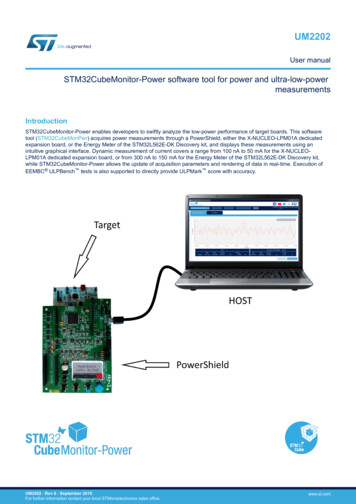
BlueNRG-LPPower supply management1.61.6.1Power supply managementSMPS step-down regulatorThe device integrates a step-down converter to improve low power performance when the VDD voltage is highenough. The SMPS output voltage can be programmed from 1.2 V to 1.90 V. It is internally clocked at 4 MHz or 8MHz.The device can be operated without the SMPS by just wiring its output to VDD. This is the case for applicationswhere the voltage is low, or where the power consumption is not critical.Except for the configuration SMPS OFF, an L/C BOM must be present on the board and connected to the VFBSDpad.Figure 4. Power supply configurationDS13282 - Rev 5page 9/73
BlueNRG-LPPower supply management1.6.2Power supply schemesThe BlueNRG-LP embeds three power domains: VDD33 (VDDIO or VDD): – the voltage range is between 1.7 V and 3.6 V– it supplies a part of the I/O ring, the embedded regulators and the system analog IPs as powermanagement block and embedded oscillatorsVDD12o: – always-on digital power domain– this domain is generally supplied at 1.2 V during active phase of the device– this domain is supplied at 1.0 V during low power mode (DEEPSTOP)VDD12i:– interruptible digital power domain– this domain is generally supplied at 1.2 V during active phase of the device– this domain is shut down during low power mode (DEEPSTOP)Figure 5. Power supply domain overviewVDDIOVFBSDSMPSVREG PADVGATENCMDNOCMDNIVGATEPMLDOLP-RegV33 Domain(VDDIO)HSE, LSI, LSEPDR, POR, IBLE wakeup,RTC, WDOG,PWRCo,RCCoVDD12IRFLDOsVRFInterruptible domain(VDD12I)CPURF FSMBLEPeripheralsRCCiAnalogRFLinear voltage regulatorsThe digital power supplies are provided by different regulators: The main LDO (MLDO): – it provides 1.2 V from a 1.4-3.3 V input voltage– it supplies both VDD12i and VDD12o when the device is active– it is disabled during the low power mode (DEEPSTOP)Low power LDO (LPREG): – it stays enabled during both active and low power phases– it provides 1.0 V voltage– it is not connected to the digital domain when the device is active– it is connected to the VDD12o domain during low power mode (DEEPSTOP)A dedicated LDO (RFLDO) to provide a 1.2 V to the analog RF blockAn embedded SMPS step-down converter is available (inserted between the external power and the LDOs).DS13282 - Rev 5page 10/73
BlueNRG-LPOperating modes1.6.4Power supply supervisorThe BlueNRG-LP device embeds several power voltage monitoring: 1.7Power-on-reset (POR): during the power-on, the device remains in reset mode if VDDIO is below a VPORthreshold (typically 1.65 V)Power-down-reset (PDR): during power-down, the PDR puts the device under reset when the supply voltage(VDD) drops below the VPDR threshold (around 20 mV below VPOR). The PDR feature is always enabledPower voltage detector (PVD): can be used to monitor the VDDIO (against a programmed threshold) oran external analog input signal. When the feature is enabled and the PVD measures a voltage below thecomparator, an interrupt is generated (if unmasked)Operating modesSeveral operating modes are defined for the BlueNRG-LP: RUN modeDEEPSTOP modeSHUTDOWN modeTable 2. Relationship between the low power modes and functional ONFlashOFFOFFONONRAMOFFON/OFF granularity 16 kBON/OFFON/OFFRadioOFFOFFON/OFFON/OFFSupply systemOFFOFFON ( DC-DC ON/OFF)ON ( DC-DC ON/OFF)Register retentionOFFONONONHS clockOFFOFFONONLS e-on RTCOFFON/OFFON/OFFNAWake-on GPIOsOFFON/OFFON/OFFNAWake-on reset pinONONONNARUN modeIn RUN mode the BlueNRG-LP is fully operational: All interfaces are activeThe internal power supplies are activeThe system clock and the bus clock are runningThe CPU core and the radio can be usedThe power consumption may be reduced by gating the clock of the unused peripherals.1.7.2DEEPSTOP modeThe DEEPSTOP is the only low power mode of the BlueNRG-LP allowing the restart from a saved contextenvironment and the application at wake-up to go on running.The conditions to enter the DEEPSTOP mode are: The radio is sleeping (no radio activity)The CPU is sleeping (WFI with SLEEPDEEP bit activated)No unmasked wake-up sources are activeThe low power mode selection (LPMS) bit of the power controller unit is 0 (default)In DEEPSTOP mode:DS13282 - Rev 5page 11/73
BlueNRG-LPOperating modes The system and the bus clocks are stoppedOnly the essential digital power domain is ON and supplied at 1.0 VThe bank RAM0 is kept in retentionThe other banks of RAM can be in retention or not, depending on the software configurationThe low speed clock can be running or stopped, depending on the software configuration:– ON or OFF– Sourced by LSE or by LSIThe RTC and the IWDG stay active, if enabled and the low speed clock is ONThe I/Os pull-up and pull-down can be controlled during DEEPSTOP mode, depending on the softwareconfigurationThe radio wake-up block, including its timer, stay active (if enabled and the low speed clock is ON)Eight I/Os (PA4/ PA5/ PA6/ PA7/ PA8/ PA9/ PA10/ PA11) can be in output driving:– A static low or high level– The low speed clock– The RTC outputPossible wake-up sources are: The radio block is able to generate two events to wake up the system through its embedded wake-up timerrunning on low speed clock:– Radio wake-up time is reached– CPU host wake-up time is reachedThe RTC can generate a wake-up eventThe IWDG can generate a reset eventUp to 28 GPIOs are able to wake up the system (PA0 to PA15 and PB0 to PB11)At the wake-up, all the hardware resources located in the digital power domain that are OFF during theDEEPSTOP mode, are reset. The CPU reboots. The wake-up reason is visible in the register of the powercontroller.1.7.3SHUTDOWN modeThe SHUTDOWN mode is the least power consuming mode.The conditions to enter SHUTDOWN mode are the same conditions needed to enter DEEPSTOP mode exceptthat the LPMS bit of the power controller unit is 1.In SHUTDOWN mode, the BlueNRG-LP is in ultra-low power consumption: all voltage regulators, clocks and theRF interface are not powered. The BlueNRG-LP can enter shutdown mode by internal software sequence. Theonly way to exit shutdown mode is by asserting and deasserting the RSTN pin.In SHUTDOWN mode: The system is powered down as both the regulators are OFFThe VDDIO power domain is ONAll the clocks are OFF, LSI and LSE are OFFThe I/Os pull-up and pull-down can be controlled during SHUTDOWN mode, depending on the softwareconfigurationThe only wake-up source is a low pulse on the RSTN pinThe exit from SHUTDOWN is similar to a POR startup. The PDR feature can be enabled or disabled duringSHUTDOWN.DS13282 - Rev 5page 12/73
BlueNRG-LPReset management1.8Reset managementThe BlueNRG-LP offers two different resets: The PORESETn: this reset is provided by the low power management unit (LPMU) analog block andcorresponds to a POR or PDR root cause. It is linked to power voltage ramp-up or ramp-down. This resetimpacts all resources of the BlueNRG-LP. The exit from SHUTDOWN mode is equivalent to a POR and thusgenerates a PORESETn. The PORESETn signal is active when the power supply of the device is below athreshold value or when the regulator does not provide the target voltage.The PADRESETn (system reset): this reset is built through several sources:– PORESETn– Reset due to the watchdogThe BlueNRG-LP device embeds a watchdog timer, which may be used to recover from software crashes– Reset due to CPU LockupThe Cortex-M0 generates a lockup to indicate the core is in the lock-up state resulting from anunrecoverable exception. The lock-up reset is masked if a debugger is connected to the Cortex-M0 – Software system resetThe system reset request is generated by the debug circuitry of the Cortex -M0 . The debugger setsthe SYSRESETREQ bit of the application interrupt and reset control register (AIRCR). This system resetrequest through the AIRCR can also be done by the embedded software (into the hardfault handler forinstance)– Reset from the RSTN external pinThe RSTN pin toggles to inform that a reset has occurred This PADRESETn resets all resources of the BlueNRG-LP, except:Debug featuresFlash controller key managementRTC timerPower controller unitPart of the RCC registersThe pulse generator guarantees a minimum reset pulse duration of 20 μs for each internal reset source. In caseof reset from the RSTN external pad, the reset pulse is generated when the pad is asserted low.1.9Clock managementThree different clock sources may be used to drive the system clock of the BlueNRG-LP: HSI: high speed internal 64 MHz RC oscillatorPLL64M: 64 MHz PLL clockHSE: high speed 32 MHz external crystalThe BlueNRG-LP has also a low speed clock tree used by some timers in the radio, RTC and IWDG.Four different clock sources can be used for this low speed clock tree: Low speed internal (LSI): low speed and low drift internal RC with a fixed frequency between 24 kHz and 49kHz depending on the sampleLow speed external (LSE) from:– An external crystal 32.768 kHz– A single-ended 32.738 kHz input signalA 32 kHz clock (CLK 16 MHz/512 in Figure 6. Clock tree) obtained by dividing HSI or HSE. In this case, theslow clock is not available in DEEPSTOP low power modeLSI LPMU: 32 kHz clock used by the low power management unit (LPMU) analog block.By default, after a system reset, all low speed sources are OFF.Both the activation and the selection of the slow clock are relevant during the DEEPSTOP mode and at wakeupas slow clock generates a clock for the timers involved in wake-up event generation.The HSI and the PLL64M clocks are provided by the same analog block called RC64MPLL. The 64 MHz clockoutput by this block can be: DS13282 - Rev 5A non-accurate clock when no external XO provides an input clock to this block (HSI)An accurate clock when the external XO provides the 32 MHz and once its internal PLL is locked (PLL64M)page 13/73
BlueNRG-LPClock managementThis fast clock source is used to generate all the fast clock of the device through dividers. After reset, theCLK SYS is divided by four to provide a 16 MHz to the whole system (CPU, DMA, memories and peripherals).This fast clock source is also used to generate several internal fast clocks in the system: Always 32 MHz requested by a few peripherals like the radioAlways 16 MHz requested by a few peripherals like serial interfaces (to maintain fixed the baud rate whilesystem clock is switching from one frequency to another) or like the Flash controller and radio (to have a fixedreference clock to manage delays)Figure 6. Clock treeLSI RCO32kHzLSI LPMURCO 32kHzCLKSLOWSELLCOSELLCOCK RTC,CK WDG,CK BLEWKUPCLK 16MHz/512OSC32k OUTCLK TIM1LSE OSC32kHzSYSCLKDIVOSC32k INSYSCLK PREOSC OUTOSC INCLK SYS/1, /2, . , /32HSE OSC32MHz1100SYSCLK PRE/1, /2, . , /64to CPU,AHB0,APB0,APB1,SRAM,PKA,CLK SPI1HSESELHSIRCO PLL64MHzHSESELSYSCLKDIV/41/20CLKANA ADCCLK SMPSCLK SMPSSMPSDIVCLK SYSMCO/1, /2, . , /16/21/40HSEHSICLK 16MHz1HSESELCLK 16MHz/512CLKANA ADC,CLK USART,CLK I2C,CLK BLE16,CLK FLASH,CLK PWR,CLK RNGCLK LPUARTCLKSYS BLE0MCOSEL1/2BLECLKDIVCLK 32MHzCLK BLE32,CLKDIG ADC0HSESEL1CLK SPI2/I2S2CLK 16MHz0SP2CKSEL1CLK SPI3/I2S30SP3CKSELIt is possible to output some internal clocks on external pads: the low speed clocks can be output on the LCO I/Othe high speed clocks can be output on the MCO I/OThis is possible by programming the associated I/O in the correct alternate function.Most of the peripherals only use the system clock except:DS13282 - Rev 5page 14/73
BlueNRG-LPBoot mode 1.10I2C, USART, LPUART: they always use a16 MHz clock to have a fixed reference clock for baud ratemanagement. The goal is to allow the CPU to boost or slow down the system clock (depending on on-goingactivities) without impacting a potential on-going serial interface transfer on external I/OsSPI: when the I2S mode is used, the baud rate is always managed through the 16 MHz or 32 MHz clock.When modes other than the I2S run, the baud rate is managed by the system clock. This implies its baud rateis impacted by dynamic system clock frequency changesRNG: in parallel to the system clock, the RNG always uses 16 MHz clock to generate at a constant frequencythe random number whatever the system clock frequencyFlash controller: in parallel to the system clock, the Flash controller always uses 16 MHz clock to generatespecific delays required by the Flash memory during programming and erase operations for examplePKA: in parallel to the system clock, the PKA uses a clock at half of the system clock frequencyRadio: it does not directly use the system clock for its APB/AHB interfaces, but the system clock with apotential divider (1 or 2 or 4). In parallel, the radio always uses 16 MHz and always 32 MHz for modulator,demodulator and to have a fixed reference clock to manage specific delaysADC: in parallel to the system clock, ADC uses a 64 MHz prescaled clock running at 16 MHzBoot modeFollowing CPU boot, the application software can modify the memory map at address 0x0000 0000. Thismodification is performed by programming the REMAP bit in the Flash controller.The following memory can be remapped: 1.11Main Flash memorySRAM0 memoryEmbedded UART bootloaderThe BlueNRG-LP has a pre-programmed bootloader supporting UART protocol with automatic baud ratedetection. The main features of the embedded bootloader are: Auto baud rate detection up to 1 MbpsFlash mass erase, section eraseFlash programmingFlash readout protection enable/disableThe pre-programmed bootloader is an application, which is stored in the BlueNRG-LP internal ROM atmanufacturing time by STMicroelectronics. This application allows upgrading the device Flash with a userapplication using a serial communication channel (UART).Bootloader is activated by hardware by forcing PA10 high during hardware reset, otherwise, application residing inFlash is launched.Note:Bootloader protocol is described in a separate application note (the BlueNRG-LP UART bootloader protocol,AN5471)1.12General purpose inputs/outputs (GPIO)Each of the GPIO pins can be configured by software as output (push-pull or open-drain), as input (with or withoutpull-up or pull-down) or as peripheral alternate function. Most of the GPIO pins are shared with digital or analogalternate functions. Fast I/O toggling can be achieved thanks to their mapping on the AHB0 bus.The I/Os alternate function configuration can be locked if needed following a specific sequence in order to avoidspurious writing to the I/Os registers.1.13Direct memory access (DMA)The DMA is used in order to provide high-speed data transfer between peripherals and memory as well asmemory-to-memory. Data can be quickly moved by DMA without any CPU actions. In this manner, CPU resourcesare free for other operations.The DMA controller has eight channels in total. Each has an arbiter to handle the priority among DMA requests.DMA main features are: DS13282 - Rev 5Eight independently configurable channels (requests)page 15/73
BlueNRG-LPNested vectored interrupt controller (NVIC) 1.14Each of the eight channels is connected to dedicated hardware DMA requests, software trigger is alsosupported on each channel. This configuration is done by softwarePriorities among requests from channels of DMA are software programmable (four levels consisting of veryhigh, high, medium, low) or hardware in case of equality (request 1 has priority over request 2, and so on)Independent source and destination transfer size (byte, half word, word), emulating packing and unpacking.Source/destination addresses must be aligned on the data sizeSupport for circular buffer managementThree event flags (DMA half transfer, DMA transfer complete and DMA transfer error) logically ORed togetherin a single interrupt request for each channelMemory-to-memory transfer (RAM only)Peripheral-to-memory and memory-to-peripheral, and peripheral-to-peripheral transfersAccess to SRAMs and APB1 peripherals as source and destinationProgrammable number of data to be transferred: up to 65536Nested vectored interrupt controller (NVIC)The interrupts are handled by the Cortex -M0 nested vector interrupt controller (NVIC). NVIC controls specificC
Mobile phone peripherals PC peripherals. Description. The BlueNRG-LP is an ultra-low power programmable Bluetooth Low Energy wireless SoC solution. It embeds STMicroelectronics's state-of-art 2.4 GHz RF radio IPs combining unparalleled performance with extremely long-battery lifetime.