Transcription
UM1840User manualSTM32F4 Series safety manualIntroductionThis document must be read along with the technical documentation such as reference manual(s) and datasheets for theSTM32F4 Series microcontroller devices, available on www.st.com.It describes how to use the devices in the context of a safety-related system, specifying the user's responsibilities for installationand operation in order to reach the targeted safety integrity level. It also pertains to the X-CUBE-STL software product.It provides the essential information pertaining to the applicable functional safety standards, which allows system designers toavoid going into unnecessary details.The document is written in compliance with IEC 61508, and it provides information relative to other functional safety standards.The safety analysis in this manual takes into account the device variation in terms of memory size, available peripherals, andpackage.UM1840 - Rev 7 - July 2020For further information contact your local STMicroelectronics sales office.www.st.com
UM1840About this document1About this document1.1Purpose and scopeThis document describes how to use Arm Cortex ‑M4 -based STM32F4 Series microcontroller unit (MCU)devices (further also referred to as Device(s)) in the context of a safety‑related system, specifying the user'sresponsibilities for installation and operation, in order to reach the desired safety integrity level.It is useful to system designers willing to evaluate the safety of their solution embedding one or more Device(s).For terms used, refer to the glossary at the end of the document.Note:Arm is a registered trademark of Arm Limited (or its subsidiaries) in the US and/or elsewhere.1.2Normative referencesThis document is written in compliance with the IEC 61508 international norm for functional safety of electrical,electronic and programmable electronic safety-related systems, version IEC 61508:1-7 IEC:2010.The other functional safety standards considered in this manual are: ISO 13849-1:2015, ISO13849-2:2012 IEC 62061:2005 AMD1:2012 AMD2:2015 IEC 61800-5-2:2016The following table maps the document content with respect to the IEC 61508-2 Annex D requirements.Table 1. Document sections versus IEC 61508-2 Annex D safety requirementsSafety requirementD2.1 a) a functional specification of the functions capable of being performedSection number3D2.1 b) identification of the hardware and/or software configuration of the Compliant item3.2D2.1 c) constraints on the use of Compliant item or assumptions on which analysis of the behavior orfailure rates of the item are based3.2D2.2 a) the failure modes of Compliant item due to random hardware failures, that result in a failure ofthe function and that are not detected by diagnostics internal to Compliant item;D2.2 b) for every failure mode in a), an estimated failure rate;D2.2 c) the failure modes of Compliant item due to random hardware failures, that result in a failure ofthe function and that are detected by diagnostics internal to Compliant item;3.7D2.2 d) the failure modes of the diagnostics, internal to Compliant item due to random hardware failures,that result in a failure of the diagnostics to detect failures of the function;D2.2 e) for every failure mode in c) and d), the estimated failure rate;D2.2 f) for every failure mode in c) that is detected by diagnostics internal to Compliant item, thediagnostic test interval;D2.2 g) for every failure mode in c) the outputs of Compliant item initiated by the internal diagnostics;3.2.23.6D2.2 h) any periodic proof test and/or maintenance requirements;D2.2 i) for those failure modes, in respect of a specified function, that are capable of being detected byexternal diagnostics, sufficient information must be provided to facilitate the development of an externaldiagnostics capability.3.7D2.2 j) the hardware fault tolerance;D2.2 k) the classification as type A or type B of that part of Compliant item that provides the function (see7.4.4.1.2 and 7.4.4.1.3);UM1840 - Rev 73page 2/96
UM1840Reference documents1.3UM1840 - Rev 7Reference documents[1]AN5141: Results of FMEA on STM32F4 Series microcontrollers.[2]AN5140: FMEDA snapshots for STM32F4 Series microcontrollers.page 3/96
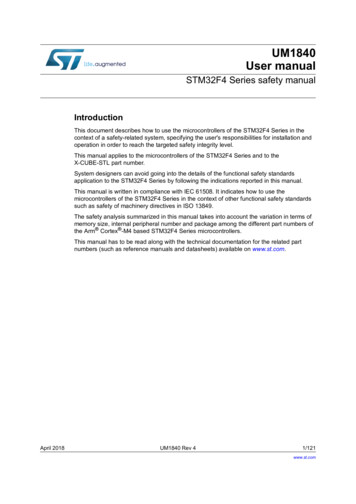
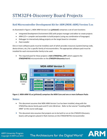
UM1840Device development process2Device development processSTM32 series product development process (see Figure 1), compliant with the IATF 16949 standard, is a set ofinterrelated activities dedicated to transform customer specification and market or industry domain requirementsinto a semiconductor device and all its associated elements (package, module, sub-system, hardware, software,and documentation), qualified with ST internal procedures and fitting ST internal or subcontracted manufacturingtechnologies.Figure 1. STMicroelectronics product development process1 Conception·········UM1840 - Rev 7Key characteristics andrequirements related to futureuses of the deviceIndustry domain(s), specificcustomer requirements anddefinition of controls and testsneeded for complianceProduct target specificationand strategyProject managerappointment to drive productdevelopmentEvaluation of thetechnologies, design toolsand IPs to be usedDesign objectivespecification and productvalidation strategyDesign for qualitytechniques (DFD, DFT, DFR,DFM, ) definitionArchitecture and positioningto make sure the softwareand hardware systemsolutions meet the targetspecificationProduct approval strategyand project plan2 Design &validation· Semiconductor designdevelopment· Hardware development· Software development· Analysis of new productspecification to forecastreliability performance· Reliability plan, reliabilitydesign rules, prediction offailure rates for operating lifetest using Arrhenius’s law andother applicable models· Use of tools andmethodologies such asAPQP, DFM, DFT, DFMEA· Detection of potentialreliability issues and solutionto overcome them· Assessment of EngineeringSamples (ES) to identify themain potential failuremechanisms· Statistical analysis ofelectrical parameter drifts forearly warning in case of fastparametric degradation (suchas retention tests)· Failure analysis on failedparts to clarify failure modesand mechanisms and identifythe root causes· Physical destructiveanalysis on good parts afterreliability tests when required· Electrostatic discharge(ESD) and latch-up sensitivitymeasurement3 Qualification· Successful completion ofthe product qualificationplan· Secure product deliverieson advanced technologiesusing stress methodologiesto detect potential weakparts· Successful completion ofelectrical characterization· Global evaluation of newproduct performance toguarantee reliability ofcustomer manufacturingprocess and final applicationof use (mission profile)· Final disposition forproduct test, control andmonitoringpage 4/96
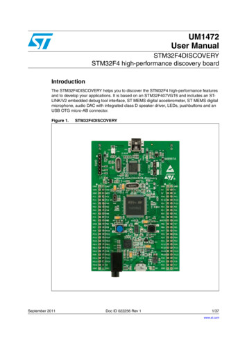
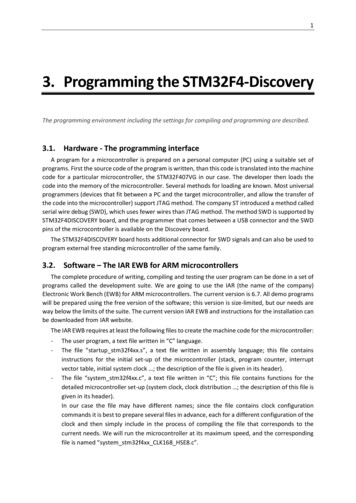
UM1840Reference safety architecture3Reference safety architectureThis section reports details of the STM32F4 Series safety architecture.3.1Safety architecture introductionDevice(s) analyzed in this document can be used as Compliant item(s) within different safety applications.The aim of this section is to identify such Compliant item(s), that is, to define the context of the analysis withrespect to a reference concept definition. The concept definition contains reference safety requirements, includingdesign aspects external to the defined Compliant item.As a consequence of Compliant item approach, the goal is to list the system-related information consideredduring the analysis, rather than to provide an exhaustive hazard and risk analysis of the system around Device.Such information includes, among others, application-related assumptions for danger factors, frequency offailures and diagnostic coverage already guaranteed by the application.3.2Compliant itemThis section defines the Compliant item term and provides information on its usage in different safety architectureschemes.3.2.1Definition of Compliant itemAccording to IEC 61508:1 clause 8.2.12, Compliant item is any item (for example an element) on which a claim isbeing made with respect to the clauses of IEC 61508 series. Any mature Compliant item must be described in asafety manual available to End user.In this document, Compliant item is defined as a system including one or two STM32 devices (see Figure 2). Thecommunication bus is directly or indirectly connected to sensors and actuators.Figure 2. STM32 as Compliant erProcessing elementSTM32device(s)Compliant itemRemotecontrollerARemotecontrollerAOther components might be related to Compliant item, like the external HW components needed to guaranteeeither the functionality of Device (external memory, clock quartz and so on) or its safety (for example, the externalwatchdog or voltage supervisors).A defined Compliant item can be classified as element according to IEC61508-4, 3.4.5.3.2.2Safety functions performed by Compliant itemIn essence, Compliant item architecture encompasses the following processes performing the safety function or apart of it: input processing elements (PEi) reading safety related data from the remote controller connected to thesensor(s) and transferring them to the following computation elements computation processing elements (PEc) performing the algorithm required by the safety function andtransferring the results to the following output elements output processing elements (PEo) transferring safety related data to the remote controller connected to theactuatorUM1840 - Rev 7page 5/96
UM1840Compliant item in 1oo2 architecture, potentially a further voting processing element (PEv)the computation processing elements can be involved (to the extent depending to the target safety integrity)in the implementation of local software-based diagnostic functions; this is represented by the block PEdprocesses external to Compliant item ensuring safety integrity, such as watchdog (WDTe) and voltagemonitors (VMONe)The role of the PEv process is clarified in Section 3.2.4 Reference safety architectures - 1oo2. The role of theWDTe and VMONe external processes is clarified under Section 3.6 Hardware and software diagnostics: WDTe: refer to External watchdog – CPU SM 5 and Control flow monitoring in Application software –CPU SM 1, VMONe: refer to Supply voltage internal monitoring (PVD) – VSUP SM 1 and System-level power supplymanagement - VSUP SM 5.In summary, Devices support the implementation of End user safety functions consisting of three operations: safe acquisition of safety-related data from input peripheral(s) safe execution of Application software program and safe computation of related data safe transfer of results or decisions to output peripheral(s)Claims on Compliant item and computation of safety metrics are done with respect to these three basicoperations.According to the definition for implemented safety functions, Compliant item (element) can be regarded as type B(as per IEC61508-2, 7.4.4.1.3 definition). Despite accurate, exhaustive and detailed failure analysis, Device hasto be considered as intrinsically complex. This implies its type B classification.Two main safety architectures are identified: 1oo1 (using one Device) and 1oo2 (using two Devices).3.2.3Reference safety architectures - 1oo11oo1 reference architecture (Figure 3) ensures safety integrity of Compliant item through combining Deviceinternal processes (implemented safety mechanisms) with external processes WDTe and VMONe.1oo1 reference architecture targets safety integrity level (SIL) SIL2.Figure 3. 1oo1 reference M1840 - Rev 7page 6/96
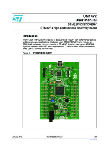
UM1840Compliant item3.2.4Reference safety architectures - 1oo21oo2 reference architecture (Figure 4) contains two separate channels, either implemented as 1oo1 referencearchitecture ensuring safety integrity of Compliant item through combining Device internal processes(implemented safety mechanisms) with external processes WDTe and VMONe. The overall safety integrity is thenensured by the external voter PEv, which allows claiming hardware fault tolerance (HFT) equal to 1. Achievementof higher safety integrity levels as per IEC61508-2 Table 3 is therefore possible. Appropriate separation betweenthe two channels (including power supply separation) should be implemented in order to avoid huge impact ofcommon-cause failures (refer to Section 4.2 Analysis of dependent failures). However, β and βD parameterscomputation is required.1oo2 reference architecture targets SIL3.Figure 4. 1oo2 reference atorsPEoPEcPEdVMONeUM1840 - Rev 7WDTepage 7/96
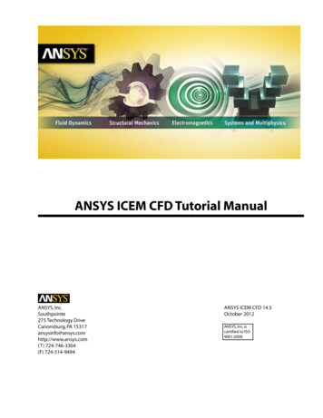
UM1840Safety analysis assumptions3.3Safety analysis assumptionsThis section collects all assumptions made during the safety analysis of Devices.3.3.1Safety requirement assumptionsThe safety concept specification, the overall safety requirement specification and the consequent allocationdetermine the requirements for Compliant item as further listed. ASR stands for assumed safety requirement.Caution:It is End user’s responsibility to check the compliance of the final application with these assumptions.ASR1: Compliant item can be used to implement four kinds of safety function modes of operation according topart 4,3.5.16: a continuous mode (CM) or high-demand (HD) SIL3 safety function (CM3), or a low-demand (LD) SIL3 safety function (LD3), or a CM or HD SIL2 safety function (CM2), or a LD SIL2 safety function (LD2).ASR2: Compliant item is used to implement safety function(s) allowing a specific worst-case time budget (seenote below) for the STM32 MCU to detect and react to a failure. That time corresponds to the portion of theprocess safety time (PST) allocated to Device (STM32xx Series duty in Figure 5) in error reaction chain at systemlevel.Note:The computation for time budget mainly depends on the execution speed for periodic tests implemented bysoftware. Such duration might depends on the actual amount of hardware resources (RAM memory, Flashmemory, peripherals) actually declared as safety-related. Further constraints and requirements fromIEC61508-2, 7.4.5.3 must be considered.Figure 5. Allocation and target for STM32 PSTSTM32xx Series dutyMCU detectionFW reactionEnd user dutySW reaction .Actuator reactionSystem-level PSTASR3: Compliant item is used to implement safety function(s) that can be continuously powered on for a periodover eight hours. It is assumed to not require any proof test, and the lifetime of the product is considered to be noless than 10 years.ASR4: It is assumed that only one safety function is performed or if many, all functions are classified with thesame SIL and therefore they are not distinguishable in terms of their safety requirements.ASR5: In case of multiple safety function implementations, it is assumed that End user is responsible to dulyensure their mutual independence.ASR6: It is assumed that there are no non-safety-related functions implemented in Application software,coexisting with safety functions.ASR7: It is assumed that the implemented safety function(s) does (do) not depend on transition of Device to andfrom a low-power state.ASR8: The local safe state of Compliant item is the one in which either: SS1: Application software is informed by the presence of a fault and a reaction by Application software itselfis possible. SS2: Application software cannot be informed by the presence of a fault or Application software is not ableto execute a reaction.Note:UM1840 - Rev 7End user must take into account that random hardware failures affecting Device can compromise its operation(for example failure modes affecting the program counter prevent the correct execution of software).page 8/96
UM1840Electrical specifications and environment limitsThe following table provides details on the SS1 and SS2 safe states.Table 2. SS1 and SS2 safe state detailsSafestateConditionCompliant itemactionSystem transition to safestate – 1oo1 architectureSystem transition to safestate – 1oo2 architectureFault reporting toApplicationsoftwareApplication software drivesthe overall system in its safestateApplication software in one ofthe two channels drives theoverall system in its safe stateSS1Application software is informedby the presence of a fault and areaction by Application softwareitself is possible.SS2Application software cannot beinformed by the presence of aReset signalfault or Application software is not issued by WDTeable to execute a reaction.WDTe drives the overallPEv drives the overall systemsystem in its safe state (“safein its safe state(1)shut-down”)1. Safe state achievement intended here is compliant to Note on IEC 61508-2, 7.4.8.1ASR9: It is assumed that the safe state defined at system level by End user is compatible with the assumed localsafe state (SS1, SS2) for Compliant item.ASR10: Compliant item is assumed to be analyzed according to routes 1H and 1S of IEC 61508-2.Note:Refer to Section 3.5 Systematic safety integrity and Section 3.6 Hardware and software diagnostics.ASR11: Compliant item is assumed to be regarded as type B, as per IEC 61508:2, 7.4.4.1.2.3.4Electrical specifications and environment limitsTo ensure safety integrity, the user must operate Device(s) within its (their) specified: absolute maximum rating capacity operating conditionsFor electrical specifications and environmental limits of Device(s), refer to its (their) technical documentation suchas datasheet(s) and reference manual(s) available on www.st.com.3.5Systematic safety integrityAccording to the requirements of IEC 61508 -2, 7.4.2.2, the Route 1S is considered in the safety analysis ofDevice(s). As clearly authorized by IEC61508-2, 7.4.6.1, STM32 MCU products can be considered as standard,mass-produced electronic integrated devices, for which stringent development procedures, rigorous testing andextensive experience of use minimize the likelihood of design faults. However, ST internally assesses thecompliance of the Device development flow, through techniques and measures suggested in the IEC 61508-2Annex F. A safety case database (see Section 5 List of evidences) keeps evidences of the current compliancelevel to the norm.3.6Hardware and software diagnosticsThis section lists all the safety mechanisms (hardware, software and application-level) considered in the Devicesafety analysis. It is expected that users are familiar with the architecture of Device, and that this document isused in conjunction with the related Device datasheet, user manual and reference information. To avoidinconsistency and redundancy, this document does not report device functional details. In the followingdescriptions, the words safety mechanism, method, and requirement are used as synonyms.As the document provides information relative to the superset of peripherals available on the devices it covers(not all devices have all peripherals), users are supposed to disregard any recommendations not applicable totheir Device part number of interest.Information provided for a function or peripheral applies to all instances of such function or peripheral on Device.Refer to its reference manual or/and datasheet for related information.UM1840 - Rev 7page 9/96
UM1840Hardware and software diagnosticsThe implementation guidelines reported in the following section are for reference only. The safety verificationexecuted by ST during the Device safety analysis and related diagnostic coverage figures reported in this manual(or related documents) are based on such guidelines. For clarity, safety mechanisms are grouped by Devicefunction.Information is organized in form of tables, one per safety mechanism, with the following fields:SM CODEUnique safety mechanism code/identifier used also in FMEA document. Identifiers use the schememmm SM x where mmm is a 3- or 4-letter module (function, peripheral) short name, and x is anumber. It is possible that the numbering is not sequential (although usually incremental) and/or thatthe module short name is different from that used in other documents.DescriptionShort mnemonic descriptionOwnershipST: method is available on silicon.End user: method must be implemented by End user through Application software modification,hardware solutions, or both.DetailedimplementationDetailed implementation sometimes including notes about the safety concept behind the introductionof the safety mechanism.Error reportingDescribes how the fault detection is reported to Application software.Fault detection timeTime that the safety mechanism needs to detect the hardware failure.Addressed faultmodelReports fault model(s) addressed by the diagnostic (permanent, transient, or both), and otherinformation: If ranked for Fault avoidance: method contributes to lower the probability of occurrence of afailure If ranked for Systematic: method is conceived to mitigate systematic errors (bugs) inApplication software designDependency onDevice configurationReports if safety mechanism implementation or characteristics change among different Device partnumbers.InitializationSpecific operation to be executed to activate the contribution of the safety mechanismPeriodicityContinuous : safety mechanism is active in continuous mode.Periodic: safety mechanism is executed periodically(1).On-demand: safety mechanism is activated in correspondence to a specified event (for instance,reception of a data message).Startup: safety mechanism is supposed to be executed only at power-up or during off-linemaintenance periods.Test for thediagnosticReports specific procedure (if any and recommended) to allow on-line tests of safety mechanismefficiency. If no specific procedure applies (as for the majority of safety mechanisms), the fieldindicates Not applicable.Multiple-faultprotectionReports the safety mechanism(s) associated in order to correctly manage a multiple-fault scenario(refer to Section 4.1.3 Notes on multiple-fault scenario).RecommendationsAdditional recommendations or limitations (if any) not reported in other fields.and known limitations1. In CM systems, safety mechanism can be accounted for diagnostic coverage contribution only if it is executed at least onceper PST. For LD and HD systems, constraints from IEC61508-2, 7.4.5.3 must be applied.3.6.1Arm Cortex -M4 CPUTable 3. CPU SM 0SM CODEUM1840 - Rev 7CPU SM 0DescriptionPeriodic core self-test software forOwnershipEnd user or STArm Cortex -M4CPU.page 10/96
UM1840Hardware and software diagnosticsSM CODEDetailed implementationCPU SM 0The software test is built around well-known techniques already addressed by IEC 61508:7,A.3.2 (Self-test by software: walking bit one-channel). To reach the required values ofcoverage, the self-test software is specified by means of a detailed analysis of all the CPUfailure modes and related failure modes distribution.Error reportingDepends on implementationFault detection timeDepends on implementationAddressed fault modelPermanentDependency on Device configurationNoneInitializationNonePeriodicityTest for the diagnosticMultiple-fault protectionRecommendations and known limitationsPeriodicSelf-diagnostic capabilities can be embedded in the software, according to the testimplementation design strategy chosen. The adoption of checksum protection on resultsvariables and defensive programming are recommended.CPU SM 5: External watchdogThis method is the main asset in STM32F4 Series safety concept. Hardware integrity of theCPU is a key factor, given that the defined diagnostics for MCU peripherals are to major partsoftware-based.Table 4. CPU SM 1SM CODECPU SM 1DescriptionControl flow monitoring in Application softwareOwnershipEnd userA significant part of the failure distribution of CPU core for permanent faults is related to failuremodes directly related to program counter loss of control or hang-up. Due to their intrinsicnature, such failure modes are not addressed by a standard software test method likeSM CPU 0. Therefore, it is necessary to implement a run-time control of Application softwareflow in order to monitor and detect deviation from the expected behavior due to such faults.Linking this mechanism to watchdog firing assures that severe loss of control (or, in the worstcase, a program counter hang-up) is detected.The guidelines for the implementation of the method are the following: Different internal states of Application software are well documented and described (theuse of a dynamic state transition graph is encouraged). Monitoring of the correctness of each transition between different states of Applicationsoftware is implemented. Transition through all expected states during the normal Application software programloop is checked. A function in charge of triggering the system watchdog is implemented in order toconstrain the triggering (preventing the issue of CPU reset by watchdog) also to thecorrect execution of the above-described method for program flow monitoring. The useof window feature available on internal window watchdog (WWDG) is recommended. The use of the independent watchdog (IWDG), or an external one, helps to implement amore robust control flow mechanism fed by a different clock source.Detailed implementationIn any case, safety metrics do not depend on the kind of watchdog in use (the adoption ofindependent or external watchdog contributes to the mitigation of dependent failures, seeSection 4.2.2 Clock).Error reportingFault detection timeAddressed fault modelDependency on Device configurationInitializationUM1840 - Rev 7Depends on implementationDepends on implementation. Higher value is fixed by watchdog timeout interval.Permanent/transientNoneDepends on implementationpage 11/96
UM1840Hardware and software diagnosticsSM CODEPeriodicityTest for the diagnosticMultiple-fault protectionRecommendations and known limitationsCPU SM 1ContinuousNot applicableCPU SM 0: Periodic core self-test softwareNoneTable 5. CPU SM 2SM CODEDescriptionOwnershipCPU SM 2Double computation in Application softwareEnd userA timing redundancy for safety-related computation is considered to detect transient faultsaffecting the Arm Cortex -M4 CPU subparts devoted to mathematical computations and dataaccess.The guidelines for the implementation of the method are the following:Detailed implementation The requirement needs be applied only to safety-relevant computation, which in case ofwrong result could interfere with the system safety functions. Such computation must betherefore carefully identified in the original Application software source code Both mathematical operation and comparison are intended as computation. The redundant computation for mathematical computation is implemented by usingcopies of the original data for second computation, and by using an equivalent formula ifpossibleError reportingDepends on implementationFault detection timeDepends on implementationAddressed fault modelDependency on Device configurationInitializationPeriodicityTest for the diagnosticMultiple-fault protectionRecommendations and known limitationsTransientNoneDepends on implementationContinuousNot applicableCPU SM 0: Periodic core self-test softwareEnd user is responsible to carefully avoid that the intervention of optimization features of theused compiler removes timing redundancies introduced according to this condition of use.Table 6. CPU SM 3SM CODEDescriptionOwnershipSTDetailed implementationError reportingFault detection timeAddressed fault modelDependency on Device configurationUM1840 - Rev 7CPU SM 3Arm Cortex -M4HardFault exceptionsHardFault exception raise is an intrinsic safety mechanism implemented in Arm Cortex -M4core, mainly dedicated to intercept systematic faults due to software limitations or error insoftware design (causing for example execution of undefined operations, unaligned addressaccess). This safety mechanism is also able to detect hardware random faults inside the CPUbringing to such described abnormal operations.High-priority interrupt eventDepends on implementation. Refer to functional documentation.Permanent/transientNonepage 12/96
UM1840Hardware and software diagnosticsSM CODEInitializationPeriodicityTest for the diagnosticMultiple-fault protectionRecommendations and known limitationsCPU SM 3NoneContinuousIt is possible to write a test procedure to verify the generation of the HardFault exception;anyway, given the expected minor contribution in terms of hardware random-failure detection,such implementation is optional.CPU SM 0: Periodic core self-test softwareEnabling related interrupt generation on the detection of errors is highly recommended.Table 7. CPU SM 4SM CODECPU SM 4DescriptionStack hardening for Application softwareOwnershipEnd userThe stack hardening method is required to address faults (mainly transient) affecting CPUregister bank. This method is based on source code modification, introducing informationredundancy in register-passed information to called functions.The guidelines for the implementation of the method are the following:Detailed implementation To pass also a redundant copy of the passed parameters values (possibly inverted) andto execute a coherence check in the function. To pass also a redundant copy of the passed pointers and to execute a coherencecheck in the function. For parameters that are not protected by redundancy, to implement defensiveprogramming techniques (plausibility check of passed values). For example enumeratedfields are to be checked for consistency.Error reportingDepends on implementationFault detection timeDepends on implementationAddressed fault modelDependency on Device configurationInitializationPeriodicityTest for the diagnosticMultiple-fault protectionRecommendations and known limitationsPermanent/transientNoneDepends on implementationOn demandNot applicableCPU SM 0: Periodic core self-test softwareThis method partially overlaps with defensive programming techniques required by IEC61508for software development. Therefore in presence of Application software qualified for safetyintegrity greater or equal to SC2, optimizations
This document must be read along with the technical documentation such as reference manual(s) and datasheets for the STM32F4 Series microcontroller devices, available on www.st.com. . STM32F4 Series safety manual UM1840 User manual UM1840 - Rev 7 - July 2020 For further information contact your local STMicroelectronics sales office.