Transcription
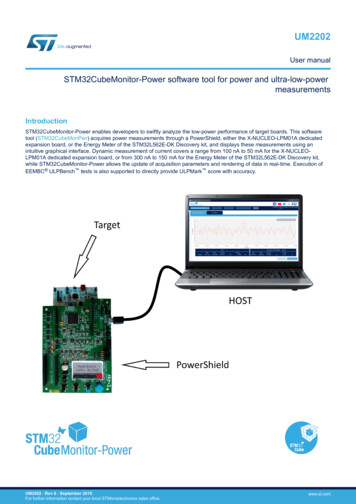
UM2202User manualSTM32CubeMonitor-Power software tool for power and nitor-Power enables developers to swiftly analyze the low-power performance of target boards. This softwaretool (STM32CubeMonPwr) acquires power measurements through a PowerShield, either the X-NUCLEO-LPM01A dedicatedexpansion board, or the Energy Meter of the STM32L562E-DK Discovery kit, and displays these measurements using anintuitive graphical interface. Dynamic measurement of current covers a range from 100 nA to 50 mA for the X-NUCLEOLPM01A dedicated expansion board, or from 300 nA to 150 mA for the Energy Meter of the STM32L562E-DK Discovery kit,while STM32CubeMonitor-Power allows the update of acquisition parameters and rendering of data in real-time. Execution ofEEMBC ULPBench tests is also supported to directly provide ULPMark score with accuracy.UM2202 - Rev 6 - September 2019For further information contact your local STMicroelectronics sales office.www.st.com
UM2202Features1Features Graphical power measurement tool on the target boardUsing a PowerShield:–Either the X-NUCLEO-LPM01A dedicated expansion board, shown in Figure 1–Or the Energy Meter of the STM32L562E-DK Discovery kit, shown in Figure 2.Performing ULPBench testsComputing ULPMark estimationSTM32CubeMonitor-Power supports STM32 32-bit microcontrollers based on the Arm Cortex -M processor.Note:Arm is a registered trademark of Arm Limited (or its subsidiaries) in the US and/or elsewhere.Figure 1. X-NUCLEO-LPM01A expansion boardFigure 2. STM32L562E-DK Discovery kitPictures are not contractual.UM2202 - Rev 6page 2/29
UM2202Getting started2Getting started2.1Computer requirementsSupported operating systems and architecturesNote: Windows 7, 8 and 10: 64-bit (x64) Linux (tested on Red Hat , Fedora , and Ubuntu , 64-bit) macOS (minimum version OS X Yosemite)Red Hat is a registered trademark of Red Hat, Inc.Fedora is a trademark of Red Hat, Inc.Ubuntu is a registered trademark of Canonical Ltd.macOS is a trademark of Apple Inc. registered in the U.S. and other countries.Software requirements Note:For Linux , Java runtime is required by the installer.Oracle and Java are registered trademarks of Oracle and/or its affiliates.Hardware requirements One free USB2 host portUSB Type-A to Micro-B cable200-Mbyte free storagePowerShield boardFirmware latest version (downloaded from the STM32-LPM01-XN webpage)STM32Lx-based target board (for which power measurements are performed)Note:For ULPBench tests, an ULPBench firmware must be running on the target board. This ULPBench firmware isdownloadable from EEMBC Internet site (www.eembc.org).2.2Installing2.2.1Installing STM32CubeMonitor-PowerDownload SetupSTM32CubeMonitor-Power.zip from www.st.com/stm32softwaretools, and unzip this file in atemporary location.Perform the setup process: For Windows, launch SetupSTM32CubeMonitor-Power-X.Y.Z.exe, which guides you through the setupprocess For Linux, launch SetupSTM32CubeMonitor-Power-X.Y.Z.jar, which guides you through the setup process For macOS, launch SetupSTM32CubeMonitor-Power-X.Y.Z.dmg and into the installer window, drag anddrop the STM32CubeMonitor-Power icon on the Applications iconNote:X.Y.Z represents STM32CubeMonitor-Power SW version.If another version of STM32CubeMonitor-Power is already installed, the existing version must be uninstalledbefore installing the new version (see Section 2.2.3 Uninstalling STM32CubeMonitor-Power to uninstall thecurrent version).2.2.2Installing the Virtual COM port driverNote:This section is only needed for Windows operating systems.Download the STM32 USB Virtual COM port driver (STSW-STM32102):UM2202 - Rev 6page 3/29
UM2202InstallingLaunch the executable in the zip file corresponding to the Windows version and the CPU architecture: 32-bit (x86)or 64-bit (x64).Plug then the PowerShield board with a USB cable, Windows must detect it as “STMicroelectronics Virtual COMport”, named COMxx (e.g. COM10).2.2.3Uninstalling STM32CubeMonitor-Power For Windows:–Open the Windows Control pane–Select Programs and Features to display the list of programs installed on your computer–Right-click on STM32CubeMonitor-Power from STMicroelectronics publisher and select the uninstallfunctionOr– Go in the STM32CubeMonitor-Power installation location (for example "C:\Program Files\STMicroelectronics\STM32CubeMonitor-Power"), go in "Uninstaller folder", and launch "uninstaller.jar"For Linux:–Go in the STM32CubeMonitor-Power installation location (for example " HOME/STMicroelectronics/STM32CubeMonitor-Power"), go in "Uninstaller folder" and launch "uninstaller.jar"For macOS:–Drag and drop the STM32CubeMonitor-Power application icon onto the Trash icon2.2.4Uninstalling the Virtual COM port driverNote:This section is only needed for Windows operating systems.To uninstall the STMicroelectronics USB Virtual COM port driver, follow the steps below: Open the Windows Control pane Select Programs and Features to display the list of programs installed on your computer Right-click on "Virtual Com port driver" from STMicroelectronics publisher and select the uninstall functionUM2202 - Rev 6page 4/29
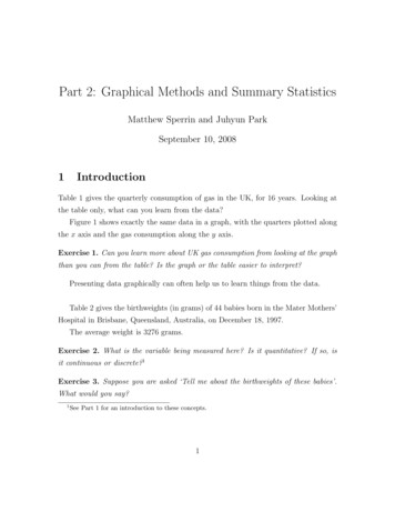
UM2202Main window presentation3Main window presentationAfter launching STM32CubeMonitor-Power (for example from its Windows desktop icon), the application mainwindow is displayed:Figure 3. STM32CubeMonitor-Power main windowSeveral areas are observed in this main window:1.The ribbon (with a dark blue background)2.The two tabs “ACQUISITION & REPLAY” and “ULP BENCH”. By default, the first is shown with its chart area3.The upper-right area containing social network shortcutsNote:When an item is semi-transparent (like the “TAKE CONTROL” button inside the ribbon in STM32CubeMonitorPower main window), this means that it is disabled and clicking on it produces no effect.3.1RibbonThe ribbon contains several controls and information that are valid whatever the tab displayed in the central area: “SELECT BOARD” choice list, used to choose one among the COM ports “TAKE CONTROL” button, to take control over a PowerShield, through the chosen COM port; this button canalso be named “RELEASE CONTROL” (see below) “RESET TARGET”, to reset the connected target MCU once control is taken over the correspondingPowerShield “GET TEMPERATURE” to retrieve the ambient temperature measured on the PowerShield, and display it inthe white box on its right “Firmware version” to display the version of the PowerShield firmware3.2“ACQUISITION & REPLAY” tabThis tab is shown by default when launching STM32CubeMonitor-Power (see STM32CubeMonitor-Power mainwindow).This tab is mainly used to display current measurement in a chart form; those measurements come from aconnected PowerShield (this is called Acquisition mode) or from a file stored locally (this is called Replay mode).UM2202 - Rev 6page 5/29
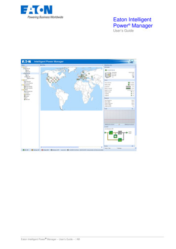
UM2202“ULP BENCH” tabThe “Show Report” button is used to enable the display of the Acquisition Data Report pane below the chart area,giving statistical information on the data displayed in the chart.The gear icon is used to get access to the configuration panes for the two chart axes: time on horizontal(abscissa) axis and current on the vertical (ordinate) axis.The “ADD DATA LOG” button is used to open a file previously saved by STM32CubeMonitor- Power and to loadits data in the chart (Replay mode).The “SAVE GRAPH” button is used to save the data acquired from PowerShield (in Acquisition mode) anddisplayed in the chart area into a file with the “stpm” extension.3.3“ULP BENCH” tabThis tab is not visible by default: click on the dark blue tab item named “ULP BENCH” to see the content of the“ULP BENCH” tab.This tab is used to perform EEMBC ULP Bench tests, displaying in a chart the consumed energy during thosetests, and showing the resulting ULPMark - Core Profile score at the end of the tests.The “ULPBENCH CONFIGURATION” area is used to set the input voltage of the target MCU during the executionof ULP Bench tests, as well as the number of test iterations to be performed.The “ULP BENCH TEST” button is used to launch the test according to the chosen configuration parameters.The “PROGRESS REPORT” area displays information about the ongoing tests.The “ULPMARK-CP” area displays the ULP Bench tests results, with the computed ULPMark - Core Profile score,the currently used voltage, the ambient temperature, as well as the minimum and maximum current values.Figure 4. "ULP BENCH" tab.UM2202 - Rev 6page 6/29
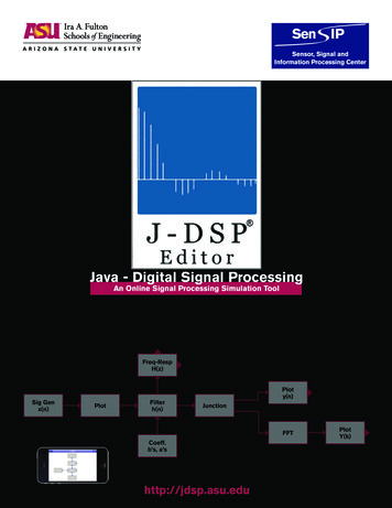
UM2202Social network shortcut area3.4Social network shortcut areaFigure 5. Social network shortcut areaThis area contains five shortcuts to social networks and web pages: The Facebook icon leads to the official STMicroelectronics Facebook page The YouTube icon leads to the official STMicroelectronics YouTube page The Twitter icon leads to the official STMicroelectronics Twitter page The Share icon leads to the ST Community web site The ST icon leads to the official STMicroelectronics web siteUM2202 - Rev 6page 7/29
UM2202How to use STM32CubeMonitor-Power?4How to use STM32CubeMonitor-Power?Figure 6. STM32CubeMonitor-Power start pageAfter launching STM32CubeMonitor-Power, the main window is displayed with the “ACQUISITION & REPLAY”tab shown by default, as seen in STM32CubeMonitor-Power start page.From this start page (also called Idle State), several actions can be performed: Connect to PowerShield (see Section 4.1 ) Show/hide the Acquisition Data Report (see Section 4.6.6 ) Configure acquisition chart X-axis (abscissas) (see Section 4.6.7 ) Configure acquisition chart Y-axis (ordinates) (see Section 4.6.8 ) Load previously saved data into acquisition chart (see Section 4.6.10 ) Select the ULPBench tab (see Section 4.7 )4.1Connect to a PowerShieldTo perform either a current measurement acquisition or an ULPBench test campaign, STM32CubeMonitor-Powermust be connected to a PowerShield and take control of it.To be able to connect STM32CubeMonitor-Power to a PowerShield, the Virtual COM port driver must have beenpreviously installed (see Section 2.2.2 Installing the Virtual COM port driver), and this PowerShield must have itsUSB cable connected to a USB port of the Host machine running STM32CubeMonitor-Power.Once the PowerShield is plugged, it is ready for connection after a couple of seconds. In the upper ribbon ofSTM32CubeMonitor-Power, click on the "SELECT BOARD" choice list, that displays the list of COM ports onwhich PowerShield boards have been detected. Select the COM port corresponding to the PowerShield that youwish to connect.UM2202 - Rev 6page 8/29
UM2202Release control on a PowerShieldFigure 7. COM port selectionOnce a COM port is chosen, the “TAKE CONTROL” button becomes active; click on it to take control over thePowerShield.If taking control is successful, this button becomes “RELEASE CONTROL”, the other buttons of the upper ribbonbecome active, the firmware version area is updated to show the firmware version of the connected PowerShield,a “CONFIGURATION” pane appears in the “ACQUISITION & REPLAY” tab, and the PowerShield LCD shows“Controlled by Host”.From this moment, STM32CubeMonitor-Power is in Connected State.If an error occurs while taking control of the PowerShield, check the selected COM port or the PowerShield USBcable.From the Connected State, several other actions can be performed: Release control on the PowerShield (see Section 4.2 ) Calibrate the PowerShield (see Section 4.3 Calibrate PowerShield) Reset target MCU (see Section 4.4 ) Get ambient temperature (see Section 4.5 ) Configure the PowerShield acquisition parameters (see Section 4.6.1 Configure acquisition parameters) Start acquisition (see Section 4.6.2 ) Show/hide the Acquisition Data Report (see Section 4.6.6 ) Configure acquisition chart X-axis (abscissas) (see Section 4.6.7 ) Configure acquisition chart Y-axis (ordinates) (see Section Section 4.6.8 Configure acquisition chart Y-axis(ordinates)) Launch ULPBench test (see Section 4.7 )4.2Release control on a PowerShieldFigure 8. Release control on a PowerShieldIf STM32CubeMonitor-Power is in Connected State, click on the “RELEASE CONTROL” button of the upperribbon, which deactivates the “RESET TARGET” and the “GET TEMPERATURE” buttons of the upper ribbon.From this moment, STM32CubeMonitor-Power is back in Idle State. However, if some data were present in thechart, they are still visible and STM32CubeMonitor-Power then switches into the Data Available State, whereother actions become possible (see sections below).UM2202 - Rev 6page 9/29
UM2202Calibrate PowerShield4.3Calibrate PowerShieldFigure 9. Calibrate PowerShieldIf STM32CubeMonitor-Power is in Connected, click on the “CALIBRATE" button of the upper ribbon calibrates thePowerShield.4.4Reset target MCUFigure 10. Reset target MCUIf STM32CubeMonitor-Power is in Connected, Acquisition or Data Available states, click on the “RESETTARGET” button of the upper ribbon resets the target MCU.The PowerShield stays connected and data acquisition continues if previously started, allowing, for instance, toperform current measurement during the target MCU start-up phase.4.5Get the ambient temperatureFigure 11. Get ambient temperatureIf STM32CubeMonitor-Power is in Connected State, Acquisition State or Data Available State, click on the “GETTEMPERATURE” button of the upper ribbon, which requests to the PowerShield the ambient temperature. Theresult is displayed (in C) in the white box near this button.UM2202 - Rev 6page 10/29
UM2202Performing a current acquisitionCaution: This temperature is NOT the temperature of the target board under test, but the ambient temperaturemeasured on the PowerShield board.4.64.6.1Performing a current acquisitionConfigure acquisition parametersIf STM32CubeMonitor-Power is in "Connected State" or "Data Available State", a “CONFIGURATION” pane ispresent on the left of the “ACQUISITION & REPLAY” tab, as shown in STM32CubeMonitor-Power start page. Asit can be hidden, click on the blue area on the left of the chart area to make it visible again.Figure 12. Acquisition configuration pane (on the left)This configuration pane is used to specify acquisition parameters: Sampling frequency: PowerShield current measurement frequency choice list (1 Hz, 2 Hz, 5 Hz, 10 Hz, 20Hz, 50 Hz, 100 Hz, 200 Hz, 500 Hz, 1 kHz, 2 kHz, 5 kHz, 10 kHz, 20 kHz, 50 kHz, 100 kHz). Default value is100 Hz.Each measurement sample is sent from the PowerShield to STM32CubeMonitor- Power and is temporarilystored. Acquisition time: time after which the acquisition automatically stops, in a choice list from 0.1 s, 1 s, 10 s,100 s to the “infinite”. It is up to the user to stop the acquisition manually. The default value is 10 s. Current threshold: current threshold (in mA) used to trig events inside the PowerShield, when measuredcurrent exceeds this limit, like switching on a LED or setting a hardware signal (please refer to thePowerShield User Manual for more details); there is no effect on STM32CubeMonitor-Power. The maximumvalue is 50 mA for the X-NUCLEO-LPM01A dedicated expansion board, and 150 mA for the Energy Meterof the STM32L562E-DK Discovery kit. The default value is 1 mA. Trigger source: the source of the trigger that is used to start the acquisition; it can be from internal softwareor an external interrupt (D7 pin). The default value is SW.UM2202 - Rev 6page 11/29
UM2202Performing a current acquisition Trigger delay: time to wait after the trigger event occurred, before really starting the acquisition. Themaximum value is 30000 ms. The default value is 1 ms.Input voltage: supply voltage (in mV) applied to the target MCU board. Allowed values are between 1800 mVand 3300 mV. The default value is 3300 mV.Functional mode:–Optim(ized): mode focusing on having accurate current measurements from 100 nA up to 50 mA XNUCLEO-LPM01A dedicated expansion board, and from 300 nA to 150 mA for the Energy Meter of theSTM32L562E-DK Discovery kit for any sampling frequency, but some artifacts are seen in some caseswhere very low and very high current measurements coexist.–High: mode focusing only on high currents, from 30 μA to 50 mA for the X-NUCLEO-LPM01Adedicated expansion board, and form 90 μA to150 mA for the Energy Meter of the STM32L562E-DKDiscovery kit, avoiding optimized mode current artifacts, but values being inaccurate below 30 μA forthe X-NUCLEO-LPM01A dedicated expansion board, and below 90 μA for the Energy Meter of theSTM32L562E-DK Discovery kit; only valid only for 50 kHz and 100 kHz sampling frequencies.Figure 13. Input VoltageThose parameters are taken into account only when starting a new acquisition (see Section 4.6.2 ).If one parameter is outside the allowed range, it is indicated by a red rectangle, and it is impossible to launch anew acquisition until a valid value is entered.Erase all data in a parameter input field to show the range of allowed values.4.6.2Start acquisitionFigure 14. Start acquisitionIf STM32CubeMonitor-Power is in "Connected State" or "Data Available State", it is possible to (re-)startacquisition of current measurements by pressing the “START ACQUISITION” button at the bottom of the"CONFIGURATION” pane.STM32CubeMonitor-Power then switches into the "Acquisition State", clears the chart data if any (these are lost ifthey have not been previously saved), and launches the acquisition process by applying the acquisitionparameters values present in the "CONFIGURATION” pane, that are then inaccessible.The “START ACQUISITION” button becomes “STOP ACQUISITION”. Data samples are received from thePowerShield, stored in a temporary location and some are displayed in the chart area in real-time to lowergraphical load. The Acquisition Data Report values (if visible) are updated in real-time according to the receiveddata (min/max/average current and energy values).In the Acquisition State, the only possible actions are to reset the target MCU (see Section 4.4 ), get the ambienttemperature (see Section 4.5 ) or stop the current acquisition (see Section 4.6.3 ).UM2202 - Rev 6page 12/29
UM2202Performing a current acquisition4.6.3Stop acquisitionFigure 15. Stop acquisitionTo stop the acquisition process before the end of the planned acquisition time, or when the acquisition time is setto “infinite”, press on the “STOP ACQUISITION” button, which becomes “START ACQUISITION” again.Acquisition parameters become accessible.If the acquisition time is not “infinite”, and the “STOP ACQUISITION” button is not pressed, the acquisitionprocess automatically stops at the end of the acquisition time, and STM32CubeMonitor-Power proposes to savethe acquired data in a dedicated file (see Section 4.6.9 ).Acquired data is still visible in the acquisition chart and STM32CubeMonitor-Power then switches into the DataAvailable State, where other actions become possible (see below).4.6.4Zoom in and zoom out in the acquisition chart areaIf STM32CubeMonitor-Power is in Data Available State, it is possible to zoom in and out inside the chart area: Use the left mouse button and move the mouse to create a blue rectangle used for zoom-in selection. If themouse pointer is above one of the axis areas, it selects the full data width or height.Figure 16. Zoom in acquisition Use the mouse wheel forward to gradually zoom-in, centered on the mouse position. If the mouse pointer isabove one of the axis areas, only this axis is zoomed-in.Use the mouse wheel backward to gradually zoom-out, centered on the mouse position. If the mouse pointeris above one of the axis areas, only this axis is zoomed-out.Press the “ShowAll” button in the upper-right corner of the chart area to zoom out on the full data range.When zooming in or out, the “SELECTED TIME FRAME” area of the "Acquisition Data Report" (if visible) isupdated to adapt to the time frame visible in the chart area (min/max/average current and energy values).Note:UM2202 - Rev 6Data samples are reloaded from temporary storage for each zoom-in or zoom-out operation, therefore someloading lags may occur, especially for high sampling frequencies.page 13/29
UM2202Performing a current acquisition4.6.5Moving in the acquisition chart areaIf STM32CubeMonitor-Power is in Data Available State, it is possible to slide data inside the chart area bypressing the right mouse button and moving the mouse, but it is not possible to slide beyond the actual datalimits.Data is reloaded after the mouse button is released, therefore some loading lags may occur.When moving into the chart area, the “SELECTED TIME FRAME” area of the Acquisition Data Report (if visible)is updated to adapt to the time frame visible in the chart area (min/max/average current and energy values).4.6.6Show and hide the acquisition data reportFigure 17. Acquisition data report (below the acquisition chart)If STM32CubeMonitor-Power is in "Connected State" or "Data Available State", it is possible to show or hide theAcquisition Data Report pane located below the Acquisition chart, by clicking on the “Hide Report” / “ShowReport” button (number 8 in Acquisition data report (below the acquisition chart)) in the upper-right corner of thechart area.This Acquisition Data Report pane is divided in two parts: The “FULL” area gives statistical information on current measurements and energy computation for the fulldata range, even if not currently visible in the acquisition chart The “SELECTED TIME FRAME” area gives statistical information on current measurements and energycomputation, corresponding only to the time frame visible in the acquisition chart (see time boundaries onthe X-axis)4.6.7Configure acquisition chart X-axis (abscissas)If STM32CubeMonitor-Power is in Idle State, "Connected State" or "Data Available State", it is possible toconfigure acquisition chart X-axis (also called abscissas), by clicking on the gear icon (number 9 in the Acquisitiondata report (below the acquisition chart)) located in the upper-right corner of the acquisition chart, and selectingthe abscissa axis item. This opens the X-axis configuration pane.UM2202 - Rev 6page 14/29
UM2202Performing a current acquisitionFigure 18. X-axis configurationThe upper area is used to configure the chart width, timeframe visible into the acquisition chart area. This valuecan be changed using the slider on the left, or the arrow buttons for better precision. As soon as a change isdetected, the “RELOAD” button becomes active, to request data reloading into the chart to apply this change andcheck its impact on the chart.The lower area is used to choose the position of the X-axis, at the bottom or the top of the acquisition chart area,with an immediate effect.Clicking outside of this pane closes it.Note:Window Size setting is directly linked to the Acquisition Time setting present in the “CONFIGURATION” pane.Changing Acquisition Time automatically changes Window Size. However, changing "Window Size" does notchange "Acquisition Time". When "Acquisition Time" is set to "infinite", "Window Size" is set to 10 s.Note:If "Window Size" setting is lower than "Acquisition Time" setting, the visible time frame "slides" to always showthe latest acquired data until the acquisition is stopped (automatically or manually).4.6.8Configure acquisition chart Y-axis (ordinates)If STM32CubeMonitor-Power is in Idle State, "Connected State" or "Data Available State", it is possible toconfigure acquisition chart Y-axis (also called ordinates axis) by clicking on the gear icon (number 9 in Acquisitiondata report (below the acquisition chart)) located in the upper-right corner of the acquisition chart, and selectingthe ordinate axis item. This opens the Y-axis configuration pane.Figure 19. Y-axis configurationThe upper area is used to configure the chart height, the span of the current values. Minimal and maximal valuescan be changed using the slider or the arrow buttons of “Min” and “Max” boxes for better precision.The “Dynamic Range” checkbox is used to activate the automatic adaptation of the Y-axis min and maxboundaries to the data values loaded into the acquisition chart. When this box is checked, it is impossible to setthose boundaries manually (see above).The lower area is used to choose the position of the Y-axis, at the left or the right of the acquisition chart area.Clicking outside of this pane closes it.4.6.9Save acquisition dataFigure 20. Save acquisition dataIf STM32CubeMonitor-Power is in Data Available State after an acquisition procedure, it is possible to save theacquired data samples into a dedicated file by clicking on the “SAVE GRAPH” button.UM2202 - Rev 6page 15/29
UM2202Performing ULPBench testsDoing this opens a file chooser window. The saved file has the “stpm” extension.4.6.10Load previously saved data into acquisition chartFigure 21. Load previously saved data into acquisition chartIf STM32CubeMonitor-Power is not in Connected State (no control on an X-NUCLEO-LPM01A), it is possible toload previously saved acquisition data by clicking on the “ADD DATA LOG” button. Doing this opens a file chooserwindow, where a file with “stpm” extension must be selected.Once an “stpm” file is chosen to be opened, its data is read and loaded into the Acquisition tab chart (previousdata are cleared before this loading). No action can be performed until the end of data loading. By default, thechart shows the whole scope of the loaded data: both X-axis and Y-axis are adjusted to maximize data visibility. Aloading progress indicator is displayed during the loading operation.Figure 22. Loading progress indicatorThe Acquisition Data Report (if visible) is updated according to the received data (min/max/average current andenergy values).From this moment, STM32CubeMonitor-Power is in Data Available State.The firmware version area of the upper ribbon is also updated to show the version of the X-NUCLEO-LPM01Afirmware that has been originally used to perform the acquisition of the loaded data.From this Data Available State, several other actions can be performed, such as zooming-in / -out or moving inthe acquisition chart area or configuring X- and Y-axis (see above).4.7Performing ULPBench testsWhen STM32CubeMonitor-Power is in Idle State (not connected to an X-NUCLEO-LPM01A), click on the darkblue tab item named “ULP BENCH” to see its content.The only possible action here is to show or hide “ULPBench Data Report” pane (see Section 4.7.4 ). The contentof the "ULPBench Configuration" and "Report area" on the left of the chart area is inactive.UM2202 - Rev 6page 16/29
UM2202Performing ULPBench testsWhen STM32CubeMonitor-Power is in Connected State (see Section 4.1 ), the content of the ULPBenchConfiguration and Report area becomes active as shown in ULPBENCH tab in "Connected State". It is possible toconfigure ULPBench parameters (see Section 4.7.1 ), launch ULPBench tests, follow Progress Report (seeSection 4.7.2 ) and see the ULPMark results after the tests (see Section 4.7.3 ).Figure 23. ULPBENCH tab in "Connected State"4.7.1Configure ULPBench parametersWhen STM32CubeMonitor is in Connected State, it is possible to configure ULPBench parameters.Figure 24. ULPBench configuration Note:UM2202 - Rev 6Input voltage: supply voltage (in mV) applied to the target MCU board. Allowed values are between 1800 mVand 3300 mV. The default value is 3000 mV. Only 100 mV steps via the arrow keys are possible.Number of iterations: number of ULPBench test iterations to perform to compute a median result over thoseiterations. Values are between 1 and 15. The default value is 1. Changes are allowed only one by one viathe arrow keys.The duration of an ULPBench test iteration is 10 seconds.Those parameters are taken into account only when starting a new ULPBench test (see Section 4.7.2 ).page 17/29
UM2202Performing ULPBench tests4.7.2Launch ULPBench testFigure 25. ULPBench testWhen STM32CubeMonitor is in "Connected State", it is possible to launch the ULPBench test by clicking on the“ULP BENCH TEST” button.STM32CubeMonitor-Power then switches into the "ULPBench Test State", clears the chart data if any, andlaunches the ULP Bench test process by applying the ULP Bench configuration parameters (see Section 4.7.1 ).In the "ULPBench Test State", no action is possible until the end of the test process.Caution: To perform properly the ULPBench test, there must be a firmware loaded and running into the targetboard. If the target board is an STMicroelectronics Nucleo board, check www.st.com website to get this firmwareand to load it.Just after launching the ULPBench test, a board initialization phase is needed to avoid perturbations on currentmeasurements.During this phase, awaiting animation is displayed in the ULPMARK-CP area:Figure 26. Board initialization phaseWhen this board initialization phase is finished, the data samples of the current ULPBench test iteration arereceived from the PowerShield and displayed in the chart area in real-time. Chart area is cleared between twoiterations, thus only the data samples of the last iteration are visible at the end of the ULPBench test.During the entire ULPBench test, a percentage of progression is displayed in the ULPMARK-CP area and the"Progress Report" console informs of the ULPBench test progression and gives the ULPMark estimation for eachiteration.Figure 27. Progress reportUM2202 - Rev 6page 18/29
UM2202Performing ULPBench testsFigure 28. ULPBench iterationWhen the ULPBench test is finished, the ULPBench test result is shown in the ULPMARK-CP area (see Section4.7.3 ). The last iteration data samples are shown in the chart area and STM32CubeMonitor-Power switches intothe "ULPBench Data Available State", where other actions become possible (see below).4.7.3ULPMark resultsWhen the ULPBench test is finished, several pieces of information are made available into the ULPMARK-CParea.Figure 29. ULPMark results 4.7.4Score: ULPMark Core Profile scoreLeave mouse pointer a few seconds on the information icon to know how this
To uninstall the STMicroelectronics USB Virtual COM port driver, follow the steps below: Open the Windows Control pane Select Programs and Features to display the list of programs installed on your computer Right-click on "Virtual Com port driver" from STMicroelectronics publisher and select the uninstall function UM2202 Installing