Transcription
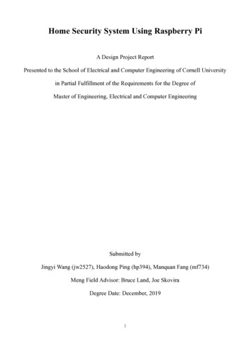
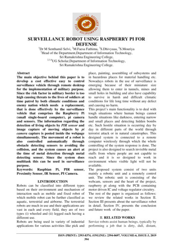
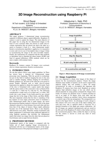
International Journal of Computer Applications (0975 – 8887)Volume 181 – No.4, July 20183D Image Reconstruction using Raspberry PiShruti RayajiUdaykumar L. Naik, PhDM.Tech student, VLSI Design & EmbeddedSystemsDepartment of Electronics & CommunicationsK.L.E. Dr. MSSCET, Belagavi, KarnatakaProfessor, Department of Electronics &CommunicationsK.L.E. Dr. MSSCET, Belagavi, KarnatakaABSTRACTThis paper proposes 3 dimensional image reconstructioncaptured of different objects angled differently. Raspberry Picamera is used to capture the images. The main objective ofthis paper lies in using the two dimensional images in theform of cross sectional slides also known as multi slice-tovolume registration that are placed one above the other in amesh to re-project it back to a three dimensional model.Iterative reconstruction algorithm is applied as it is insensitiveto noise and even in case of incomplete data or image it helpsin reconstructing the image in the most favorable manner.Finally, the experiments are compared with the other methodsor algorithms such as Speeded up robust feature (SURF) andSum of squared differences (SSD) methods which are farmore complex with nominal clarity.KeywordsRaspberry Pi; features; camera; 2d images; cross sectional;slice-to-volume registration; Iterative reconstruction.1. INTRODUCTIONWe ask that authors follow some simple guidelines. In Therehas always been a demand for 3-dimensional imageprocessing since beginning. With the growth in technologynot just in the field of medical imaging but also in the areasuch as satellite imaging, military imaging for surveillance,Robotic guidance etc. the need of the same has even grown togreater heights. Methods such as multi slice-to-volumeregistration are applied to obtain the required 3d model. Eachof the slice is formulated with a sparse matrix that mergeswith the sparse matrix of the consecutive slice to blend all the1’s with the 1’s while the 0’s with the 0’s. The followingconsideration is made such as 0 as black and 1 as white. Thisresults into a grey image. It also holds good for any coloredimage that lies in the range of Red, Green, and Blue (RGB).The most important criteria that lies here is matching of thekey features of every input consecutive slices to formulate afinal 3dimensional model. Due to multi images, the stereoReconstruction Pipeline method is followed. Each of the planeobtained is placed at a fixed distance from each other and alsofrom that of the object of interest. Hence depth calibrationbecomes one of the important factor. There is also disparityshift between every plane. Therefore, feature localization anddepth computation is performed using traditional approach ofusing Epipolar geometry that describes the fundamentalmatrix that relates one image from the other that are placed atfixed distance and an angle between them[1].Figure 1- Block diagram of 3D image reconstruction2.1 Image AcquisitionIt is very important to obtain clear images of the object ofinterest for the reconstruction purpose. Clearer the imageobtained, large number of features can be used to match fromadjacent images that will produce a dense 3D imagereconstruction. In order to accomplish this important taskRaspberry Pi cameras have been used. Raspberry pi cameracaptures high definition images at fast rate which can bealtered manually by using python command [6]. Images fromtotally 10 cameras are obtained. It has 5 cameras attached ontop at an angle of 30 degree from each other and theremaining 5 cameras are attached below whose arrangementis a mirror copy of the top arrangement. The arrangement is asshown in the figure below. An advantage of such a design isthat cameras will cover every part of the object making sureeach and every side is captured which is necessary for adetailed formation of the depth and camera calibrations. Allthe 10 images are captured simultaneously and are stored inthe SD card of the Raspberry Pi which is then further used forthe reconstruction purpose. Here, neither the object is movingnor the camera is moved to avoid any kind of noiseinterruption.2. PROPOSED METHODFundamental matrix of the images is computed with thefurther aid of depth mapping. Image reconstruction isperformed with the use of fundamental matrix of the image.Detailed discussion of the proposed technique is given below.8
International Journal of Computer Applications (0975 – 8887)Volume 181 – No.4, July 2018Figure 5- The intrinsic parameters include the opticalcenter and focal length of the camera. . (1)where, w is the scale factor.Figure 2- Skeletal representation of 10 cameras.The following image gives the skeletal representation of thesame.Left hand matrix indicates the image pointsRight hand matrix indicates world pointsP indicates the camera matrix nd is given by . (2)Extrinsic Parameters basically consists of rotation andtranslation. While intrinsic parameters include focal length,optical center and skew coefficient. The intrinsic matrix isgiven by: (3)Figure 3- Representation of multiview of 10 cameras.2.2 Camera Calibrationwhere, (fx, fy ) – are focal length in pixels and (Px , Py ) – aresize of pixels world units.The pin hole camera model given below is based on theprinciple of collinearity. [1]2.3 Rectification and feature extractionWe follow the ORB (Oriented FAST and rotated BRIEF)algorithm which is a fast and a robust method of featuredetector that was presented by Ethan Rublee et al. in 2011.This fusion of FAST key point detector and BRIEF descriptoris used to improve the performance of the output 3d image bycertain modifications. This method is considered as anefficient alternative to Scale-invariant feature transform(SIFT) or Speeded up robust feature (SURF) in 2011 also withrespect to computation cost, matching performance and alsopatents it’s a very good alternative. It first starts with the useof Features from accelerated segment test (FAST) to find thekey points and then applies Harris corner measure to find topN points among the images. It also produces multiscalefeatures by the use of pyramid.Figure 4- Pin hole cameraAs seen from the model a point in the space with coordinatesis mapped with the point on the image plane. Hence therelationship between space coordinates and image plane as:x PX with P being the projection matrix. Camera parametersare divided as intrinsic, extrinsic and distortion coefficients.With the help of the help of the available 2D and 3D imagepoints we can estimate the camera parameters. The diagrambelow explains clearly that the camera parameters arerepresented in a 4-by-3 matrix called the camera matrix. Herethe calibration algorithm is used to calculate the cameramatrix using the extrinsic and intrinsic parameters. A virtualimage plane is mapped by this matrix by using the 3D worldscene. [1]It computes the intensity weighted centroid of the patch at thecenter. The direction of the vector from this corner point tocentroid gives the orientation. To make these rotationinvariance better, moments are computed using x and y thathave to be in a circular region of radius r, where r is the sizeof the patch. For every precompiled Binary RobustIndependent Elementary Features (BRIEF) pattern itconstructs a lookup table and until the key point orientation Ɵremains consistent across views, the exact set of pointswill be used to compute its descriptor. One of the mostimportant features of the BRIEF is that each bit feature carriesa large variance and mean near 0.5 which makes a featureeven more discriminative as it responds differently to inputs.9
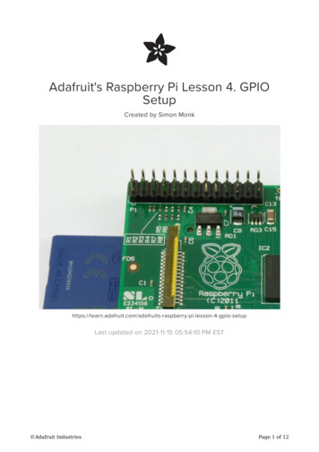
International Journal of Computer Applications (0975 – 8887)Volume 181 – No.4, July 20182.4 Map the disparityThis helps in the mapping of the depth with the help of thestereo images. Here the concept of retinal disparity is used toobserve the horizontal separation or the parallax that producesan illusion of one continuous image.Figure 6- Depth mappingFrom the above equivalent triangle the following equation fordisparity is derived as follows:Disparity x-x’ Bf/Z (4)where x and x’ represents the distance between points inimage plane that corresponds to that of the scene points in the3D and their corresponding camera center. B denotes thedistance between two cameras and f the focal length of thecamera that is known. Hence we can deduce that the depth ofa point in a scene is inversely proportional to the difference indistance o corresponding image points and their respectivecamera centers. This in turn helps to evaluate the depth of allthe pixels in an image [2].2.5 3-Dimensional plot using fundamentalmatrixFigure 7- Point correspondence geometry An Epipolar plane is a plane that contains thebaseline as sown in the figure below. It includes oneparameter family of Epipolar planes The Epipolar planes intersects the left image planewith that of the right planes in Epipolar lines, anddefines the correspondence between the lines [8].Fundamental matrix denoted by F is nothing but an algebraicrepresentation of Epipolar geometry. Here, Epipolar geometryis the geometry of the intersection of the image planes withthe pencil of planes having the line joining the camera centersknown as the baseline. It helps in finding the correspondingpoints in the stereo matching [7].From the figure below, a point X in 3-space is imaged in twoviews, at x in the first and x’ in the next. The relationshipbetween all of these is that they are coplanar. Let’s denote thisplane as π. From the figure we can note that the rays projectedfrom x and x’ intersect at X, and the rays are coplanar, lyingin π. It is one of the most important property that is of mostsignificance in searching for a correspondence.Figure 8- Representing the feature matchingFigure 9- Converging cameras and Fundamentalmatrix F10
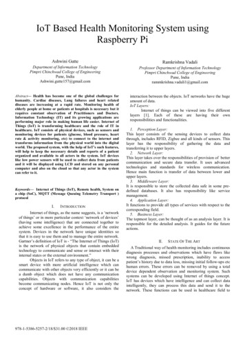
International Journal of Computer Applications (0975 – 8887)Volume 181 – No.4, July 2018For the geometric derivation of a fundamental matrix, the twoimages can be decomposed into two steps.The first being that the point x is mapped to a correspondingpoint x’ on the other image that lies on the Epipolar line l’.Here x’ is known as the potential match for the point x. Hencefundamental matrix can be written asFigure 11- 3D reconstruction of images along withdepth mappingFigure 10- Images obtained through fundamentalmatrix at 30 and 60 degree angle.2.6 3-Dimension reconstruction and depthFrom the above mentioned methodology a final 3Dreconstruction mesh was applied on the figures captured.Following are the results of the 3D images obtained.3. EXPERIMENTAL RESULTS2D images of cashew and sharpener that are captured atdifferent angles are shown in the figure 14 and figure 15respectively. The following tabulations have been performedthat gives the respective values of different parameters ofthese images. Such as aspect ratio which describes theproportional relationship between the width and height of animage. In the table1 we compute the aspect ratio of cashewsand sharpener which is expressed as two numbers separatedby a colon given as x : y. Similarly, it is evident from the tablethat the total area of the images is computed using theirrespective solidity, hull area, extent and perimeter values.These parameters prove to be of great importance in thereconstruction of the 3 dimensional image. Below are resultsand the outcome of the computation.Figure 12- 3D image reconstruction of the images at300.Figure 13- 3D image reconstruction of the images at600.11
International Journal of Computer Applications (0975 – 8887)Volume 181 – No.4, July 2018Table 1AspectImagesAreaEquiPerimeterExtentHull AreaSolidityRatioDiameterImage Cashew -15.59.071.00.345.51.02.65Image Cashew -213549530.71.460.62155090.8131.3Image Cashew -32.05.661.00.222.01.01.56Image Cashew -413.016.462.00.4114.50.894.07Image Sharpner -16.515.410.250.416.51.02.88Image Sharpner -23650.5252.470.70.773910.50,9368.2Image Sharpner -37.016.00.250.447.01.02.99Image Sharpner -42024.0202.430.440.832242.50.950.76formation of fundamental matrix as discussed above with thehelp of 2D images has produced good results. For the imagereconstruction two different objects are considered. As seenfrom the table the area remains unique for different objects atdifferent angle. As seen for cashew the area ranges between2mm2 to 13549mm2 at varied angles. Similarly, for asharpener it ranges between 6.5mm2 to 3650mm2. With theimage sequencing of the fundamental matrix that is deduced itis possible achieve a 3D reconstruction up to an accuracy rateof 60% to 70%.5. ACKNOWLEDEGMENTFigure 14- 2D Images of Cashew captured at differentangleI take this opportunity to thank my college KLE’s.Dr.M.S.Sheshgiri college of Engineering & Technology. Iwould like to extend my profound thanks to Mr. Sasisekar; thefounder of the company Nanopix pvt ltd, Hubli, withoutwho’s support and concern this work would not have beencompleted.6. REFERENCES[1] Zhang, Z. “A Flexible New Technique for CameraCalibration.” IEEETransactions on Pattern Analysisand Machine Intelligence. Vol. 22, No. 11, 2000, pp.1330–1334.[2] Heikkila, J., and O. Silven. “A Four-step CameraCalibration Procedurewith Implicit ImageCorrection.” IEEEInternationalConferenceonComputer Vision and Pattern bouguetj/calib docfor,Camera Calibration[4] Trucco, emanuele and verri, “Introductory Techniques for3D Computer vision”.[5] Viral H.Borisagar, Mukesh A.Zaveri, “A Novel Segmentbased Stereo Matching algorithm for Disparity mapGenerationInternational conference on Computer andSoftware Modeling, Volume 14, 2011.Figure 15- Images of Sharpener captured at differentangle4. CONCLUSION AND FUTURE SCOPEAuto image analysis is a complex task. Real time imagecapturing and converting them into 3D image is a very tedioustask as it involves limiting of the tolerable error. In such asituation attempting to extract features is most intricateprocedure. However, with the use of depth mapping and[6] Sahitya S, Lokesha H, Sudha L K “Real time applicationof Raspberry Pi in compression of images”, 2016 IEEEInternational Conference on Recent Trends inElectronics, Information & Communication Technology(RTEICT).[7] Luis Gerardo de la Fraga and Israel Vite Silva “Direct 3DMetric Reconstruction from Two Views UsingDifferential Evolution”, 2008 IEEE Congress onEvolutionary Computation (IEEE World Congress on12
International Journal of Computer Applications (0975 – 8887)Volume 181 – No.4, July 2018Computational Intelligence)2008 IEEE Congress onEvolutionary Computation (IEEE World Congress onComputational Intelligence)IJCATM : www.ijcaonline.org[8] Chuan Li, injin Zheng, Chuangyin Dang and HongjunZhou “A Method of 3D Reconstruction from ImageSequence”, 2009 2nd International Congress on Imageand Signal Processing.13
Raspberry Pi cameras have been used. Raspberry pi camera captures high definition images at fast rate which can be altered manually by using python command [6]. Images from totally 10 cameras are obtained. It has 5 cameras attached on top at an angle of 30 degree from each other and the