Transcription
Cypress EZ-USB FX3 SDKEZ-USB Suite User GuideVersion 1.3.4Cypress Semiconductor198 Champion CourtSan Jose, CA 95134-1709Phone (USA): 800.858.1810Phone (Intl): 408.943.2600http://www.cypress.comEZ-USB Suite User Guide, Version 1.3.41
CopyrightsCopyright 2017-18 Cypress Semiconductor Corporation. All rights reserved.EZ-USB, FX3, FX3S, CX3, FX2G2 and GPIF are trademarks of Cypress Semiconductor. All other trademarks or registeredtrademarks referenced herein are the property of their respective owners.The information in this document is subject to change without notice and should not be construed as a commitment byCypress. While reasonable precautions have been taken, Cypress assumes no responsibility for any errors that mayappear in this document. No part of this document may be copied or reproduced in any form or by any means without theprior written consent of Cypress. Made in the U.S.A.DisclaimerCYPRESS MAKES NO WARRANTY OF ANY KIND, EXPRESS OR IMPLIED, WITH REGARD TO THIS MATERIAL,INCLUDING, BUT NOT LIMITED TO, THE IMPLIED WARRANTIES OF MERCHANTABILITY AND FITNESS FOR APARTICULAR PURPOSE. Cypress reserves the right to make changes without further notice to the materials describedherein. Cypress does not assume any liability arising out of the application or use of any product or circuit described herein.Cypress does not authorize its products for use as critical components in life-support systems where a malfunction orfailure may reasonably be expected to result in significant injury to the user. The inclusion of Cypress’ product in a lifesupport systems application implies that the manufacturer assumes all risk of such use and in doing so indemnifiesCypress against all charges.License AgreementPlease read the license agreement during installation.EZ-USB Suite User Guide, Version 1.3.42
Contents1EZ-USB Suite . 41.1 Introduction . 41.2 IDE Features . 42Creating an FX3 Firmware Project . 52.1 Starting the EZ-USB Suite IDE . 52.2 Creating the Project . 62.3 Creating a New Project Based on Templates . 112.4 Using the FX2LP Firmware Templates . 133JTAG Debugging of Firmware Projects . 153.1 Debugging using Segger J-Link . 153.2 Debugging with OpenOCD . 224CX3 Configuration Utility . 274.1 Introduction to the CX3 device . 274.2 CX3 MIPI CSI-2 interface . 284.3 Configuring the CX3 Device . 314.4 Using the CSI Configuration Utility. 334.5 GPIF-II interface on the CX3 . 45EZ-USB Suite User Guide, Version 1.3.43
1EZ-USB Suite1.1IntroductionEZ-USB Suite is the integrated development environment provided by Cypress forfirmware development and debugging using the EZ-USB FX3 and associatedparts.EZ-USB Suite is based on the standard Eclipse Kepler IDE for C/C Developers,and provides a few customizations that are FX3 device family specific.1.2IDE FeaturesThe EZ-USB Suite IDE provides firmware development and debugging support forFX3 applications. It also provides a mechanism to create new FX3 firmwareprojects, and plug-ins for through which other FX3 applications such as ControlCenter and GPIF-II Designer can be accessed.The IDE is integrated with the GNU ARM tool-chain for firmware compilation,linking and debugging. The ARM GNU Eclipse plug-in is used for managed buildsand debugging.The following chapters provide more detailed description on the IDE features.EZ-USB Suite User Guide, Version 1.3.44
2Creating an FX3 Firmware ProjectThis chapter outlines the steps involved in creating a FX3 firmware application,using the GpifToUsb project from the SDK as a reference.2.1Starting the EZ-USB Suite IDELaunch the EZ-USB Suite IDE by following the “All Programs - Cypress - Eclipse- EZ USB Suite” path from the Start Menu.Figure 2-1: Workspace Selection DialogThe IDE will prompt for a Workspace to be opened. If you have already created aworkspace, select it from the dropdown box. Otherwise, provide the path where thenew workspace has to be created and Click OK.EZ-USB Suite User Guide, Version 1.3.45
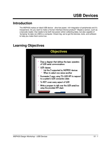
2.2Creating the ProjectThe easiest way to create a new FX3 firmware project under the Eclipse IDE, is toimport an existing project and make changes to it.1. Choose the Import option under the File menu to bring up the Import optionswindow. Choose “Existing Projects into Workspace” from the “General”group.Figure 2-2: Project Import Dialog2. In the “Browse for Folder” window that pops up, navigate into thefirmware/basic examples/cyfxgpiftousb folder in the FX3 SDK installation.EZ-USB Suite User Guide, Version 1.3.46
Figure 2-3: Folder Browse Dialog3. Select the “Copy projects into workspace” option in the Import window, sothat we get a new copy of the source files that can be modified.EZ-USB Suite User Guide, Version 1.3.47
Figure 2-4: Import Projects Dialog4. If desired, right-click the project name and use the “Rename” option torename the project. The respective source files in the project can also berenamed as desired. If the header files are renamed, references to theheader file in the source files will need to be updated.EZ-USB Suite User Guide, Version 1.3.48
Figure 2-5: EZ USB Suite Eclipse Based IDE5. Add additional source files as required. This can be done in one of twoways:a. Right-click the project name and select the “New - Header File” or“New - Source File” option as appropriate.EZ-USB Suite User Guide, Version 1.3.49
Figure 2-6: Adding new source files to a projectb. Copy the file into the project folder inside the workspace and use theRefresh (F5 key) option to make it visible in the project.6. The build settings for the project will already be functional. Right-Click on theproject name and use the “Properties” menu item to view and modify thebuild settings.7. Build the project to verify that the project import and renaming is successful.EZ-USB Suite User Guide, Version 1.3.410
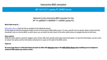
2.3Creating a New Project Based on TemplatesAnother way to create a new FX3 firmware project is to use the Create Projectbased on Templates option provided by EZ-USB Suite.1. Select the New - Project option from the File menu.Figure 2-7: Selecting the New Project Menu Item2. Choose the “Cypress - FX3 Project” option from the resulting popupwindow and click on “Next”.EZ-USB Suite User Guide, Version 1.3.411
Figure 2-8: Choosing project type to be created3. Three project templates are provided. The cyfx3bootappgcc templatecreates a project based on the FX3 boot library. The cyfxbulksrcsinktemplate creates a project that does not include a GPIF-II configuration. Theslfifoasync template creates a project that includes a GPIF-II configuration.Select the “Create the Project using one of the Templates” checkbox, selectthe desired template, provide a name for the project; and click “Finish” tocreate the project.EZ-USB Suite User Guide, Version 1.3.412
Figure 2-9: Creating the template based project2.4Using the FX2LP Firmware TemplatesThe ezUsbSuite also integrates SDCC compiler suite based plug-ins for build of firmware targetingthe FX2LP device which has an 8051 MCU core.To use the ezUsbSuite to develop firmware for FX2LP, you will first need to download and install theSDCC compiler suite. The latest release version (3.6.0) for Windows platforms can be found c-win64/3.6.0/ (for Windows /sdcc-win32/3.6.0/ (for Windows 32-bit)2.4.1Importing the FX2LP Firmware TemplateThe SDK includes only one FX2LP template project which is a bulkloop (data loopback using Bulkendpoints) application. Use the File New Project menu option and select the FX2LP Projectoption in the dialog.Select the Create the project using one of the Templates check-box, select the Bulkloop SDCCproject, name the project as desired in the text box and select Finish to create a copy of thetemplate project.EZ-USB Suite User Guide, Version 1.3.413
You can use the Project Build Project menu option to compile the code and generate the HEXfile.Note: The SDCC compiler and assembler syntax is different from the syntax used by the ARM (Keil)uVision IDE. You cannot directly compile uVision based FX2LP projects using this tool-chain and willhave to port the code to SDCC.EZ-USB Suite User Guide, Version 1.3.414
3JTAG Debugging of Firmware ProjectsThe ARM9 core on the FX3 and related devices support the standard ARM JTAGTAP block and all of the JTAG pins are made available on the device package. Thismeans that any standard JTAG debugger and tools can be used to debug FX3firmware projects.The following sub-sections provide instructions on how the Segger J-Link DebugProbe and the Cypress CY7C65215 USB serial device can be used for debuggingfirmware projects. Similar sequences can be followed when using other debugprobes.3.1Debugging using Segger J-LinkThe following procedure can be used to debug FX3 projects from the Eclipse IDEon all supported platforms (Windows, MacOS and Linux).Download and install the latest J-Link GDB Server software from the Segger webpage: https://www.segger.com/jlink-gdb-server.htmlThe command line version of the GDB server program is used for the followingsteps.EZ-USB Suite User Guide, Version 1.3.415
1. Select and right-click on the project to be debugged, and select the “DebugAs - Debug Configurations ” option.Figure 3-1: Creating debug configuration: StartEZ-USB Suite User Guide, Version 1.3.416
2. In the Debug Configurations popup window, right-click the “GDB Segger JLink debugging” option and select “New”.Figure 3-2: Creating debug configuration: Segger J-Link3. A “ ProjName Debug” configuration will be created. The settings for theconfiguration need to be entered as below.EZ-USB Suite User Guide, Version 1.3.417
4. No changes are required under the “Main” tab.Figure 3-3: Creating debug configuration: Main tabEZ-USB Suite User Guide, Version 1.3.418
5. On the “Debugger” tab, browse and select the path to the J-Link GDB Serverexecutable, specify “ARM9” as the Device Name and select JTAG as thedebug interface. Please note that the {cross prefix} variable must be set toarm-none-eabi- in some cases if the default settings don’t work.Figure 3-4: Creating debug configuration: Debugger tabEZ-USB Suite User Guide, Version 1.3.419
6. On the “Startup” tab, disable the “Enable flash breakpoints”, “Enablesemihosting” and “Pre-run reset and halt” options using the correspondingcheckboxes.Figure 3-5: Creating debug configuration: Startup Tab7. Click on “Apply” to save settings, and then click on “Debug” to startdebugging.EZ-USB Suite User Guide, Version 1.3.420
8. If a “Confirm Perspective Switch” popup window (as shown below) appears,select “Yes” to switch to the Debug perspective. The “Remember mydecision” checkbox can be ticked to prevent this popup from appearing insubsequent debug sessions.Figure 3-6: Creating debug configuration: Perspective switch9. Execution stops at the “main ()” function. Additional breakpoints can beplaced at this stage, and the Resume, Step Into or Step Over actions can beused to run through the code.Figure 3-7: Debug session stopped at breakpointEZ-USB Suite User Guide, Version 1.3.421
10. Click on “Terminate” to stop the debug session.3.2Debugging with OpenOCDOpen On-Chip Debugger (OpenOCD) is an open source debugger implementationthat supports a variety of debugger probes. The CY7C65215 Cypress USB Serialpart on the CYUSB3KIT-003 development kit provides a debugger interface thatworks with OpenOCD.A version of OpenOCD binary that supports debugging using the CY7C65215 partis provided with the FX3 SDK, under the OpenOCD folder. This binary is based onthe OpenOCD 0.8.0 release and only supports the CY7C65215 part as a debuginterface.If any other OpenOCD compliant debug probe (such as the Olimex ARM JTAGdebug probe) is being used, replace the OpenOCD binary provided with a versionthat supports the target debug probe. The rest of the instructions are interfaceindependent, and apply to any OpenOCD compliant debug probe.The latest version of OpenOCD sources can be downloaded /openocd/. Pre-compiled binaries forWindows can be obtained egory/4-openocd.Note: When using OpenOCD on Linux or Mac platforms, the libraries that theOpenOCD binary depends on; need to be copied to the system folders. Pleasechange to the FX3 INSTALL PATH /OpenOCD/ platform folder and run thescript.sh script to do this. No specific installation steps are required on Windowsplatforms.The procedure for setting up OpenOCD based JTAG debugging is shown below:1. Select and right-click on the project to be debugged, and select the “DebugAs - Debug Configurations ” option. See Figure 3-1.EZ-USB Suite User Guide, Version 1.3.422
2. In the Debug Configurations popup window, right-click the “GDB OpenOCDdebugging” option and select “New”.Figure 3-8: Creating debug configuration: OpenOCD3. A “ ProjName Debug” configuration will be created. The settings for theconfiguration need to be entered as described in the next steps.EZ-USB Suite User Guide, Version 1.3.423
4. No changes are required under the “Main” tab.Figure 3-9: Creating OpenOCD debug configuration: Main tabEZ-USB Suite User Guide, Version 1.3.424
5. On the “Debugger” tab, browse and select the path to the OpenOCDexecutable, and selecting the OpenOCD configuration file provided with theSDK under “Config options”. Please note that the full path to the config fileneeds to be provided here, and may need to be enclosed in quotes if itincludes spaces. Please note that the {cross prefix} variable must be set toarm-none-eabi- in some cases if the default settings don’t work.Figure 3-10: Creating OpenOCD debug configuration: Debugger tabEZ-USB Suite User Guide, Version 1.3.425
6. On the “Startup” tab, disable the “Enable ARM semihosting” and “Pre-runreset” options using the corresponding checkboxes.Figure 3-11: Creating OpenOCD debug configuration: Startup Tab7. Click on “Apply” to save settings, and then click on “Debug” to startdebugging.8. If a “Confirm Perspective Switch” popup window (as shown below) appears,select “Yes” to switch to the Debug perspective. The “Remember mydecision” checkbox can be ticked to prevent this popup from appearing insubsequent debug sessions. See Figure 3-6.9. Please note that firmware download using the CY7C65215 debug probe is aslow process and can take about 30 to 40 seconds. Wait for the firmwaredownload to be completed before the session is ready for debugging.10. Execution stops at the “main ()” function. Additional breakpoints can beplaced at this stage, and the Resume, Step Into or Step Over actions can beused to run through the code. See Figure 3-7.11.Click on “Terminate” to stop the debug session.EZ-USB Suite User Guide, Version 1.3.426
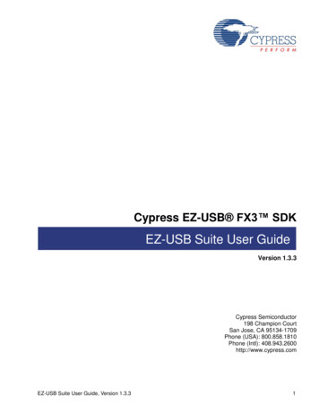
4CX3 Configuration UtilityThis section provides an introduction to MIPI CSI-2 interface on the CX3 deviceand provides a usage guide for the CX3 Configuration tool available as part of theCypress EZ USB Suite Eclipse based IDE. More details on the CX3 part areavailable on the Cypress website at http://www.cypress.com/cx3/4.1Introduction to the CX3 deviceThe CX3 is a variant of the FX3 device that features an integrated MIPI CSI-2receiver mated to the GPIF as shown in the CX3 Logic block diagram. This deviceprovides the ability to add USB 3.0 connectivity to Image Sensors implementing theMIPI CSI-2 interface.LOGIC BLOCK DIAGRAMJTAGMIPICSI2InputMIPICSI-2InterfaceI2C SCLI2C SDAFixedFunctionGPIF SPIUSB InterfaceMemoryControllerARM926EJ-SSSRXSSRX SSTXSSTX DD I2SFigure 4-1: CX3 Device Block DiagramThe MIPI CSI-2 interface on the CX3 supports 1 to 4 CSI-2 data lanes andRAW8/10/12/14, YUV422, and RGB888/666/565 image formats. It reads imageEZ-USB Suite User Guide, Version 1.3.427
data from the sensor, de-packetizes it and sends it in to the parallel interface of thefixed-function GPIF-II interface on the CX3.As the GPIF-II signals on CX3 are connected internally to the MIPI CSI-2 Interfaceblock, it is not possible make use of the GPIF-II to talk to any external devices. Thecontrol signals on the interface are also fixed, and only the width of the data buscan be selected from the values of 8-bit, 16-bit and 24-bits. CX3 firmwareapplications typically make use of a pre-defined GPIF-II configuration with changesbeing made only to the data bus width and the counter limits used.Support for the MIPI CSI-2 interface is provided through a new firmware libraryadded to the SDK (cyu3mipicsi.a). The APIs provided by the library and the datastructures and enumerations used by this interface are provided through thecyu3mipicsi.h header file.4.2CX3 MIPI CSI-2 interface4.2.1Data LanesThe MIPI CSI-2 interface on the CX3 supports 1 to 4 CSI-2 data lanes eachcapable of transfers of up to 1 Gbps. The number of data lanes to be selected for aCX3 application will depend upon the number of data lanes provided by the ImageSensor and the total required data transfer rate.4.2.2MIPI CSI-2 stream formats supported by the CX3The MIPI CSI-2 interface on the CX3 supports the following stream formats andoutput modes:Table 4-1: Stream formats supported by CX3FormatandModeCX3 Enumeration TypeDescriptionCSI-2DataTypeOutput StreamRAW8CY U3P CSI DF RAW8Bayer format 8-bits perpixel data stream.0x2A8-Bit Output: RAW[7:0]RAW10CY U3P CSI DF RAW10Bayer format 10-bits perpixel data stream.0x2B16-Bit Output: 6’b0, RAW[9:0]RAW12CY U3P CSI DF RAW12Bayer format 12-bits perpixel data stream.0x2C16-Bit Output: 4’b0,RAW[11:0]RAW14CY U3P CSI DF RAW14Bayer format 14-bits perpixel data stream.0x2D16-Bit Output: 2'b0,RAW[13:0]RGB888CY U3P CSI DF RGB888RGB 888 format 24- bitsper pixel data stream.0x2424-Bit Output: R[7:0],G[7:0],B[7:0]RGB666Mode 0CY U3P CSI DF RGB666 0RGB 666 format 24- bitsper pixel data stream.0x2324-Bit Output:2’b0,R[5:0],2’b0,G[5:0], 2’b0,B[5:0]EZ-USB Suite User Guide, Version 1.3.428
FormatandModeCX3 Enumeration TypeDescriptionCSI-2DataTypeOutput StreamRGB666Mode 1CY U3P CSI DF RGB666 1RGB 666 format 24- bitsper pixel data stream.0x2324 Bit Output: 6’b0,R[5:0],G[5:0],B[5:0]RGB565Mode 0CY U3P CSI DF RGB565 0RGB 565 format 24- bitsper pixel data stream.0x2224 Bit ’b0RGB565Mode 1CY U3P CSI DF RGB565 1RGB 565 format 24- bitsper pixel data stream.0x2224 Bit Output:3’b0,R[4:0],2’b0,G[5:0], 3’b0,B[4:0]RGB565Mode 2CY U3P CSI DF RGB565 2RGB 565 format 16-bitsper pixel data stream.0x2216 Bit Output: R[4:0],G[5:0], B[4:0]YUV422 8Bit Mode 0CY U3P CSI DF YUV422 8 0YUV422 format 8-bits perpixel data stream.0x1EYUV422 8Bit Mode 1CY U3P CSI DF YUV422 8 1YUV422 format 8-bits perpixel data stream.0x1EYUV422 8Bit Mode 2CY U3P CSI DF YUV422 8 2YUV422 format 8-bits perpixel data stream.0x1EYUV42210-BitCY U3P CSI DF YUV422 10YUV422 format 10-bitsper pixel data stream.0x1F8 Bit Output: P[7:0]Data Order: U1,Y1,V1,Y2,U3,Y3,.16 Bit Output: P[15:0]Data Order:{U1,Y1},{V1,Y2},{U3,Y3},{V3,Y4}.16 Bit Output: P[15:0]Data Order:{Y1,U1},{Y2,V1},{Y3,U3},{Y4,V3}.16 Bit Output: 6'b0,P[9:0]Data Order:U1,Y1,V1,Y2,U3,Y3,V3,Y4.If the GPIF interface used is larger than the width of the output stream (e.g. if a 24bit GPIF II interface is used for the CY U3P CSI DF YUV422 8 1 type) theupper bits on the GPIF II interface will be padded with 0s.4.2.3MIPI CSI-2 interface clocksThe primary clocks on the MIPI CSI-2 interface of the CX3 are shown in Figure 4-2below.The interface takes a reference clock as its input and generates the requiredclocking using a PLL and multiple clock dividers on the PLL generated clock. Clockconfiguration parameters are a part of the CyU3PMipicsiCfg t structure whichpassed to the CyU3PMipicsiSetIntfParams() API to configure the CSI-2 interface.EZ-USB Suite User Guide, Version 1.3.429
CSI RX LP - HS CLK DIVIDER(2 / 4 / 8)REFCLKPLLCSI RX CLKPLL CLKPARALLEL OUTPUT CLOCK(PCLK) DIVIDER(2 / 4 / 8)PCLKFigure 4-2: CX3 MIPI CSI-2 Interface ClocksA brief description of each of the clocks is provided below:1. Reference Clock (REFCLK)This is the input reference clock provide to the MIPI-CSI interface. This input clockshould be between 6 and 40 MHz.2. PLL Clock (PLL CLK)The PLL CLK is the primary clock on the MIPI CSI-2 interface. The minimum legalvalue for PLL clock is 62.5 MHz and maximum legal value for the PLL is 1 GHz.All other internal/output clocks are derived from this clock.The PLL clock frequency is generated from the Input Reference Clock using thefollowing equation:PLL CLK REFCLK * [(pllFbd 1)/(pllPrd 1) ] /(2 pllFRS)wherepllPrd is the input divider whose range is between 0 and 0x0F.pllFbd is the feedback divider whose range is between 0 and 0x1FF.pllFRS is the frequency range selection parameter which takes the followingvalues:0 if PLL Clock is between 500MHz- 1GHz.1 if PLL Clock is between 250MHz- 500MHz.2 if PLL Clock is between 125MHz- 250MHz.3 if PLL Clock is between 62.5MHz- 125MHz.EZ-USB Suite User Guide, Version 1.3.430
E.g.:If RefClk is 19.2 MHz, pllFbd is 69, pllPrd is 1, and PLL Clock range is in the500MHz-1GHz range (i.e. pllFrs 0),PLL Clock (MHz) 19.2 * [(69 1)/(1 1)]/(2 0) 19.2 * [70/2]/1 672 MHzFor the same values, changing PLL frequency range to 125-250MHz (pllFrs 2)will change the PLL Clock value toPLL Clock (MHz) 19.2 * [(69 1)/(1 1)]/(2 2) 19.2 * [70/2]/4 168 MHz3. CSI RX LP HS Transition ClockThis clock is used for detecting the CSI link LP - HS transition. It is generated bydividing the PLL Clock by a value of 2, 4 or 8.The minimum value for this clock is 10Mhz and maximum value for this clock is125MHz.4. Output Parallel Clock (PCLK)This clock is the PCLK output which drives the fixed-function GPIF interface on theCX3. It is generated by dividing the PLL Clock by a value of 2, 4 or 8.The maximum value for this clock is 100MHz.4.3Configuring the CX3 DeviceThe typical CX3 application is a USB Video Class (UVC) compliant Cameraapplication that streams video or still image data captured by an Image Sensor to ahost PC. Most parts of a CX3 system design are common, with the only variationsbeing in the Image Sensor and data formats chosen.The typical steps involved in UVC implementations using the CX3 device are:1. Configuring the image sensor as required.2. Configuring the MIPI CSI-2 interface on the CX3 device based on the imagesensor settings.3. Defining the USB descriptors for the application based on the image formatsto be supported.4. Implementing the actual image streaming logic using CX3/FX3 APIs.5. Implementing the sensor control operations required to handle requests onthe Video Control interface (e.g. brightness, pan – tilt – zoom etc.)EZ-USB Suite User Guide, Version 1.3.431
The EZ-USB Suite application provides a CX3 Configuration utility that helps insteps 2, 3 and 4. The actual image sensor control (step 1) and the control interfacehandling (step 5) are sensor dependent, and not handled by the tool.4.3.1MIPI CSI-2 ConfigurationThe MIPI CSI-2 interface on CX3 is configured using theCyU3PMipicsiSetIntfParams() API. This API takes an input parameter of typeCyU3PMipicsiCfg t which contains various configurations like output data format,clock dividers and configuration parameters, number of CSI data lanes to use,horizontal resolution etc.The CSI Configuration Utility generates the data required to configure the interfacein the form of C code which can be embedded into the firmware application.4.3.2Defining the USB DescriptorsThe UVC specification defines the format for the USB configuration descriptors forall UVC compliant devices. The size of the configuration descriptor can stretch to200 bytes or more depending on the number and types of video formats andresolutions supported. Putting together the descriptors in a fully spec compliantmanner across all three USB connection speeds (SuperSpeed, Hi-Speed and FullSpeed) is a cumbersome process.The CSI Configuration Utility generates the USB descriptors based on the settingsprovided. The descriptor data is generated in the form of C code which can beembedded into the firmware application.4.3.3Video Streaming LogicThe firmware design and implementation to handle video streaming includeselements such as:1. Defining the buffering requirements for the video stream.2. Setting up the DMA connection from the GPIF-II interface to the USBendpoint3. Handling Video Streaming control requests to negotiate the video format andresolution.4. Managing the actual video data transfer with UVC header addition.The CSI configuration tool generates C header and source files that implement thislogic. These files can be used along with the CSI-2 configuration file and the USBdescriptor file to create the UVC firmware project.The next section describes the usage of the MIPI CSI-2 Configuration tool providedas part of the EZ-USB Suite IDE.EZ-USB Suite User Guide, Version 1.3.432
4.4Using the CSI Configuration Utility4.4.1Creating a new CX3 Configuration ProjectFrom the File menu of the EZ USB Suite IDE, select the New Other option.Figure 4-3: CX3 Configuration File Creation MenuFigure 4-4: CX3 Configuration Project Creator4.4.2Image Sensor Selection and ConfigurationThe first step in configuring the CX3 UVC project is to define the properties of theimage sensor being used in the system. This includes properties like the type ofsensor, still image and video capture support, the format and resolution of theimages etc.Configurations for the Aptina AS0260 and OmniVision OV5640 sensors areprovided as part of the tool, and you can use these directly if these sensors arebeing used. If other sensors are being used, the wizard can be used to input thesensor properties for conversion into the required format.EZ-USB Suite User Guide, Version 1.3.433
4.4.2.1 CX3 Configuration Project CreationThe CX3 Configuration Project Creation Wizard provides three possiblealternatives for configuring the newly created project:1. Create a Configuration with Basic Settings2. Select a Pre-Defined Configuration3. Select an User defined ConfigurationThe steps for configuring the MIPI CSI-2 interface and image sensor using each ofthe three possible options are described in the following sub-sections.4.4.2.1.1 Configuration with Basic Settings1. Click on Create a Configuration with Basic Settings Radio Button andprovide a new name to the project. Click on Finish button to start generatingrelevant configuration data.Figure 4-5: CX3 Configuration Project SelectorEZ-USB Suite User Guide, Version 1.3.434
2. An empty Image Sensor Configuration window with no pre-defined sensorand frame opens up. A new CX3 Project is created under the Eclipse workspaceas well.Figure 4-6: Image Sensor Configuration Stage3. Input the desired sensor configuration and select the appropriate video formatfrom the dropdown list provided in the configuration window.a. A name string can be provided for the sensor.b. The THS-Prepare value represents the duration for which the sensordrives the CSI data lane LP-00 line state before starting the HStransmission. This value can be determined from the image sensordatasheet.c. The THS-Zero value represents the duration for which the sensordrives the HS-0 state before transmitting the sync sequence. Thisvalue can also be determined from the image sensor datasheet.d. The Input Video Format represents the video picture encoding formatsupported by the sensor. This has to be selected from the drop-downlist.e. The Output Video Format represents the data size of each pixel in theimage stream. This has to be selected from the drop-down list.Figure 4-7: Image Sensor ConfigurationEZ-USB Suite User Guide, Version 1.3.435
4. Each Image Sensor may be capable of supporting multiple video resolutionsand frame rates. The Frame Configuration area of the Image Sensorconfiguration wizard can be used to input the supported (desired) frameresolutions and frame rates. The properties to be specified for each frameconfiguration includes:a. A name string to identify the configuration.b. The number of CSI-2 data lanes used.c. The CSI-2 clock frequency used.d. The H-Active value represents the frame width in number of pixels.e. The H-Blanking value represents the horizontal blanking period aftereach line of image data is transferred.f. The V-Active
2 Creating an FX3 Firmware Project This chapter outlines the steps involved in creating a FX3 firmware application, using the GpifToUsb project from the SDK as a reference. 2.1 Starting the EZ-USB Suite IDE Launch the EZ-USB Suite IDE by following the "All Programs - Cypress - Eclipse - EZ USB Suite" path from the Start Menu.