Transcription
ApplicationEngineeringApplicationEngineeringBL LL E L T EIBU UNTINAE8-1368 R1April 2012AE8-1368 R1CoreSense Diagnostics v2.11 for Copeland Discus CompressorsTable of Contents1.0 94.201.1 Functionality1.1.1 Diagnostics1.1.2 Communication1.1.3 Fault History1.2 Features1.2.1 Compressor Protection1.2.2 Remote Reset1.2.3 Failsafe Operation1.2.4 Welded Contactor Protection1.2.5 Crank Case Heater Control1.2.6 Start-up Delay Feature1.2.7 “Jog” feature1.2.8 Dipswitch Settings5.0 Stand Alone Installation & Operation6.0 Compressor Status Codes & Troubleshooting1.3 Modulation Control1.4 Application Restrictions6.16.22.0 Installation Instructions2.1 Mounting and Installation2.2 Terminal Box Connections2.2.1 Current Sensing Module2.2.2 Fan Connections2.3 Controller Requirements2.4 Communications Network2.5 Network Terminations and Cable Routing2.5.1 RS485 Wiring Types2.6 CoreSense Diagnostics v2.11 ServiceInstructions2.7 Compatibility of Service Compressors2.8 CoreSense Diagnostics v2.11 Model Numbers3.0 Quick Start Guide4.0 Commissioning Procedure4.14.24.34.44.54.64.74.8Dip Switch Con¿gurationNetwork SetupEnhanced Suction Group SetupAssociationsProo¿ngFailsafeCoreSense Diagnostics v2.11 Setup ScreensUnloader Con¿guration 2012 Emerson Climate Technologies, Inc.Printed in the U.S.A.Demand Cooling Con¿gurationCrankcase Heater ControlAnti Short CycleMCC ValueCompressor VoltageCompressor FrequencyLanguageVoltage BalanceInputsOutputsID Con¿gurationCoreSense Diagnostics v2.11 nitionsEvent Priority and Troubleshooting6.2.1 Event Priority & Anti Short Cycle Delay6.2.2 LED InterpretationEvent Priority TableEmergency Work-Around ProceduresNormal RunningNormal OffWelded Contactor WarningModule Low Voltage TripConnection Lost CT to SensorRack Controller LockoutFault Temperature ProbeFail-Safe InoperableLocked Rotor Trip / LockoutNo CommunicationMotor Temperature TripNo Communication to Sensor ModuleUnloader ShortUnloader OpenContactor Coil LockoutProtector TripVoltage Imbalance TripLow Suction Pressure TripPhase Loss Trip / LockoutNo 3-Phase PowerLow Oil Pressure Warning / Lockout
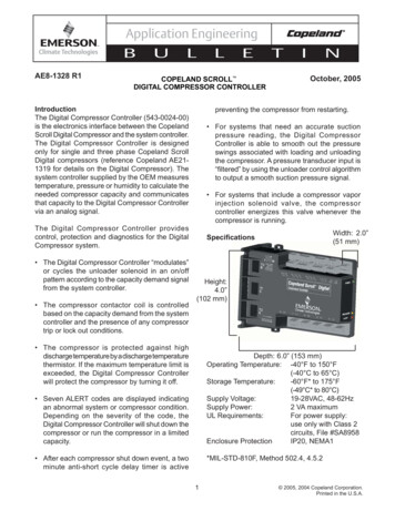
Application EngineeringBULL6.266.276.286.296.306.31Control Module Failure LockoutSensor Module FailureHigh Discharge Pressure TripDischarge Temperature LockoutCurrent Overload TripRapid Compressor Cycling with ConstantDemand6.32 Discharge Temperature Probe Fault Trip6.33 Comp Low Voltage Trip/Lockout7.0 Service Instructions7.17.27.37.47.57.67.7ETINAE8-1368 R18.0 Compressor Changeout Instructions9.0 Removal Of 2D / 3D10.0 Installation Of 2D / 3D11.0 Removal Of 4D12.0 Installation Of 4D13.0 Removal Of 6D14.0 Installation Of 6DAppendixA.B.C.D.E.F.G.Control Module ReplacementSensor Module ReplacementInstallation Torque ValuesDemand Cooling Service ProceduresTemperature Probe InspectionCoil Inspection and ReplacementInjection Valve ReplacementTerminal Box DiagramHarness Wiring DiagramTransformer Selection and Contactor ControlDielectric Test (Hi-Pot)Compressor DrawingsTechnical Support InformationService Parts List1.0 Overview of the Copeland Discus Compressorwith CoreSense Diagnostics v2.11CoreSense Diagnostics v2.11 is now available on 2D,3D, 4D and 6D compressors and integrates a numberof important sensing and compressor protectionfunctions. This product provides for on/off control of thecompressor, capacity modulation (both conventionalblocked suction and with Copeland Discus Digital capacity modulation) and for communication of thecompressor status to the rack controller througha network using MODBUS for Intelligent Storecommunication protocol. Protection against low oilpressure, excessive discharge temperature, highdischarge pressure and low suction pressure isstandard on every Copeland Discus compressorwith CoreSense Diagnostics. A 2-line liquid crystaldisplay on the front of the compressor indicates theoperational status of the compressor with a choiceof 5 languages. An LED on the compressor controlmodule indicates at a glance whether or not there areany compressor faults.The “2.11 version” of this product provides the samebasic protection and feature package as the previous“1.0” product, but with enhancements such as additionalmotor protection, accessory proo¿ng and modulationcontrol and demand cooling control.Note: Throughout this manual the term “ControlModule” refers to the electronic control box on thefront of the compressor which contains the display andreset buttons. The “Sensor Module” is located insidethe terminal box. 2012 Emerson Climate Technologies, Inc.Printed in the U.S.A.2Figure 1.11.1 Functionality1.1.1 DiagnosticsThe status of the Copeland Discus compressor withCoreSense Diagnostics may be viewed at any time onthe LCD display by pushing the Display button on thefront of the control module. Normal conditions will beaccompanied by a steady green LED (light emittingdiode) on the front of the control module.If a fault occurs that doesn’t interfere with the abilityof the compressor to run, the LED will transition to aÀashing green. The display will provide a description ofthe fault. This is referred to as a warning.A trip or lockout condition will result in a Àashing redLED. This is an indication of a condition that is keepingthe compressor from running.
Application EngineeringBULLAs with all conditions, the status of the compressor andthe display code are transmitted to the rack controllerwhere they may be viewed.The status codes are discussed below in Section 6.0.Troubleshooting Àowcharts to assist with resolution ofeach of the warnings, trips and lockouts may also befound in Section 6.0.1.1.2 CommunicationsCommunication between the rack controller and eachCoreSense Diagnostics module is through an RS485network with MODBUS. The two-wire communicationcable is daisy-chained from one compressor to thenext on each rack.Compressor operations such as on/off control,modulation operation, transmission of compressorstatus and run proo¿ng are all accomplished throughthe communication network. Password protectedremote reset of certain compressor lockouts may alsobe done through the communication network if thisfunctionality has been enabled through the controller.Capacity modulation functions are discussed in detailin Section 1.3, and in Commissioning / Suction GroupSetup Section 4.3.The Emerson Retail Solutions’ controller E2, version2.6 or higher, may be con¿gured to send alarmsfor different levels of compressor faults, such as forwarnings, trips and lockouts.The Failsafe mode may be con¿gured to turn thecompressor on or off in the event of a communicationsfailure. This con¿guration is accomplished via adipswitch setting inside the lower cover of the controlmodule.1.1.3 Fault HistoryThe 10 most recent warnings, trips or lockouts maybe observed through the E2 alarm history screen. An8 –day log of each fault is also available as well as anaccumulated record for the history of the compressor.Graphing features available with the E2 controllerprovide a powerful diagnostics tool to help understandthe source of system or compressor faults. Dateand time stamping of faults and alarms can help toassociate the fault with system events (such as defrostcycles).Like previous versions of Intelligent Store Discus, theCoreSense Diagnostics module will store the faulthistory record. 2012 Emerson Climate Technologies, Inc.Printed in the U.S.A.3ETINAE8-1368 R11.2 Features1.2.1 Compressor ProtectionCompressor protection may be in the form of a TRIP,where the compressor will be shut off until the faultcondition no longer exists (and in some cases aminimum off-time is satis¿ed), or a LOCKOUT. ALOCKOUT is a condition whereby the compressor willremain off until the fault condition no longer exists ANDthe manual reset button is pushed (or power to thecontrol module is cycled). Lockouts may also be resetfrom the E2 or remotely through Site Manager, includingoil pressure if remote re-set has been enabled for thisfault (this is password protected). A WARNING is afault that doesn’t keep the compressor from running(an example is an open or shorted unloader coil).The following compressor protection features areprovided on all Copeland Discus compressors withCoreSense Diagnostics: High discharge pressureLow suction pressureDischarge temperatureLine-break motor protection (2D / 3D)Motor temperature protection (CoreSenseDiagnostics replaces the solid-state module usedon 4D / 6D compressors)Low voltagePower interrupt motor protectionWelded contactor protectionLoss of phase motor protectionLow oil pressure (CoreSense Diagnosticsreplaces the Copeland brand Sentronic oilpressure protection modules).Part winding start failureLocked rotor and settable MCC protectionShorted unloader coil protectionShorted contactor or pilot relay coil protectionThe following options are available with CopelandDiscus compressors with CoreSense Diagnostics: Crank case heater control Blocked suction modulation (4D/6D compressors) Discus Digital capacity modulation (3D/4D/ 6D)Note: The conventional blocked suction orModuload valving MAY NOT be activatedto perform in a digital fashion. These valvemechanisms have not been designed towork reliably in a digital fashion. Only usethis feature with Discus Digital modulationhardware.
Application EngineeringBULL1.2.2 Remote ResetThe oil pressure lockout may be reset through the E2or remotely through Site Manager if the reset option isenabled.ETINAE8-1368 R1This is not to be confused with single-phase protectionat start-up or while running. In that case, the contactorwill be instructed to “open”, shutting down thecompressor.The service contractor and end user policies needto be considered when deciding whether to enableor disable the oil pressure remote reset feature. Thedefault condition is to “disable” this feature.1.2.5 Crank Case Heater (CCH) ControlRefer to Section 4, Figure 4.15 for enabling ordisabling this remote reset.The appropriate voltage supply to the CCH power inputterminals (115 V / 230 V) is required.1.2.3 Failsafe Operation1.2.6 Start-up Delay FeatureThe FAILSAFE mode may be con¿gured at any timeby setting the #10 dipswitch to the “on” or “off” positionas desired. The failsafe condition is acted upon by thecompressor in the event that communication is lostfor 5 or more minutes. Upon the re-establishment ofcommunication to the rack controller the run commandfrom the rack controller overrides the failsafe command.To reduce the sudden in-rush of power associatedwith multiple compressors starting at one time,compressor start-ups are staggered slightly at the endof the anti-short cycle delay. The delay is equal to 100milliseconds x node number. Therefore node number4 will start 0.3 seconds after node number 1. Refer tothe status code table to see which events trigger ananti-short cycle delay.The failsafe switch position may be changed at anytime.However, the module must be reset before the controlmodule recognizes a change in the switch position.When the compressor is running in the failsafe “on”position, all of the compressor protection features areenabled with the exception of welded contactor.There are different philosophies regarding the failsafesettings. One suggestion is to observe the typical“percent of full load capacity” required to satisfydemand (this is perhaps seasonal). Setting theswitches to provide this capacity (with perhaps a littlereserve) is one approach.As with all dipswitch positions, a legend may be foundinside the lower cover of the control module thatexplains the switch positions.1.2.4 Welded Contactor ProtectionVoltage is sensed at the motor terminals of theCopeland Discus compressor with CoreSenseDiagnostics. If voltage is present after the contactorhas been signaled to “open”, the module will send awelded contactor alarm to the E2. The E2 then issuesa run command to the module to load the contactor,bringing all three legs of the power supply to thecompressor back on line. This prevents a single-phasemotor burn. The compressor will run continuously untilthe unit is manually shut down or the alarm is clearedin the E2. Safety devices (pressure switches and motorprotection) will attempt to override this feature. 2012 Emerson Climate Technologies, Inc.Printed in the U.S.A.4The sensor module contains an on-board CCH controlrelay. An auxiliary contactor is no longer required toturn the heater on when the compressor turns off.1.2.7 “Jog” FeatureThe reset button on the front of the control modulemay be used as an emergency shutdown, such asfor clearing liquid during a start-up. After the modulere-boots (approximately 30 seconds) the compressorwill run again. The reset button may be pushed asnecessary to stop the compressor.1.2.8 Dipswitch SettingsDipswitch selection for the address, baud rate, parity,operating and failsafe mode selection simplify serviceand start-up procedures. At initial power-up or afterpushing the Reset button, the following information willbe displayed on the LCD:Control Module Firmware VersionSensor Module Firmware VersionNode AddressBaud Rate(9600 or 19200)Parity(Parity or No Parity)Mode(Network or Stand-Alone)Failsafe(ON or OFF)1.3 Modulation ControlCoreSense Diagnostics v2.11 can control blockedsuction (conventional unloading) valves or Digitalunloading valves without separate relay outputs orthe need for an IDCM module. Demand from the rackcontroller to the unloader valve is through the RS 485communication network and the actual on/off control isfacilitated by the control module.
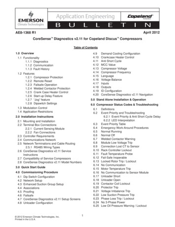
Application EngineeringBULLDigital modulation will be available for the 3D, 4D and6D compressor. The E2 can control any combinationof compressors, blocked suction compressors and/or digital compressors. When more than one digitalcompressor is in a suction group, only one compressorat any given time will be operating in a “digital” mode(i.e. modulating in a pulse-width fashion).Blocked suction (and Moduload) compressors are setup in the suction group as stages (i.e. the compressoris one stage and each unloader is one stage). The totaloutput of the compressor (horsepower or capacity)is the sum output of each individual stage. Whenan unloader stage is “on” it is producing capacity(this is when the solenoid is de-activated, or “off”). Ifyou override an unloader stage “off”, the solenoid isenergized.When setting up the suction group using Digitalcompressors, the compressor is one stage (regardlessof the number of unloaders). A 3D Digital, 4D Digital,6D Digital with one unloader or a 6D Digital with 2unloaders are all con¿gured as one stage.The digital control cycle is by default a 20 secondperiod. Within this period the output of the compressorwill be pulsed to produce (on average) the capacityrequested by the controller. The advantages of Digitalcontrol are signi¿cant: Dramatically reduced compressor contactorcyclingETINAE8-1368 R1For proper Demand Cooling control, the following¿rmware versions are required: control module 1.30F05 or later, sensor module - 2.00F03 or later.Low Temperature Operation – The CoreSenseDiagnostics electronics are designed to operatebetween -25 F and 150 F. At temperatures below 0 Fthe LCD display may be “slow”, but the compressorstatus information in the E2 is up-to-date.2.0 Installation InstructionsEmerson Climate Technologies requires that allcustomers review the recommended guidelines inthe published Application Engineering Bulletins, andensure that best engineering practices are followedin the use of Copeland compressors. EmersonApplication Engineering Bulletins can be found on ourwebsite, www.EmersonClimate.com under the sectiontitled “Online Product Information." The advice andconclusion by Emerson represents our best judgmentunder the circumstances, but such advice given and/orconclusion made, or results obtained shall be deemedused at your sole risk.Modulation Control - CoreSense Diagnostics v2.11RS 485Communication Tighter control of pressure or temperature Reduced set-point errorRefer to Figure 1.2 for a comparison between themodulation control requirements with and withoutCoreSense Diagnostics v2.11. The conventionalcontrol arrangement that is depicted shows acompressor without modulation, a compressor withconventional blocked suction modulation and one withDigital modulation.Modulation Control w/o CoreSense Diagnostics1.4 Application RestrictionsVariable Speed – CoreSense Diagnostics v2.11 is notapproved for use with variable speed drives. Otherdevices on the rack may use variable speed, butthe compressor itself may not be modulated with aninverter.Demand Cooling – The Copeland Discus compressorwith CoreSense Diagnostics is equipped with DemandCooling capability, and as such may be used as anR407A / R407C low temperature compressor. 2012 Emerson Climate Technologies, Inc.Printed in the U.S.A.5IDCM ModuleFigure 1.2 – Modulation Control
Application EngineeringBULL2.1 Mounting and InstallationThe Copeland Discus compressor with CoreSenseDiagnostics is designed and engineered for use ina supermarket rack application. Its environmentalrestrictions are not different than other CopelandDiscus compressors. As such, the compressor mustbe in an equipment room, rack house or roof enclosureto prevent direct precipitation on the compressor. Thefollowing clearance provisions must be consideredwhen designing the rack for use with a Copeland Discuscompressor with CoreSense Diagnostics: Removal of the lower cover of the control modulefor access to dip-switches and the communicationnetwork connector Removal of the control module for servicereasons Removal of the pressure switch cover (2D / 3D)for service reasons Removal of the harness cover shroud (4D / 6D) Removal of terminal box lids for service reasonsETINAE8-1368 R1auxiliary contact on the contactor is not required.Use AMP terminals (2x) 520194-2 Copeland Discus compressor with CoreSenseDiagnostics use the same motor terminalconnections.While the Copeland Discus compressor withCoreSense Diagnostics is primarily intended for use insupermarket rack applications, it is possible to utilizethis technology in other applications without acommunication network. Con¿guring the dipswitchsettings to the “stand alone” position allows thecompressor and unloaders to be controlled by a 24 voltsignal to input leads in the terminal box. Protection,control and diagnostic features are still functioningwhile in the stand-alone control mode.Refer to customer drawings in Appendix F fordimensional envelopes of CoreSense Diagnostics.Inherent in the functionality of the control moduleis short-circuit protection for the following circuits:Unloader coil operation and contactor output.Additional electrical requirements and speci¿cations(such as transformer selection) are provided inAppendix C.2.2 Terminal Box ConnectionsRefer to Figure 2.1 for terminal box connectionlocations.FeatureElectrical RequirementsCoreSense DiagnosticsSupply Voltage(Module Power)24 volts ACClass II power supplyPilot Circuit Voltage(Contactor Output)24 volts AC(supplied by CoreSenseDiagnostics v2.11 to the pilotrelay, or contactor)Crank Case Heatervoltage supply115/208/230 per customerspeci¿cationCompressor MotorModel DependentHead FanPer OEM Wiring2.2.1 Current Sensing ModuleAll Copeland Discus compressors with CoreSenseDiagnostics use a current sensing module in theterminal box. One of the motor power leads passesthrough the “toroid” (current sensor). Information fromthe current sensor is used to determine running amps,power consumption and locked rotor conditions.The following terminal box connections must be madeby the original equipment manufacturer: Module power – 24 volts AC supplied by a ClassII power supply. This powers the electronics,unloaders, crank case heater relay, and contactoroutput (to load the pilot relay or contactor). UseAMP terminals (2x) 520184-2 Contactor – Output connections to the contactorpilot relay or contactor coil. Use AMP terminals(2x) 520183-2 or 520184-2 Crank case heater power supply – 115vac or208/230vac. A switching relay inside the sensormodule controls the crank case heater. An 2012 Emerson Climate Technologies, Inc.Printed in the U.S.A.6There are 3 voltage sensing leads attached to the motorterminals and connected to the sensor module. Twoof the leads are white, and one is black. For propercalculation of power factor and motor power it isnecessary for the black voltage sensing lead andthe power lead through the current sensor to beconnected to the same motor terminal.Motor Power24v AC Class IIPower SupplyCrank CaseHeater PowerContactor Output toControl ContactorFigure 2.1 – Terminal Box Connections
Application EngineeringBULLERefer to Figure 2.2 for sensor module lead connections.TINAE8-1368 R1regarding the CoreSense Diagnostics compatible rackcontroller.2.2.2 Fan Connections2.4 Communications Network Copeland Discus compressors with CoreSenseDiagnostics are not shipped from the factory withfans installed. OEM installation of fans shouldfollow established regulatory, OEM engineeringand end user speci¿cations regarding wiring.The CoreSense Diagnostics module and rackcontroller communicate with each other usingMODBUS communications protocol. The wiringnetwork uses RS485 hardware connections at eachnode. The CoreSense Diagnostics communicationcable terminates in the rack controller at an interfacecard and is routed to each compressor in a daisy-chainformat. Refer to Figures 2.5, 2.6 and 2.7. Head fan requirements for these compressorsare identical to other Discus compressors. Referto Application Engineering Bulletin AE4-1135.2.3 Controller RequirementsOne E2 controller can control two racks. One daisychain may be used for 2 racks, but two RS-485connections are available on the Network InterfaceBoard if two parallel daisy-chains are preferred. TheCoreSense Diagnostics Network Interface Board isshown on Figure 2.6The control network utilizes an open MODBUSprotocol. Rack controller manufacturers may developequipment to interface with and control CopelandDiscus compressors with CoreSense Diagnostics.For Non-Emerson Retail Solutions products, consultwith the controller manufacturer regarding controllercompatibility with CoreSense Diagnostics v2.11.One E2 controller can control 4 suction groups, with upto 16 stages in each suction group.For the Emerson Retail Solutions E2 controller, itmust be equipped with an Emerson Retail SolutionsCoreSense Diagnostics Network Interface Board(Emerson Retail Solutions part number 637-4890).The controller ¿rmware must be revision level2.60F01 or higher.2.5 Network Terminations and Cable RoutingEach compressor (network node) has a jumper thatmust be positioned to de¿ne whether or not the nodeis in the middle or end of the daisy-chain. The lastcompressor in the daisy-chain is “terminated” andthe jumpers must be set accordingly. The E2 jumperson the Network Interface Board are always set forRefer to Emerson Retail Solutions E2 RX RefrigerationController manual 026-1610 for detailed informationSensor Module ConnectionsInput VACToContactoror PilotRelay24 VAC Class II OutputBlackCCH(From harness in terminal box)WhiteTerminal Plateor FusiteCrank Case HeaterPower Supply(115 or 230 VAC)CONTROLCCHMODULEPOWER E SENSING LEADL3SENSOR MODULEL2L3CURRENT SENSING L1POWER LEADImportant! Black Voltage SensingLead Connected to SameTerminal as Current SensorPower LeadCTL1 2012 Emerson Climate Technologies, Inc.Printed in the U.S.A.Figure 2.2Sensor Module Wiring7
Application EngineeringBULLETINAE8-1368 R1“terminated” (refer to Figure 2.6).2.5.1 RS485 Communication Wiring TypesThe communications wire to the compressor may berouted into the rear of the side conduit (2D / 3D) andalong the channel which leads into the control module.The 4D and 6D wire routing can be alongside the wireharness and into the control module.A shielded, twisted pair cable such as Belden #8761(22AWG) should be used for the communication wiring.Appropriate use of strain reliefs will prevent damage tothe circuit board connector in the event of an accidentalmechanical load to the communication wire. Note thatthe rear of the 2D / 3D conduit contains a tie-wrapfeature for anchoring the communication wire. Refer toFigure 2.9 for photos of wire routing.Important ! Note that the RS485 is polarity sensitive.“Pos” wires must connect to other “Pos” terminals, and“Neg” wires must connect to other “Neg” terminals.The shield wire is connected to the center terminal,or “0 volt” position. Refer to Section 6.15 for voltagespeci¿cations and troubleshooting.Figure 2.5RS-485 Daisy-ChainCon¿guration2.6 CoreSense Diagnostics v2.11 ServiceInstructionsRefer to Sections 3, 4, 6 and 7 of this documentfor commissioning, service and troubleshootinginstructions.2.7 Compatibility of Service CompressorsThe following S/Ns may be used to determine whetherservice compressors are compatible with CoreSenseDiagnostics hardware and accessories:2D built on or afterS/N 04D3D built on or afterS/N 04D4D built on or afterS/N 05D6D built on or afterS/N 05DFigure 2.6CoreSense Diagnostics Network Interface BoardFigure 2.92D / 3D Communication Wire RoutingFigure 2.8Communication Wiring and Jumper Positions 2012 Emerson Climate Technologies, Inc.Printed in the U.S.A.Figure 2.7Two Rack Daisy-Chain8
Application EngineeringBULL2.8 CoreSense Diagnostics v2.11 Model NumbersFactory built Discus compressors with an S/E (thelast 3 digits in the model number) beginning with “A”are Copeland Discus compressors with CoreSenseDiagnostics. Models with an S/E that begins with "AD"are equipped with Demand Cooling. The remainingnumbers de¿ne the service valve con¿guration as wellas crankcase heater presence.3.0 CoreSense Diagnostics v2.11 Quick Start Guide1) Module PowerApply power to the CoreSense Diagnostics v2.11sensor modules located in the compressor terminalbox. Power requirements for the CoreSenseDiagnostics v2.11 modules is a 24VAC supplyprovided by a class II transformer. For additionalinformation on transformer selection includingVA requirements refer to Appendix C of thisdocument.2) Communication WiringConnect the CoreSense Diagnostics v2.11 controlmodules to the rack controller by con¿guringthe RS-485 communications network. Thecommunication cable terminates in the rackcontroller on the Network Interface Board, and isrouted to each of the compressors in a daisy-chainformat. For communications to function properlythe termination jumpers at the rack controller andeach module should be set according to theirposition in the chain. The end devices (includingthe rack controller) should be set to the terminatedposition. The devices in the middle of the chainshould be set to unterminated. The CoreSenseDiagnostics v2.11 control modules have theability to communicate to E2 or non-E2 rackETI9AE8-1368 R1controllers. Set the controller jumper accordingly.Refer to Figure 3.0 below to locate the positionof the termination and controller jumpers on eachcontrol module. For a complete description of thecommunications network refer to Section 2.4.For details on troubleshooting problems with thecommunications network refer to Section 6.15.3) Verify DIP-Switch SettingsCoreSense Diagnostics v2.11 devices are equippedwith a DIP switch to set the node address. Inaddition, this DIP switch determines the baud rate,parity, control mode, and failsafe settings of themodule. Refer to Figure 3.0 below for details:4.0 CoreSense Diagnostics v2.11 CommissioningProcedureAs with other devices, the CoreSense Diagnosticsv2.11 modules must ¿rst be commissioned to establishcommunications with the rack controller. During thecommissioning process the E2 will recognize theCoreSense Diagnostics v2.11 modules in order asdesignated by the node address settings on themodule DIP switches.Important Note: The following commissioninginstructions pertain to E2 controllers with version3.02F01 or later ¿rmware. If you have an earlierversion of ¿rmware we recommend that you upgradeto the latest version available.To determine the ¿rmware revision level in the E2follow these steps:1. From the main menu select 7 (SystemCon¿guration)2. Press 3 (System Information)3. Press 4 (Firmware Revision)Figure 3.0 – Control Module Instruction Label 2012 Emerson Climate Technologies, Inc.Printed in the U.S.A.N
Application EngineeringBULLThe E2 should look like Figure 4.1.4.1 Dip Switch Con¿gurationCoreSense Diagnostics v2.11 devices are equippedwith a DIP switch to set their node address. In addition,this DIP switch determines the baud rate, parity, controlmode, and failsafe settings of the module. Refer toFigure 4.2 below for details:To ensure proper communications, follow these steps:1. Each CoreSense Diagnostics device that isconnected to a rack controller should have aunique node address (as determined by the DIPswitch settings).2. The communications jumper should be set forE2 communication if connected to an E2 rackcontroller.3. The last CoreSense Diagnostics device in theETINAE8-1368 R1daisy-chain should have the communicationjumper in the “terminated” position. In addition,the E2 should have the communication jumpersin the “terminated” position.4. The parity for each of the CoreSense Diagnosticsdevices should be set to none. This can beaccomplished by setting DIP switch number 8 tothe down position.5. The baud rate for each of the CoreSenseDiagnostics devices should be set according tothe rack controller. To determine the baud rate inthe E2, follow these steps:a. From the main menu select 7 (SystemCon¿guration)b. Press 3 (System Information)c.Press 1 (General Controller Info)d. Access the Serial Communications Tab bypressing CTRL 3e. Use the Page Down button or scroll down toview the MODBUS communication settings.Note: The default location for CoreSensediagnostic modules is the COM4 port, butthere may be multiple MODBUS networksrunning on on
compressor, capacity modulation (both conventional blocked suction and with Copeland Discus Digital capacity modulation) and for communication of the compressor status to the rack controller through a network using MODBUS for Intelligent Store communication protocol. Protection against low oil pressure, excessive discharge temperature, high