Transcription
The Generalized Holographic StereogrambyMichael W. HalleS.B., Computer ScienceMassachusetts Institute of TechnologyCambridge, Massachusetts1988Submitted to the Media Arts and Sciences Section,School of Architecture and Planningin partial fulfillment of the requirementsfor the degree ofMaster of Science in Visual Studiesat theMassachusetts Institute of TechnologyFebruary 1991c 1991 Massachusetts Institute of TechnologyAll Rights ReservedSignature of AuthorMichael W. HalleMedia Arts and Sciences SectionJanuary 18, 1991Certified byStephen A. BentonProfessor of Media TechnologyThesis SupervisorAccepted byStephen A. BentonChairmanDepartmental Committee on Graduate StudentsDocument last updated February 24, 1993.
2
The Generalized Holographic StereogrambyMichael W. HalleSubmitted to the Media Arts and Sciences Section,School of Architecture and Planning, on January 18, 1991in partial fulfillment of the requirements of the degree ofMaster of Science in Visual Studies at theMassachusetts Institute of TechnologyAbstractA general model for holographic stereograms in the context of discrete and continuousoptical systems is presented. Building from a simple, highly constrained model, restrictions on the viewer’s horizontal position and depth, the size and location of the plane of thestereogram’s slits, the spatial resolution of the points in the imaged object, and the opticalproperties of the projection screen are relaxed one by one. Emphasis is placed on accuratemodeling of the stereogram and on the correspondence between the photographic capture,holographic recording, and final viewing geometries. Bandlimiting and anamorphic distortion techniques useful for producing artifact-free images are presented. Discussion centerson horizontal parallax only, flat format, computer generated stereograms, but general conclusions applicable to other stereogram types are drawn. Specific examples of stereogramscreated using these techniques are shown and discussed.Thesis Supervisor: Stephen A. BentonTitle: Professor of Media TechnologyThis research was supported in part by the Defense Advanced Research Projects Agency under Rome AirDevelopment Center (RADC) Contract F30602-89-C-0022, and by the Design Staff of the General MotorsCorporation.
4
DedicationThis thesis is dedicated to my parents. To my mother, whotirelessly strived to challenge her children, and to instill in themthe desire to challenge themselves. And to my father, who neverstopped trying to give us the opportunities that he never had.May this work and all that I do stand as a proud but humbletribute to their ideals and selflessness.5
6
AcknowledgementsAnd now, a word of thanks.Thanks to my cohorts in the Spatial Imaging Group, who were always around to letme banter about some sort of malformed idea, and who looked over drafts of this work.Especially noteworthy: John Underkoffler implemented much of the “weird renderingthings” necessary to apply this paper’s concepts to the images presented. Michael Klugwas the “other half”, doing the lab work without which all this stuff would be academic.He also provided several of the photographs used in this text. Both put up with a lot of falsestarts and provided extended comic relief through late nights and Thanksgivings.Thanks to Stephen Benton, my advisor, for making available the fine facilities of theSpatial Imaging Group, and for his review of this lengthy document.And thanks to my housemate Steve Pieper, whose timely acquisition of a PersonalIris created an unparalleled thesis production environment without which this documentwould not have been possible.7
8
Contents1Introduction112Stereogram Basics153Bandlimiting454Separating the Slits from the Viewer675Practical Examples996Conclusion and Future Work117A Glossary of Terms121B Two Extended Examples1279
10
Chapter 1IntroductionEver since the first stereo photographs were produced in the 1800’s, humanity has beenfascinated with the idea of a medium capable of accurately recording and displaying a scenein three dimensions. Many schemes for three-dimensional display have been created overthe years. Mechanical schemes, including parallax barrier displays and lenticulars to namejust two, are inherently limited in the quality of their display, but have brought simple autostereoscopic “three-d” to the public. Their intricate construction played to the imaginationof “garage inventors”, researchers who through their ingenuity made small, empiricallydetermined optimizations to their displays without truly understanding the consequences.Laser-illuminated display holography, developed in 1964 by Leith and Upatnieks[10],was the first truly high quality three-dimensional display medium. The independent workof Denisyuk and Benton[9] that led to white light viewable holograms brought the newdisplay medium out of the laser lab and into the practical, useful world. The optimisticpopular press of the 1960’s proclaimed the advent of holographic street signs and snapshots.But the hologram is burdened by the fact that it is not only a display but a recordingmedium. Holographic recording must be done in monochromatic, coherent light, and11
requires that the objects being imaged remain stable to within a fraction of a wavelengthof light. These requirements have hindered holography from gaining widespread use. Inaddition, the amount of optical information stored in a hologram makes the computationof holographic patterns very difficult. Until recently, the creation of synthetic displayholograms by computer has not been practical.Holographic stereography weds the structure and basic optical properties of mechanical systems with the huge information storage potential and image fidelity of holography.A holographic stereogram records a relatively large number of viewpoints of an objectand uses a hologram to record those viewpoints and present them a viewer. The information content of the stereogram is greatly reduced from that of a true hologram becauseonly a finite number of different views of the scene are stored. The number of viewscaptured can be chosen based on human perception rather than on the storage capacityof the medium. The capturing of the viewpoints for the stereogram is detached from therecording process; image capture is photographic and optically incoherent, so that imagesof natural scenes with natural lighting can be displayed in a stereogram. The input viewsfor traditional stereograms are taken with ordinary photographic cameras and can be synthesized using commonplace computer graphic techniques. Using recently developed truecolor holographic techniques, extremely high quality, accurate, and natural-looking displayholograms can be produced.The history of holographic stereograms shares something of the “garage inventor”level of understanding with its mechanical-3D brothers. The spatially multiplexed stereogram of today closely resembles the single-step stereograms of DeBitetto[3] in 1968 andthe two-step transfers of stereograms made by King, Noll and Berry[8] in 1970. Althoughsome modifications have been made to the stereogram’s holographic exposure geometry,and some attempts have been made to understand and compensate for the distortions thatoccur in stereograms [4][13][14][6], the behavior of the stereogram’s optical system as awhole has seldom been analyzed.12
The purpose of this work is to begin that analysis, in order to see if the quality ofstereograms can be improved by better understanding how they work. More specifically,a primary goal of this thesis is to explore the constraints that stereography places on thenecessary photographic capture, holographic exposure, and final viewing geometries. Forexample, conventional display stereograms use an optical transfer step to separate the viewerfrom the plane of the hologram. But one-step stereograms are appealing for holographicprinter applications. If a viewer steps away from a conventional one-step stereogram, theresulting image changes in aspect ratio and otherwise distorts. If these distortions can beunderstood, perhaps they can be eliminated, allowing practical one-step stereograms to beproduced. In two-step stereograms, the size of the zone within which a viewer can see animage is limited to the size of the “master” holographic plate. The viewer must also bepositioned at a distance corresponding to the separation between the master and the transferplates during the holographic transfer step. For stereograms with long view distances, thisconstraint requires the holographic recording apparatus to be large, bulky, and expensive.A relaxing of the connection between holographic exposure and viewing would allow thesimplified production of stereograms with large view zones at arbitrary view distances.Wide applicability and practicality of method are foremost in importance to theapproach of this research. The topics discussed here are of fundamental importance to alltypes of holographic stereograms, and the methods presented are designed to efficientlyproduce actual images. The amount of extra work required to compensate for imageaberrations is about the same as needed for the other steps in the stereographic process.Several stereograms developed during the course of this work are presented as evidenceof the correctness and practicality of these new techniques, as well as to provide specificexamples within a historical context.Again for practicality’s sake, this text will concentrate on stereograms made with slitapertures and presenting horizontal parallax only. While full-parallax stereograms mostclosely mimic the natural world, HPO stereograms provide the viewer with most of the13
three-dimensional information about the scene with a greatly reduced number of cameraviewpoints and holographic exposures. The principles presented, however, apply equallyto both HPO and full-parallax stereograms. For similar reasons, flat format stereogramsare discussed to the exclusion of cylindrical formats, and diffusing projection screens areused over cylindrical lenses and other large optical elements. The general ideas transcendthe precise choices of format or design.In part for practical reasons, this text places its emphasis on issues related to computergenerated stereogram images. The concepts of bandlimiting and distortion compensationimplemented here could be implemented either with physical optics or the computer equivalents of those optics. Unlike physical optical elements, computer models are configurable,aberration-free, and relatively inexpensive. Computer image processing permits largeamounts of image information to be manipulated in a precise, predictable and adaptableway. Changes in holographic geometry, for example, can be accomodated by altering software parameters instead of fabricating new lenses. Indead, the wide range of holographicformats and sizes presented here almost necessitates the use of computer image processing.A prevailing theme throughout this thesis is the importance of correspondence between the three stages of stereogram creation: photographic capture, holographic recording,and final viewing. Attention to this correspondence is of paramount importance in order tominimize image distortions. Similarly, to correct for distortions, a stereogram that violatesthis correspondence in some way can be altered so that correspondence is achieved orapproximated. Each step must be accurately modelled to understand how the effect of eachstage matches that of the other two. To simplify this process, a minimal, highly constrainedstereogram model will first be presented. Once that the behavior of that model is understood, constraints of viewer position, slit size, object resolution, slit position, and variousoptical restrictions will be removed one by one. Finally, a general model for holographicstereograms will be presented.14
Chapter 2Stereogram BasicsThe holographic stereogram is a means of approximating a continuous optical phenomenonin a discrete form. In display holo-stereography, the continuous three-dimensional information of an object’s appearance can be approximated by a relatively small number oftwo-dimensional images of that object. While these images can be taken with a photographic camera or synthesized using a computer, both capture processes can be modeled asif a physical camera was used to acquire them. The photographic capture, the holographicrecording, and the final viewing geometries all determine how accurately a particularholographic stereogram approximates a continuous scene. This chapter presents the basicprinciples of holo-stereography for visual display and lays the groundwork for later chapterson the analysis of sampling and distortions effects.The simple stereogram modelThe type of stereogram to be used as a first example is similar to the one described byDeBitetto, with modifications to the holographic exposure setup made by Benton. It15
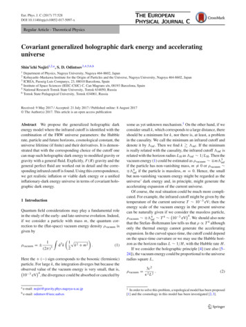
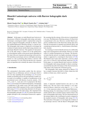
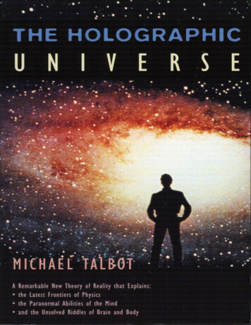
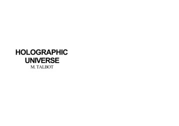
consists of a single holographic plate comprised of a series of thin vertical slit hologramsexposed one next to the other across the plate’s horizontal extent. Each slit is individuallyexposed to an image projected onto a rear-projection screen some distance away from theplate. Once the hologram is developed, each slit forms an aperture through which the imageof the projection screen at the time of that slit’s exposure can be seen. The images projectedonto the screen are usually views of an object captured from many different viewpoints.A viewer looking at the stereogram will see two different projection views through twoslit apertures, one through each eye. The brain interprets the differences between the twoviews as three-dimensional information. If the viewer moves side to side, different pairsof images are presented, and so the scene appears to gradually and accurately change fromone viewpoint to the next to faithfully mimic the appearance of an actual three-dimensionalscene.In the beginning of this chapter, the assumption will be made that the slit apertures areabout as wide as the pupil of the eye, and that when the viewer looks at the hologram eacheye sees through one and only one aperture at a time. During viewing, then, the viewer’sface must be right up against the surface of the plate, an awkward and inconvenient location,as shown in Figure 2.1. Later in this chapter, more convenient ways to view a holographicstereogram will be discussed.The holographic exposure setups used to expose all of the stereograms discussed in thischapter follow the same basic layout, similar to the common two beam off-axis holographicsetup used to make holograms of real objects. The layout is shown in Figure 2.2. Twobeams of mutually coherent light are used to expose the holographic recording material.The reference beam diverges from a point source at the same location as the one that willeventually be used to illuminate the hologram. The final hologram is to be illuminatedfrom above and behind; for practical reasons, the entire optical setup must be flipped “onits side” so that the illumination beam, and by direct consequence the reference beam, cantravel parallel to the table surface and yet strike the plate at the correct angle. The reference16
Figure 2.1: Viewing a simple stereogram requires that the viewer’s eyes be positioned atthe plane of the holographic plate.beam is collimated so that each slit of the holographic plate will be referenced with a beamof the same direction, independent of the slit’s precise lateral position on the plate.The object beam is diverged and used to project an image of the camera’s recordingmedium, typically photographic frames on cinéfilm, onto the projection screen. The projection screen serves as a two dimensional object that can be changed from view to view.The actual projected image, whose extent is defined by the projection frame, is the visiblesubregion of the projection screen in any particular view. The projection screen itself is asubregion of a plane of infinite extent called the projection plane.The projection screen directly faces the holographic plate and slit mechanism. Thedetails of this mechanism vary for different types of stereograms, but in all cases, theholographic plate is covered by a piece of optically opaque material with a slit-shaped holethat masks off all but a stripe for exposure. During exposure, this stripe is exposed both tothe image on the projection screen and to the reference source. Either the plate or the slit17
beamsplitterreference beamplate orslittransportcollimating lensobject beamlaserfilm transportholographicplatehorizontalslitrear projectionscreenprojection lensFigure 2.2: An above view of the general holographic table layout used for making thestereograms of the types described in this chapter.18
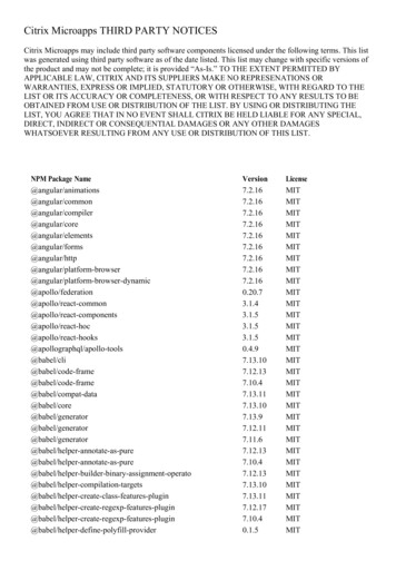
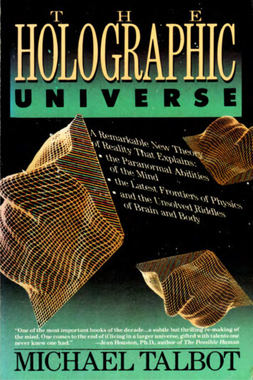
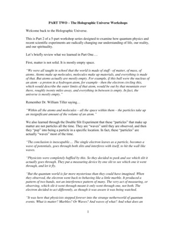
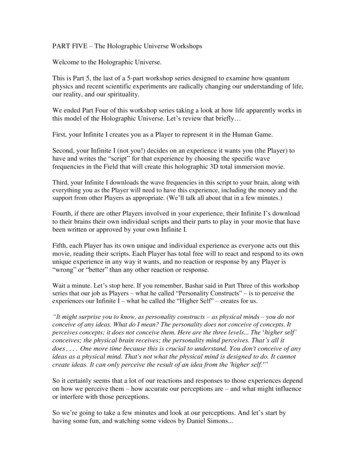
is moved between one exposure and the next so that the next adjacent stripe of holographicmaterial can be exposed.In display holo-stereography, the pictures imaged onto the projection screen areprojectional views of an object recorded with some sort of camera. For a point on anobject to be visible to the stereogram’s viewer from a particular viewpoint, the imageof that point must fall in the projection frame for the slit that corresponds to that viewlocation. Depending on the exact projection and exposure setup, the projection frame (orthe projection screen itself) may appear stationary as the viewer’s eye moves from view toview across the surface of the hologram; alternatively, the image of the projection framemay move across the viewer’s field of view as if it were at a finite distance from the plate.Because the setup is flipped sideways, images projected onto the screen must similarlyflipped. The top of the projected images must point towards the reference beam, whichdefines from where the eventual overhead illumination will come. “Top” on the projectionscreen, then, is toward the interior of the table, while “left” is into the table and “right” istoward the sky.Simple camera stereogramThe first example of a stereogram geometry centers the projection frame in front of eachslit being exposed during every exposure. When a stereogram made with this geometry isilluminated with the reference source, every slit forms an image of the projection screen thatis centered in front of it. Figure 2.3 shows several slits and the location of the projectionscreens that each slit forms. Such a stereogram can be produced with a holographicrecording apparatus that fixes the location of the slit aperture with respect to the projectionframe. The following exposing apparatus satisfies this geometrical constraint. The plate isfixed to a movable plateholder, and positioned behind a fixed horizontal slit aperture. Theprojection screen is centered in front of each slit. Figure 2.4 shows this setup.19
location of the projection frame when each slit is exposedstereogramwith slitsFigure 2.3: Three slits of a holographic stereogram using footage taken with a simplecamera. The projection screen is always centered in front of the slit being exposed duringexposure and viewing.The stereogram is exposed in the following way. The plateholder is positioned at theupper end of its travel so that the eventual leftmost slit is behind the slit aperture. The imageintended to be seen through the leftmost slit is projected onto the projection frame and areference beam simultaneously exposes the slit of hologram. The intensity and directionof light from every part of the projection frame is recorded as a latent image in the slitshaped area of holographic material. The movable plateholder is then repositioned so thatthe next unexposed segment of plate is behind the slit aperture, a new image is projectedonto the projection screen, and another exposure is made. The process continues until theentire width of the hologram has been exposed. After the plate is developed, the resultingdiffraction pattern on the emulsion (either a phase or an amplitude grating depending onthe type of processing used) will, when viewed with a collimated monochromatic sourceat the reference beam angle, appear as a sequence of slit-like windows, each presenting adifferent image that appeared on the projection screen.20
plate transportreference beamcollimatorreference beamTOPcondenser lensplate holder andholographic platefilm transportprojection lensprojection screenstationary slit maskFigure 2.4: Holographic table layout for simple camera geometry.21
How a stereogram displays depthA closer look at the details of this stereographic exposure provides some insight into howthe projectional views of an object should be captured so that the final stereogram producesan accurate three-dimensional image of that object. Imagine that the image projected onthe screen consisted of a single bright point centered in a field of black. Each slit of thestereogram is exposed to this test pattern with the bright point centered in front of it. Theimage neither changes nor moves with respect to the slit from one exposure to the next.When the final hologram is viewed, the viewer’s two eyes fall behind two different slitsof the hologram. The point appears to be directly in front of both of the viewer’s eyes.The viewer interprets the two images stereoscopically as if a single point were located atinfinity. This binocular depth cue is very strong; horizontal image parallax provides mostof the viewer’s depth sense. However, two other inaccurate depth cues provide conflictinginformation to the stereogram viewer. First, the viewer’s eyes must still focus on theprojection plane to focus on the point, so focus cues indicate that the point lies on theprojection plane. Second, because the slits are recorded horizontally, the plate records onlya single vertical perspective. The same perspective is presented independent of the viewer’svertical position. If the viewer moves vertically, the point will move as if it were locatedat the vertical projection plane. The precise significance of focus and vertical parallax cuesin stereograms has not been fully studied, but it appears to be minor compared to binocularcues.Stereogram camera geometryUsing the observation that a stationary point appears to be at infinity as a landmark, thecorrect camera geometry needed to accurately capture a three-dimensional scene can beinferred. To appear at infinity, then, an object point must remain at the same position in22
every camera view. This constraint implies that the camera should face the same direction,straight ahead, as each frame is captured. The camera moves along a track whose positionand length corresponds to the final stereogram plate. The camera takes pictures of a scenefrom viewpoints that corresponds to the the locations of the stereogram’s slits. The plateis planar, so the camera track must be straight, not curved. The camera must be able toimage the area corresponding to the projection frame onto its film; thus, the frame definesthe cross section of the viewing pyramid with its apex is located at the camera position, asshown in Figure 2.5. Because the projection frame bounds the camera’s image, the size ofthe projection frame and its distance from the slit determine the angle of view of the imageand thus the maximum (and optimal) focal length of the camera’s lens.The film plane of the stereogram capture camera is always parallel to the plane ofthe scene that corresponds to the projection plane (the capture projection plane) in orderto image it without geometric distortions onto the focal plane of the lens. If the film planewere tipped with respect to the projection plane when the image was captured, that imagethat appears on the film would be scaled vertically by an amount that varied from the leftside of the image to the right, turning the bounds of the projection frame into a shape thatresembles a sideways keystone. Keystone distortion is shown in Figure 2.6.The correspondence between the photographic capture and holographic exposuregeometries for the simple camera stereogram is shown in Figure 2.7. If this correspondenceis maintained, the images of all object points, not just points located far from the camera, willappear to be at the same depth as in the original scene. So a complicated three-dimensionalscene composed of many points will appear undistorted if correspondence between the twogeometries if maintained. To uniformly scale an object in all dimensions, the holographicrecording geometry can be a scale model of the photographic capture geometry. For properscaling between the two geometries, the angles A and B in Figure 2.7 should match. If thisrestriction is violated, one or more dimensions of the object will appear too great or toosmall in extent (for instance, the object’s depth may be exaggerated or reduced).23
projection screen formsa cross-section of theviewing pyramid foreach camera viewcamera as it moves alongtrack (one position shown)Figure 2.5: As the camera moves along the stereogram track, it images the space definedas a pyramid with apex at the current camera position and a cross-section defined by theprojection plane. The camera is always pointing directly ahead.24
undistorted imageThe image of the projectionplane and the film planeare not parallel whencaptured, but are so whenprojected. This leads toimage distortion.keystone distorted imageFigure 2.6: Keystone distortion occurs when the relationship between the film plane andthe projection plane is not maintained from photographic capture to holographic recording.Recentering camera stereogramsThe above stereogram exposure geometry is well suited for objects far from the camerabecause the image of the object wanders little from frame to frame, always remaining in thecamera’s field of view and thus always visible to the stereogram viewer. However, distantobjects are seldom the center of interest in three-dimensional images because the differentperspectives captured over the view zone have little disparity and, as a result, convey littlesense of depth. Objects at more interesting locations, closer to the camera, wander acrossthe frame from one camera view to the next and tend to be vignetted in the camera’s imageat either or both extremes of the camera’s travel. The solution to the problem is to alterthe capture camera to always frame the object of interest as it records the photographicsequence. Effectively, this change centers the object plane in every camera frame so that itremains stationary on the film from view to view. Object points in front of or behind thestationary plane will translate horizontally from view to view, but at a slower rate than theywould in a simple camera stereogram.25
AAprojectionplaneBarea corresponding to theholographic projection screenfor this particular camera view(screen is narrower thanusual for clarity)camera moving along trackThe image seen througheach slit is the imagethat was projected ontothe rear projection screen,which is centered in frontof each slit during eachexposure.AAprojectionplaneBholographicplate, exposedin slitsFigure 2.7: The relationship between holo-stereographic camera and recording geometries.26
projection screen is locatedin a fixed position with respectto the holographic plate for allslit exposures.stereogramwith slitsFigure 2.8: Three slits of a holographic stereogram exposed using a recentered camerageometry.Altering the camera geometry requires changes in the holographic exposure geometryneeded to produce undistorted images. The projection screen is no longer centered in frontof the slit aperture during all exposures. Instead, the holographic plate holder is stationaryand the slit in front of it moves from exposure to exposure. Thus, the projection frame isfixed in space relative to the plate for all exposures, rather than being centered in front of eachslit during each exposure. In this geometry, called the “recentered camera” geometry, onlyone projection frame position exists for all slits, as shown in Figure 2.8. Holographically,such a stereogram can be realized using a table layout like that shown in Figure 2.9.Because the projection frame and the plate are fixed with respect to each other forevery slit exposure, the projection frame appears to be at its true, physical location in space.If the bright point on a black field is projected onto the screen and all the slits are exposedto that image, the point will appear not at infinity as before, but at the projection planedistance instead just as if it were a hole cut into a black card. In effect, as the viewerlooks at the final stereogram, the projection frame no longer seems to follow the viewer butinstead appears stationary in space. If an image of the object plane of the original scene27
slit transportreference beamcollimatorreference beamTOPcondenser lensstationary plate holderand holographic platefilm transportprojection lensprojection screenmoving slit mask(with flexible bottom)Figure 2.9: Holographic table layout for a recentered stereogram.28
remains stationary on the projection screen, then, the object plane of the original scene andthe projection plane of the final hologram will lie at the same depth.Recentering camerasThe type of camera necessary to take pictures for this type of stereogram is based on, butmore complicated than, the simple camera used to capture the infinitely distant object. Thisnew type of camera is called a recentering camera. Recall that in the simple camera imagecapture, the image of a nearby object point translated across the camera’s film plane as thecamera moved down its track taking pictures. In a recentering camera, the lens and thefilm back of the camera can move independently from each other, so the film plane canbe translated at the same rate as the image of the object of interest. The film and imagemove together through all frames, so just as desired the image appears stationary in all theresulting images. A view camera with a “shifting” or “shearing” lens provides this type
the two-step transfers of stereograms made by King, Noll and Berry[8] in 1970. Although some modifications have been made to the stereogram's holographic exposure geometry, and some attempts have been made to understand and compensate for the distortions that occur in stereograms [4][13][14][6], the behavior of the stereogram's optical .