Transcription
Raspberry PI Stepper MotorConstructors ManualBob Rathbone Computer Consultancywww.bobrathbone.com4th of January 2014Bob Rathbone Raspberry PI Stepper Motors1
ContentsIntroduction . 4Raspberry PI computer . 4Stepper Motor Theory . 5Types of stepper motor . 5Unipolar stepper motors. 5Bipolar stepper motors . 5Unipolar driver circuit . 6Wave drive . 6Full step drive . 6Half stepping . 6Microstepping . 6Bipolar stepper motor driver . 7Motor driver boards. 8Unipolar driver boards . 8Construction. 9Source code and usage . 12motor class.py . 12test motor class.py. 12motor i2c class.py . 13test motor ic2 class.py . 13motord.py . 13motor daemon.py . 13The Log class . 13Software installation . 14Software download . 14Installing the I2C libraries . 14Configure motord.py program log rotation . 15The MCP23017 expander board . 16The MCP23017 chip . 16MCP2317 and Ciseco Board signals . 17Appendix A Code Listings . 18Bob Rathbone Raspberry PI Stepper Motors2
Appendix B Licences. 19Acknowledgements. 19Glossary . 20Bob Rathbone Raspberry PI Stepper Motors3
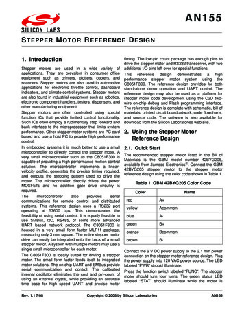
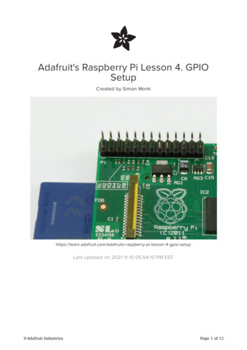
IntroductionThis project has been designed to help students or hobbyists get started with driving stepper motorson the Raspberry PI. It covers two types of stepper motor namely unipolar and bipolar. Thedifference between these two is explained in the next section. The principle hardware required torun stepper motors on a Raspberry PI consists of the following components: A Raspberry PI computerA single or dual stepper motor driver boardAs alternative to the above an I2C interface can be usedOne or two 5-Wire "28BYJ-48" stepper Motor (bipolar motor)A 12 volt #324 stepper motor (unipolar motor)Object orientated Python driver codeRaspberry PI computerThe Raspberry Pi is a credit-card-sized single-board computer developed in the United Kingdom bythe Raspberry Pi Foundation with the intention of promoting the teaching of basic computer sciencein schools.Figure 1 Raspberry PI ComputerMore information on the Raspberry PI computer may be found here:http://en.wikipedia.org/wiki/Raspberry PiIf you are new to the Raspberry PI try the following beginners guide. http://elinux.org/RPi BeginnersBob Rathbone Raspberry PI Stepper Motors Introduction4
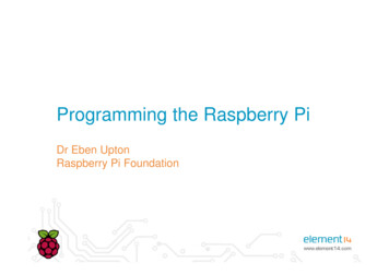
Stepper Motor TheoryTypes of stepper motorA good place to start is the following Wikipedia Article:http://en.wikipedia.org/wiki/Stepper motorThere are two types of stepper motor in popular use. These are:1. Unipolar stepper motors typically driven using single transistors or Darlington pairs2. Bipolar motors typically driven using an H-bridge circuitUnipolar stepper motorsFigure 2 A 5-Wire 28BYJ-48 Stepper Motor WiringThe 28BYJ-48 stepper motor is a so-calledunipolar motor. A unipolar stepper motor hastwo or more windings, each with centre tap.Each section of windings is switched on for eachdirection of magnetic field. Since in thisarrangement a magnetic pole can be reversedwithout switching the direction of current, thecircuit can be made very simple (e.g., a singletransistor) for each winding. In this project theULN2803A Integrated Circuit is used. This is aneight Darlington pair driver circuit.Bipolar stepper motorsFigure 3 A 4-Wire Bipolar Stepper Motor WiringBipolar stepper motors have a single winding perphase. The current in each winding needs to bereversed in order to reverse the magnetic pole,so the driving circuit is more complicated,typically with an H-bridge arrangement,however there are several off-the-shelf driverchips available to make this a simple affair. Thisproject is using the A4988 H-bridge circuit driverboard. There are two leads per phase, none arecommon. Bipolar motors are more efficient thanunipolar motors as both phases are used atonce. They can deliver higher torque and speedthan a unipolar motor of the same weight.Bob Rathbone Raspberry PI Stepper Motors Stepper Motor Theory5
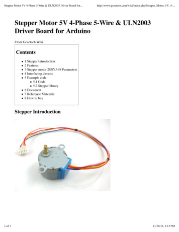
Unipolar driver circuitThere are a number of ways to drive a unipolar stepper motor as shown belowFigure 4 Unipolar stepper motor drive methodsWave driveIn this drive method only a singlephase is activated at a time. It is thefastest drive method but is rarely used.Full step driveThis is the usual method for full stepdriving the motor. Two phases arealways on so the motor will provide itsmaximum rated torque.Half steppingWhen half stepping, the drivealternates between two phases on anda single phase on. This increases theangular resolution, but the motor alsohas less torque.MicrosteppingHere the windings are driven withsinusoidal AC waveform to givesmoother operation. This requiresdifferent hardware and isn’t used inthis project.Bob Rathbone Raspberry PI Stepper Motors Stepper Motor Theory6
Bipolar stepper motor driverThis project uses the A4988 H-circuit driver board.Figure 5 A4988 driver circuitGPIOI pinSignalSTEPBob Rathbone Raspberry PI Stepper Motors Stepper Motor Theory7
Motor driver boardsUnipolar driver boardsA number of stepper motor driver boards are available.This board is available from ModMyPi and usesthe ULN2803A Eight Darlington outputs DriverChip. It can drive two stepper motors. This boardcan drive unipolar devices up to 50 volts.This is an example of a single stepper motordriver board. It uses four outputs of a ULN2003ASeven Darlington outputs Driver Chip. It is piggybacked on top of a slice of ModPi prototypeboard using a glue gun. This allows it to beplugged into the GPIO header of theThis example shows the I2C interface using a 16port MCP23017 I/O expander available fromModMyPi or Ciseco. It is connecting to the abovesingle stepper motor driver board. Sixteen I/Oports mean that this board can drive up to fourmotors using only two pins (I2C) on theRaspberry PI. Since I2C can support up to eightdevices many more motors can be driven.The diagram on the left shows the ULN2803AEight Darlington outputs Driver Chip. This chipcan drive two bipolar stepper motors (fouroutputs used for each motor.Bob Rathbone Raspberry PI Stepper Motors Motor driver boards8
ConstructionFigure 6 Unipolar motor and driverboardThe unipolar stepper motor board uses 8 I/O pins to driveup to two stepper motors.The jumper shipped with the board allows the steppermotor to use the 5V from the Raspberry PI. If you want touse a different stepper you can remove the jumper andsupply up to 12 volts to the centre pin and connect groundto the pin that had no connection.The left white five pin connector is for the first motor andthe right connector is for the second motor.Table 1 GPIO interface wiringGPIO r 1 output 1Motor 1 output 2Motor 1 output 3Motor 1 output 4Motor 2 output 1Motor 2 output 2Motor 2 output 3Motor 2 output 4The driver board comes as a kit. Not shown isa small stick on plastic pad to prevent the cardshorting on the Raspberry PI board.Install and solder IC socket first. Orientate thenotch at one end of the socket to the left sideof the board.Bob Rathbone Raspberry PI Stepper Motors Motor driver boards9
Install resistor pack. Be sure to orient it asshown. I.E. the text on the resistor pack cannot be seen from this side.Install white connectors. Be sure to orientthem as shown.Install LED's. Be sure to orient them as shown.Long Leg towards resistor pack.Insert and solder the capacitor. Solder the 26pin female socket to the underside of theboard as shown above. Insert the ULN2803AMotor Driver Chip with the notch towards thecapacitor. Insert and solder the power supplypins and insert the jumper as shown. Finallystick the plastic pad underneath the resistorblock in such a way that it rests on the powersupply capacitor on the Raspberry PI board.Bob Rathbone Raspberry PI Stepper Motors Motor driver boards10
The bipolar driver boardThe A4988 H-Bridge driver board comes as asimple kit. Break the in-line connector in halfand solder the short pins into the board. Thelong pins can then connect directly into abreadboard or can be connected via matchingfemale connectors into an interface PCB such asthe ModMyPi Humble PI.You can solder the pins as shown or turn theboard upside down and solder the pins in fromthe other side so that you can read the pinnames which is much more convenient.Bob Rathbone Raspberry PI Stepper Motors Motor driver boards11
Source code and usageThe code for driving the motor comes as a number of separate source files.motor class.pyThis is the actual code that drives the motor using the GPIO pins. It is called in other programs. Touse the class in a program first import it and define the motor(s). In the following we define twomotors and the GPIO pins they will be using.from motor class import Motormotora Motor(17,18,27,22)motorb Motor(4,25,24,23)Before a motor can be used it must be initialised. This sets up the GPIO pins.motora.init()To turn the motor one revolution clockwise:motora.turn(1*Motor.REVOLUTION, Motor.CLOCKWISE)To turn the motor two revolutions anti-clockwise:motora.turn(2*Motor.REVOLUTION, Motor.ANTICLOCKWISE)To turn the motor two steps anti-clockwise:motora.turn(2, Motor.ANTICLOCKWISE)The above turns the shaft 0.7 degrees per step (360/512 0.703125 Degrees)The motor has 512 positions. To turn the motor to a particular position (200 in this case):motora.goto(200)To lock the motor in its current position:motora.lock()To stop an already turning motor:motora.interrupt()To set the type of stepping (See Stepper Motor Theory on page 5) use one of the following rive()motora.setWaveDrive()The default is Full Step Drive. It isn’t necessary to set this as it is the default.test motor class.pyThis contains simple examples of driving two motors using the dual motor driver board.Bob Rathbone Raspberry PI Stepper Motors Source code and usage12
motor i2c class.pyThis class does the same as the motor class.py code but uses the i2C interface.test motor ic2 class.pyThis class does the same as the test motor class.py code but uses the i2C interface. However themotor definitions are different. The MCP23017 I/O expander chip has two banks of eight I/O portsmaking sixteen in all which allows up to four motors to be driven per MCP23017 I/O expander.address 0x20 # I2C address of MCP23017motora Motor(address,Motor.MOTOR A)motorb Motor(address,Motor.MOTOR B)motorc Motor(address,Motor.MOTOR C)motord Motor(address,Motor.MOTOR D)The address parameter is normally Hex 0x20 for the MCP23017 I/O expander chip. See TheMCP23017 chip on page 16 and Installing the I2C libraries on page 14 for more information.motord.pyThe motord.py program is a more complex example of driving two motors concurrently. Each motoris handled by a separate (forked) process. This allows the motors to be turned at the same time.Just invoking the program displays its usage. sudo ./motord.pyusage: ./motord.py start stop restart status versionTo start and stop the motor daemon, use the following code. sudo ./motord.py start sudo ./motord.py stopNote: The current motor command will be always completed when the stop command is issued.If the motord daemon is running then issuing the status command will display its PID. sudo ./motord.py statusMotor daemon running pid 2813The pid will be different each time the motord program is run.The version command shows the current version of the software. sudo ./motord.py versionVersion 1.0motor daemon.pyThis is the code to create the daemon process and to start and stop it. It is used by the motord.pyprogram only.The Log classThe log class.py routine provides logging of events to /var/log/motor.log file. It is used by themotord.py program only.Bob Rathbone Raspberry PI Stepper Motors Source code and usage13
Software installationThis procedure assumes that the Raspberry PI is installed with Debian Wheezy and with a workingInternet Connection. There are several steps to carry out to install the software. Download and un-tar the software from the Bob Rathbone web siteOptionally install I2C library (If using the I2C programs)Software downloadThe software is contained in a compressed tar file called pi stepper motor.tar.gz. This can bedownloaded from the following location.http://www.bobrathbone.com/raspberrypi stepper.htmEither download it to the PC and copy it across to the Raspberry PI or use the wget facility if there isan Internet connection on the Raspberry PI.Create a directory called /home/pi/stepper. Copy the pi stepper motor.tar.gz tothe /home/pi/stepper directory or use wget to download it.# wget http://www.bobrathbone.com/raspberrypi/source/pi stepper motor.tar.gzUn-tar the file with the following command:# tar -xvf pi stepper motor.tar.gzThis will unzip the following files and directory:log class.py, motor daemon.py, motor i2c class.py, motor class.py, motord.py,test motor class.py, test motor ic2 class.py.Installing the I2C librariesIf you are using the motor i2c class.py program it is necessary to install the I2C libraries. If not thenskip this section.Edit /etc/modules file and add the following lines to the end of the file. Then save and reboot toenable the hardware I2C driver.i2c-bcm2708i2c-devEnter the following commands to add SMBus support (which includes I2C) to Python:sudo apt-get install python-smbussudo apt-get install i2c-toolsThe i2c-tools isn't strictly required, but it's a useful package since you can use it to scan for any I2C orSMBus devices connected to the Raspberry. If you know something is connected, but you don'tknow it's 7-bit I2C address, this library has a great little tool to help you find it:sudo i2cdetect -y 0 (if you are using a version 1 Raspberry Pi)Bob Rathbone Raspberry PI Stepper Motors Software installation14
sudo i2cdetect -y 1 (if you are using a version 2 Raspberry Pi)This will search /dev/i2c-0 or /dev/i2c-1 for all address, and if the ModMyPi I2C interface is correctlyconnected, it should show up at 0x20.Once both of these packages have been installed, you have everything you need to get startedaccessing I2C and SMBus devices in Python.Configure motord.py program log rotationIf you will not be using the radiod.py daemon skip this section.The Radio program logs to a file called /var/log/motor.log. This can eventually fill the SD card.Create a file called /etc/logrotate.d/motor with the following lines:/var/log/motor.log {weeklymissingokrotate 7compressnotifemptycopytruncatecreate 600}This will rotate the log files every week so prevent the SD card from eventually filling up.Bob Rathbone Raspberry PI Stepper Motors Software installation15
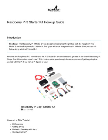
The MCP23017 expander boardIf you are connecting the stepper motor using the I2C interface then you will need an I/O expanderboard.There are a number of expander boards available as shown in the following figure. For this projectwe are using the one shown on the right from Ciseco.Figure 7 MCP23017 expander boardsPlease note in this picture the B0 to B7 outputs are labelled the wrong way round. B7 at the bottomshould be B0 and so on.The MCP23017 chipThe following diagram shows the pin outs for the MCP23017Figure 8 The MCP23017 chipBob Rathbone Raspberry PI Stepper Motors The MCP23017 expander board16
There are two output banks A and B of 8 pins each. The I²C interface consists of a data (SDA) andclock (SCL). The chip has up to eight addresses by biasing the A0, A1 and A2 lines. The fullspecification for the MCP23017 chip can be found /21952b.pdfMCP2317 and Ciseco Board signalsThe MCP2317 chip has 16 input/output pins as shown in the following table. This shows the hex,decimal or binary values that have to be written to the MCP2317 chip enable the outputs. Thebanks A and B are addressed by 0x12 and 0x13 respectively (See example program listings inappendix 7Pin123456782122232425262728Ciseco BoardA0A1A2A3A4A5A6A7B0 (B7)B1 (B6)B2 (B5)B3 (B4)B4 (B3)B5 (B2)B6 (B1)B7 000000Note: The first batch of Ciseco expander boards have B0-B7 labelled the wrong way round. Thenumbers in brackets are the incorrect labelling. Watch out for this. Later batches of this boardshould be correct.If for example you wish to enable I/O 9 (GPB0) and 10 (GPB1) together you must enable bank 1 andthen either add the decimal values together. 1 2 3 Hex 0x3 binary 00000011.Bob Rathbone Raspberry PI Stepper Motors The MCP23017 expander board17
Appendix A Code ListingsAll code can be downloaded from the following i stepper motor.tar.gzBob Rathbone Raspberry PI Stepper Motors Appendix A Code Listings18
Appendix B LicencesThe software and documentation for this project is released under the GNU General Public Licence.The GNU General Public License (GNU GPL or GPL) is the most widely used free software license,which guarantees end users (individuals, organizations, companies) the freedoms to use, study,share (copy), and modify the software. Software that ensures that these rights are retained is calledfree software. The license was originally written by Richard Stallman of the Free SoftwareFoundation (FSF) for the GNU project.The GPL grants the recipients of a computer program the rights of the Free Software Definition anduses copyleft to ensure the freedoms are preserved whenever the work is distributed, even whenthe work is changed or added to. The GPL is a copyleft license, which means that derived works canonly be distributed under the same license terms. This is in distinction to permissive free softwarelicenses, of which the BSD licenses are the standard examples. GPL was the first copyleft license forgeneral use.See http://www.gnu.org/licenses/#GPL for further information on the GNU General Public License.AcknowledgementsThanks to the numerous Raspberry PI contributors who have placed articles about driving steppermotors using the Raspberry PI on their websites and blogs for the benefit of the community.Bob Rathbone Raspberry PI Stepper Motors Appendix B Licences19
GlossaryGPIOGeneral Purpose IO (On the Raspberry PI)ICIntegrated CircuitLEDLight Emitting DiodePIDProcess Identification NumberBob Rathbone Raspberry PI Stepper Motors Glossary20
Raspberry PI computer The Raspberry Pi is a credit-card-sized single-board computer developed in the United Kingdom by the Raspberry Pi Foundation with the intention of promoting the teaching of basic computer science in schools. Figure 1 Raspberry PI Computer More information on the