Transcription
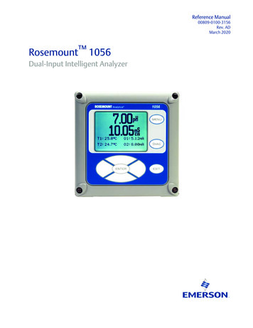
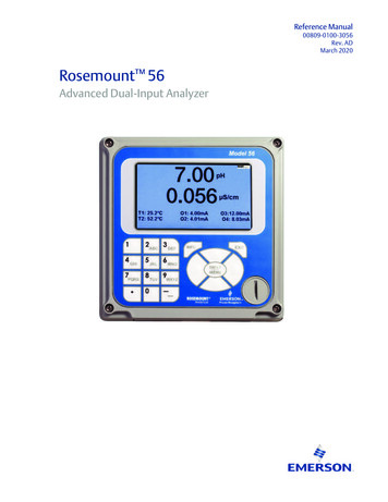
Reference Manual00809-0100-3056Rev. ADMarch 2020Rosemount 56Advanced Dual-Input Analyzer
Essential InstructionsRead this page before proceedingYour instrument purchase from Emerson is one of the finest available for your particular application. These instrumentshave been designed, and tested to meet many national and international standards. Experience indicates that its performance is directly related to the quality of the installation and knowledge of the user in operating and maintaining the instrument. To ensure their continued operation to the design specifications, personnel should read this manual thoroughlybefore proceeding with installation, commissioning, operation, and maintenance of this instrument. If this equipment isused in a manner not specified by the manufacturer, the protection provided by it against hazards may be impaired. Failure to follow the proper instructions may cause any one of the following situations to occur: Loss of life; personal injury; property damage; damage to this instrument; and warranty invalidation. Ensure that you have received the correct model and options from your purchase order. Verify that this manualcovers your model and options. If not, call 1-800-854-8257 or 949-757-8500 to request correct manual. For clarification of instructions, contact your Rosemount representative. Follow all warnings, cautions, and instructions marked on and supplied with the product. Use only qualified personnel to install, operate, update, program and maintain the product. Educate your personnel in the proper installation, operation, and maintenance of the product. Install equipment as specified in the Installation section of this manual. Follow appropriate local and national codes.Only connect the product to electrical sources specified in this manual. Use only factory documented components for repair. Tampering or unauthorized substitution of parts and procedures can affect the performance and cause unsafe operation of your process. All instrument enclosures must be closed and protective covers must be in place unless qualified personnel are performing maintenance.WARNINGRISK OF ELECTRICAL SHOCKEquipment protected throughout by double insulation. Installation and servicing of this product may expose personnel to dangerous voltages. Main power wired to separate power source must be disconnected before servicing. Do not operate or energize instrument with case open! Signal wiring connected in this box must be rated at least 240 V for European mains operation. Non-metallic cable strain reliefs do not provide grounding between conduit connections! Use grounding type bushings and jumper wires. Unused cable conduit entries must be securely sealed by non-flammable closures to provide enclosure integrity in compliance with personal safety and environmental protection requirements. Unused conduit openings must be sealed withType 4X or IP66 conduit plugs to maintain the ingress protection rating (Type 4X) Electrical installation must be in accordance with the National Electrical Code (ANSI/NFPA-70) and/or any otherapplicable national or local codes. Operate only with front panel fastened and in place. Safety and performance require that this instrument be connected and properly grounded through a three-wire powersource. Proper use and configuration is the responsibility of the user.
CAUTIONThis product generates, uses, and can radiate radio frequency energy and thus can cause radio communication interference. Improper installation, or operation, may increase such interference. As temporarily permitted by regulation, this unit has not been tested for compliance within the limits of ClassA computing devices, pursuant to Subpart J of Part 15, of FCC Rules, which are designed to providereasonable protection against such interference. Operation of this equipment in a residential area maycause interference, in which case the user at his own expense, will be required to take whatever measures may be required to correct the interference.WARNINGPhysical accessUnauthorized personnel may potentially cause significant damage to and/or misconfiguration of end users’ equipment. This could be intentional or unintentional and needs to be protected against.Physical security is an important part of any security program and fundamental to protecting your system. Restrict physical access by unauthorized personnel to protect end users’ assets. This is true for all systems used within the facility.
Section i: Quick Start Guide1. Refer to Section 2.0 for mechanical installation instructions.2.Wire sensor(s) to the signal boards. See Section 3.0 for wiring instructions. Refer to thesensor instruction sheet for additional details. Make current output, alarm relay andpower connections3. Once connections are secured and verified, apply power to the analyzer.WARNINGRISK OF ELECTRICAL SHOCKElectrical installation must be in accordance with the National Electrical Code(ANSI/NFPA-70) and/or any other applicable national or local codes.CAUTION: This symbol identifies a risk of electrical shock.CAUTION: This symbol identifies a potential hazard. When this symbol appears,consult the manual for appropriate action.4. When the analyzer is powered up for the first time, Time/Date and Quick Start screensappear. Quick Start operating tips are as follows:a. Window screens will appear. The field with the focus will appear with dark blue backlighting. The field with focus can be edited by press ENTER/MENU.b. The Time and Date screen to set the real-time clock will appear. Accept the displayedtime by pressing ENTER on Time and date OK or press the down key to Change thetime and date.c. The first Quick Start screen appears. Choose the desired language by pressingENTER/MENU to edit the active field and scrolling to the language of choice. PressENTER/MENU and press the down arrow to highlight NEXT.d. The Navigation Rules for operating the keypad will be displayed.e. Choose the measurement for Sensor 1 (and Sensor 2) and proceed to the remainingQuick Start steps.f. Keypad operation guidelines will appear to guide the user how operate the user interface.g. NOTE: To edit a field with backlit focus, press ENTER/MENU. To scroll up or down, usethe keys to above or below the ENTER key. To move the cursor left or right, use thekeys to the left or right of the ENTER key. To edit a numeric value including decimalpoints, use the alphanumeric keypad then press ENTER.h. NOTE: Press ENTER to store a setting or value. Press EXIT to leave without storingchanges. Pressing EXIT during Quick Start returns the display to the initial start-upscreen (select language). To proceed to the next Quick Start step, use the right key orthe down key to highlight NEXT. Press ENTER.5.After the last step, the main display appears. The current outputs are assigned to defaultvalues before probes are wired to the analyzer. After the last step, the main display appears. The outputs are assigned todefault values.6. To change output, and all settings, press ENTER/MENU from the live screen. Using thedown and right arrow keys, select one of the following menus and navigate the screen ofchoice.7. To return the analyzer to the default settings, choose Reset under the Menu selectionscreen.
SAFETY MESSAGESProcedures and instructions in this section may require special precautions to ensure thesafety of the personnel performing the operations. Information that raises potential safetyissues is indicated by a warning symbol (). This symbol identifies a potential hazard.
Reference ManualTable of Contents00809-0100-3056March 2020ContentsSection 1: Description and .121.13Features and Applications.1Enhanced Features .2Specifications-General .3Contacting Conductivity .6Toroidal Conductivity .7pH/ORP .8Flow .94-20 mA Current Input.9Chlorine.10Dissolved Oxygen .12Dissolved Ozone.12Turbidity.13Ordering Information .14Section 2: Installation2.1 Unpacking and Inspection .152.2 Installation .15Section: 3 Wiring3.13.23.33.4General .21Preparing Conduit Openings .22Preparing Sensor Cable.22Power, Output, Alarms and Sensor Connections.22Section 4: Display and Operation4.14.24.34.44.54.64.74.8User Interface .31Instrument Keypad .31Main Display .31Menu System.32USB Data Port .3356 Data Logger and Event Logger Download Procedure .33Software Upgrade .35Configuration Transfer .35Section 5: Programming the Analyzer - Basics5.15.25.35.45.55.65.75.85.9Table of ContentsGeneral .37Changing the Startup Settings .37Programming Temperature .38Configuring and Ranging the Current Outputs .38Setting a Security Code .39Security Access.39Using Hold .40Resetting Factory Defaults – Reset Analyzer .40Programming Alarm Relays. .40i
Table of ContentsReference ManualMarch 202000809-0100-3056Section 6: Programming - Measurements6.1 Programming Measurements – Introduction .436.2 pH .436.3 ORP .446.4 Contacting Conductivity.456.5 Toroidal Conductivity .466.6 Chlorine.476.7 Dissolved Oxygen .506.8 Dissolved Ozone .516.9 Turbidity .516.10 Flow .526.11 Current Input .52Section 7: PID Control7.1 Introduction .557.2 PID Setup.59Section 8: Time Proportional Control8.1 Introduction .638.2 TPC Setup.63Section 9: Alarm Relay Functions9.1 General.679.2 High/Low Concentration Alarm .679.3 Delay Timer: .
widest range of liquid measurement inputs and digital communications available. The 56 advanced dual-input analyzer supports continuous measurement of liquid ana lytical inputs from one or two sensors. The modular design allows signal input boards to be field re placed, making configuration changes easy. The high resolution full-color display gives
