Transcription
Liebert GXT5 UPS120 V Input, 120 V OutputLVInstaller/User Guide
The information contained in this document is subject to changewithout notice and may not be suitable for all applications.While every precaution has been taken to ensure the accuracyand completeness of this document, Vertiv assumes noresponsibility and disclaims all liability for damages resultingfrom use of this information or for any errors or omissions. Referto other local practices or building codes as applicable for thecorrect methods, tools, and materials to be used in performingprocedures not specifically described in this document.The products covered by this instruction manual aremanufactured and/or sold by Vertiv. This document is theproperty of Vertiv and contains confidential and proprietaryinformation owned by Vertiv. Any copying, use or disclosure ofit without the written permission of Vertiv is strictly prohibited.Names of companies and products are trademarks or registeredtrademarks of the respective companies. Any questionsregarding usage of trademark names should be directed to theoriginal manufacturer.Technical Support SiteIf you encounter any installation or operational issues with your product, check the pertinent section of thismanual to see if the issue can be resolved by following outlined procedures.Visit https://www.vertiv.com/en-us/support/ for additional assistance.
Table of ContentsImportant Safety Information 1Chapter 1: GXT5 Description 31.1. UPS Features and Available Models 31.2. Front Panels 41.3. Rear Panels 41.4. Battery Cabinet 71.5. Major Internal Components and Operating Principle 71.6. UPS States and Operating Modes 91.6.1. Normal Mode 91.6.2. Bypass Mode 91.6.3. Battery Mode 91.6.4. Frequency Converter Mode 91.6.5. ECO Mode 10Chapter 2: Installation 112.1. Unpacking and Inspection 112.2. Pre-installation Preparation 112.2.1. Installation Clearances 112.3. Installing the UPS 122.3.1. Tower Installation 122.3.2. Rack Installation 132.4. Installing External Battery Cabinets 132.5. Connecting AC Input Power 152.6. Communication Connections 16Vertiv Liebert GXT5 Installer/User Guidei
2.6.1. Connecting IntelliSlot Communication 162.6.2. Connecting to the Dry-contact Port 162.6.3. Connecting a Remote Emergency Power-off (REPO) Switch 182.6.4. Connecting a USB Cable 192.6.5. Connecting CLI Communication Cables 19Chapter 3: Operating the UPS 213.1. Silencing the Audible Alarm 213.2. Starting-up the UPS 213.3. Transferring to Battery Mode 223.4. Transferring from Normal to Bypass Mode 223.5. Transferring from Bypass to Normal Mode 223.6. Shutting-down the UPS Completely 233.7. Remote Emergency Power-off (REPO) 23Chapter 4: Operation and Display Panel 254.1. LED Indicators 274.2. LCD Menu and Screens 274.2.1. Start-up and Flow Screens 274.2.2. Main Menu 284.2.3. Status Screen 294.2.4. Settings Submenu 324.2.5. Control Screen 414.2.6. Log Screen 424.2.7. About Screen 454.3. Editing Display and Operation Settings 474.3.1. Settings Prompts 47iiVertiv Liebert GXT5 Installer/User Guide
4.3.2. Changing the Password 484.3.3. Selecting the Display Language 484.3.4. Setting the Date and Time 49Chapter 5: Maintenance 515.1. Replacing Batteries 515.2. Charging Batteries 535.3. Checking UPS Operation 545.4. Cleaning the UPS 545.5. Firmware Updates 545.5.1. Updating Firmware with RDU101 Card Connection
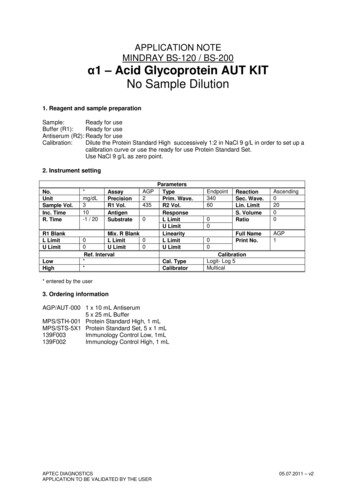
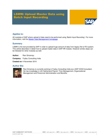
Vertiv Liebert GXT5 Installer/User Guide 5 Figure 1-3 GXT5-2000LVRT2UXL Rear Panel ITEM DESCRIPTION 1 Liebert IntelliSlot port 2 USB port 3 Un-used 4 External-battery connector 5 Non-programmable output receptacles, NEMA 5-20R 6 Programmable output receptacles, NEMA 5-20R 7 Input circuit breaker 8 Input-power plug and cable, NEMA L5-20P