Transcription
Chapter 31Alternating CurrentCircuits
Alternating Current Circuits Alternating Current - Generator Wave Nomenclature & RMS AC Circuits: Resistor; Inductor; Capacitor Transformers - not the movie LC and RLC Circuits - No generator Driven RLC Circuits - Series Impedance and Power RC and RL Circuits - Low & High Frequency RLC Circuit - Solution via Complex Numbers RLC Circuit - Example ResonanceMFMcGraw-PHY 2426Chap31-AC Circuits-Revised: 6/24/20122
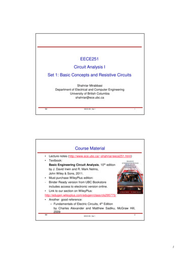
GeneratorsBy turning the coils in the magnetic field an emf isgenerated in the coils thus turning mechanical energy intoalternating (AC) power.MFMcGraw-PHY 2426Chap31-AC Circuits-Revised: 6/24/20123
GeneratorsRotating the Coil in a Magnetic Field Generates an Emf Examples: Gasoline generator Manually turning the crank Hydroelectric powerMFMcGraw-PHY 2426Chap31-AC Circuits-Revised: 6/24/20124
Generatorsφm NBAcosθθ ωtφm NBAcosωtd - φm NBAωsinωtdt sinωt; NBAωεε εMFMcGraw-PHY 2426peakChap31-AC Circuits-Revised: 6/24/2012εpeak5
Wave Nomenclature and RMSValuesMFMcGraw-PHY 2426Chap31-AC Circuits-Revised: 6/24/20126
Wave NomenclatureApeak-peak Ap-p 2Apeak 2Ap; Ap Ap-p /2MFMcGraw-PHY 2426Chap31-AC Circuits-Revised: 6/24/20127
Shifting Trig Functions sin x A ωt - ϕ cos x AThe minus sign means that thephase is shifted to the right.sin t 2πϕ cos T{ }A plus sign indicated the phaseis shifted to the leftx A sin ωt - π2 x A ( sinωt cos π2 - sin π2 cosωt )x A ( sinωt (0) - (1)cosωt )x -AcosωtMFMcGraw-PHY 2426Chap31-AC Circuits-Revised: 6/24/20128
Shifting Trig Functions π sin ωt - 02 Shifted Trig Functions1.50πωt - 02πωt 2π 11Tt ; ω 2π2ωπ TTt 2 2π 4MFMcGraw-PHY 0.001.002.003.00-0.50-1.00-1.50TimeChap31-AC Circuits-Revised: 6/24/20129
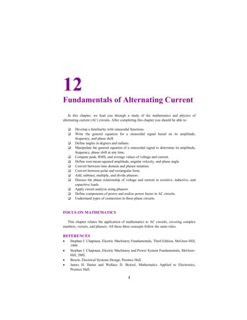
Root Mean SquaredThe root mean squared (rms) method of averaging isused when a variable will average to zero but its effectwill not average to zero.Procedure Square it (make the negative values positive) Take the average (mean) Take the square root (undo the squaring operation)MFMcGraw-PHY 2426Chap31-AC Circuits-Revised: 6/24/201210
Root Mean Squared AverageSine IN(Theta)SIN2(Theta)RMS Value-1.0-1.5Angle (Radians)MFMcGraw-PHY 2426Chap31-AC Circuits-Revised: 6/24/201211
Average of a Periodic FunctionTV VavgVavg1 V(t)dt; V(t) V p sinωtT oTVp1 V p sinωtdt T oωTVavg -VpωTωT sinxdx 0VpωTcos(ωT) d(cosx)cos(0)(1 - 1) 0MFMcGraw-PHY 2426Chap31-AC Circuits-Revised: 6/24/201212
Root Mean SquaredTV( )2 V( )V2( )V2avgavg avgV p2TT sin 2 ωtdt oV p2ωTπ V p22V p2VRMS MFMcGraw-PHY 24261 V 2 (t)dt; V(t) V p sinωtT o22(V )2avg 12V p 0.707V pChap31-AC Circuits-Revised: 6/24/201213
Root Mean SquaredRootVRMS Square(V )2avg1 V p 0.707V p2MeanThe RMS voltage (VRMS )is the DC voltage that has the sameeffect as the actual AC voltage.MFMcGraw-PHY 2426Chap31-AC Circuits-Revised: 6/24/201214
RMS PowerPavg1 Vp I p2sincePavgPavgVRMS Vp1 2 VRMS2 VRMS I RMS(2)(and I RMS 2 I RMSIp2)The average AC power is the product of the DC equivalentvoltage and current.MFMcGraw-PHY 2426Chap31-AC Circuits-Revised: 6/24/201215
Resistor in an AC CircuitMFMcGraw-PHY 2426Chap31-AC Circuits-Revised: 6/24/201216
Resistor in an AC CircuitFor the case of a resistor in an AC circuit the VR across theresistor is in phase with the current I through the resistor.In phase means that both waveforms peak at the same time.MFMcGraw-PHY 2426Chap31-AC Circuits-Revised: 6/24/201217
Resistor in an AC CircuitP(t) I (t)R ( I cosωt ) R22p2P(t) I p2 RcosωtThe instantaneous power is a function of time. However, the averagepower per cycle is of more interest.MFMcGraw-PHY 2426Chap31-AC Circuits-Revised: 6/24/201218
Inductors in an AC CircuitMFMcGraw-PHY 2426Chap31-AC Circuits-Revised: 6/24/201219
Coils & Caps in an AC CircuitMFMcGraw-PHY 2426Chap31-AC Circuits-Revised: 6/24/201220
Inductors in an AC CircuitFor the case of an inductor in anAC circuit the VL across theinductor is 900 ahead of the currentI through the inductor.MFMcGraw-PHY 2426Chap31-AC Circuits-Revised: 6/24/201221
Inductors in an AC CircuitI I p sinωt Ip VL peakωLX L ωL VL peakωL(cos ωt - π 2)VL peakXLXL is the inductive reactanceMFMcGraw-PHY 2426Chap31-AC Circuits-Revised: 6/24/201222
Average Power - InductorsP(t) V I (Vcosωt )( I sinωt )LL peakpP(t) VL peak I p cosωt sinωtTPavg1 VL peak I p cosωt sinωtdtT0Pavg Pavg VL peak I pTVL peak I p2TT cosωt sinωtdt0T sin2ωtdt 00Inductors don’t dissipate energy, they store energy.MFMcGraw-PHY 2426Chap31-AC Circuits-Revised: 6/24/201223
Average Power - InductorsInductors don’t dissipate energy, theystore energy.The voltage and the current are out ofphase by 90o.As we saw with Work, energychanged only when a portion of theforce was in the direction of thedisplacement.In electrical circuits energy isdissipated only if a portion of thevoltage is in phase with the current.MFMcGraw-PHY 2426Chap31-AC Circuits-Revised: 6/24/201224
Capacitors in an AC CircuitMFMcGraw-PHY 2426Chap31-AC Circuits-Revised: 6/24/201225
Capacitors in an AC CircuitVC ε cosωt VpCpcosωtQ VC C VC p Ccosωt Q p cosωtdQI -ωQ p sinωt -I p sinωtdtI -ωQ p sinωt I p cos ωt π 2()For the case of a capacitor in anAC circuit the VC across thecapacitor is 900 behind the currentI on the capacitor.MFMcGraw-PHY 2426Chap31-AC Circuits-Revised: 6/24/201226
Capacitors in an AC CircuitVCpVCpI p ωQ p ωCV Cp 1ωC X C1XC ωCXC is the capacitive reactance.MFMcGraw-PHY 2426Chap31-AC Circuits-Revised: 6/24/201227
Electrical TransformersMFMcGraw-PHY 2426Chap31-AC Circuits-Revised: 6/24/201228
Electrical TransformersMFMcGraw-PHY 2426Chap31-AC Circuits-Revised: 6/24/201229
Electrical TransformersMFMcGraw-PHY 2426Chap31-AC Circuits-Revised: 6/24/201230
MFMcGraw-PHY 2426Chap31-AC Circuits-Revised: 6/24/201231
Electrical TransformersMFMcGraw-PHY 2426Chap31-AC Circuits-Revised: 6/24/201232
Electrical TransformersBoth coils see the same magnetic flux and the cross sectionalareas are the sameB µ 0nIµ0 n1 I 1 µ0 n2 I 2n1 I 1 n2 I 2n1I2 I1n2N2I 1 n2N2L N1I 2 n1N1LMFMcGraw-PHY 2426Chap31-AC Circuits-Revised: 6/24/201233
Electrical TransformersConservation of EnergyPrimary Power Secondary PowerVin I 1 Vout I 2VoutI1 N 2 VinI2N1N2Vout VinN1MFMcGraw-PHY 2426Induced voltage/loopMore loops more voltageVoltage steps up but the currentsteps down.Chap31-AC Circuits-Revised: 6/24/201234
LC and RLC Circuits Without aGeneratorMFMcGraw-PHY 2426Chap31-AC Circuits-Revised: 6/24/201235
LC Circuit - No GeneratorTo start this circuit some energy must be placed in it sincethere is no battery to drive the circuit. We will do that byplacing a charge on the capacitorSince there is no resistor in the circuit and the resistance ofthe coil is assumed to be zero there will not be any losses.MFMcGraw-PHY 2426Chap31-AC Circuits-Revised: 6/24/201236
LC Circuit - No GeneratorApply Kirchhoff’s ruledI QL 0dt CSince I dQdtd 2Q QL 2 0dtCd 2Q1 Q2dtLC1ωR LCMFMcGraw-PHY 2426This is the harmonicoscillator equationChap31-AC Circuits-Revised: 6/24/201237
LC Circuit - No GeneratorQ(t) Q p cosωtdQ -ωQ p sinωtdtI(t) -ωQ p cos ωt π 2I(t) ()The circuit will oscillate at the frequencyωR. Energy will flow back and forthfrom the capacitor (electric energy) tothe inductor (magnetic energy).MFMcGraw-PHY 2426Chap31-AC Circuits-Revised: 6/24/201238
RLC Circuit - No GeneratorLike the LC circuit some energy must initially be placed inthis circuit since there is no battery to drive the circuit. Againwe will do this by placing a charge on the capacitorSince there is a resistor in the circuit now there will be lossesas the energy passes through the resistor.MFMcGraw-PHY 2426Chap31-AC Circuits-Revised: 6/24/201239
RLC Circuit - No GeneratorApply Kirchhoff’s ruledIQdQL IR 0 ; I dtCdtd 2QdQ 1L 2 R Q 0dtdt CRestoring force “kx”Damping term - friction“ma” termMFMcGraw-PHY 2426The damping term causes a damping of thenatural oscillations of the circuit.Chap31-AC Circuits-Revised: 6/24/201240
RLC Circuit - No GeneratorMFMcGraw-PHY 2426Chap31-AC Circuits-Revised: 6/24/201241
RLC Circuit - No GeneratordIQMultiply by IL RI 0dtCdIQI2LI I R 0dtC2 d 1 2 d1Q2 0 LI I R dt 2dt 2 C d 1 2 1 Q2 2LI -IR dt 22 C The rate of change of the stored energyMFMcGraw-PHY 2426-Power dissipated in theresistorChap31-AC Circuits-Revised: 6/24/201242
Series RLC Circuit with GeneratorWe have already examined the components in this circuit tounderstand the phase relations of the voltage and current ofeach componentNow we will examine the power relationshipsMFMcGraw-PHY 2426Chap31-AC Circuits-Revised: 6/24/201243
Series RLC Circuit with Generatorε(t) εpeaksinωt ε sinωtpApply Kirchhoff’s Loop rule to the circuitdI(t) Q(t)RI(t) L (t)dtCεtdQ I Q(t) Qo I(t')dt'0dtdI(t) 1 tRI(t) L I(t')dt' (t); with Q0 0dtC 0εMFMcGraw-PHY 2426Chap31-AC Circuits-Revised: 6/24/201244
Series RLC Circuit with GeneratordI(t) 1 tRI(t) L I(t')dt' (t)dtC 0εSteady state I(t) I p sinωtdI(t) ω I p cosωt;dt t0I(t')dt' t0I p sinωt'dt' -1RI p sinωt ωLI p cosωt I p cosωt ωCMFMcGraw-PHY 2426Chap31-AC Circuits-Revised: 6/24/2012Ipωcosωtε sinωtp45
Series RLC Circuit with Generator1RI p sinωt ωLI p cosωt I p cosωt ωCε sinωtpChange all “cos” to “sin” by shifting the angle1πRI p sinωt ωLI p sin ωt 2 I p sin ωt - π 2 ε sinωtpωC(The inductive voltage is90o ahead of the currentMFMcGraw-PHY 2426)()The capacitive voltage is90o behind of the currentChap31-AC Circuits-Revised: 6/24/201246
Impedance in a Series RLC Circuit1πI p sin ωt - π 2 ε sinωtRI p sinωt ωLI p sin ωt 2 pωC()()The coefficients are voltagesRLCRI pωLI pI p ωCX LI pXCI pX L ωLX C 1 ωCThe R and XL and XC values arecalled impedances. That is agenerlized term for resistancesince they all have units of ohms.XL is the inductive reactance.XC is the capacitive reactance.MFMcGraw-PHY 2426Chap31-AC Circuits-Revised: 6/24/201247
Power in a Series RLC CircuitNow we go back to the original equation and multiply byI(t) I p sinωt and integrate over one cycle: 0 T1RI p sinωt ωLI p cosωt I p cosωt ωCT2RI p2 sinωtdt ωLIT2p sinωtcosωtdt -oo T02sin ωtdt πMFMcGraw-PHY 2426 T0I p2ωCε sinωtpT sinωtcosωt dt oTε I sinωtdt2p posinωt cosωtdt 0Chap31-AC Circuits-Revised: 6/24/201248
Power in a Series RLC CircuitRI p2 E p I pPower in resistorPower out ofbattery Power is only dissipated in the resistor. The inductor stores energy in its magnetic field. The capacitor stores its energy in its electric field.MFMcGraw-PHY 2426Chap31-AC Circuits-Revised: 6/24/201249
Series RLC Circuit with GeneratorWe have used this equation to demonstrate the behaviorof the three types of components: R, L and C, butWe still haven’t solved the equationdI(t) 1 tRI(t) L I(t')dt' (t); with Q0 0dtC 0εBefore we actually solve itwe need to introducecomplex variables that willbe used in the solution.MFMcGraw-PHY 2426Chap31-AC Circuits-Revised: 6/24/201250
The RC CircuitMFMcGraw-PHY 2426Chap31-AC Circuits-Revised: 6/24/201251
The RC Circuit - Low Freq1RI p sinωt ωLI p cosωt I p cosωt ωCε sinωtpLet L 01RI p sinωt I p cosωt ωCε sinωtpFor ωt 0; cosωt 1; sinωt 0Low ω1I p p (0)ωCI p 0 Open circuitεMFMcGraw-PHY 2426Chap31-AC Circuits-Revised: 6/24/201252
The RC Circuit - High Freq1RI p sinωt I p cosωt ωCε sinωtpFor ω 1 CR1pI p sinωt I p cosωt sinωtωCRRεI p sinωt εpHigh ωsinωtRIp actsasasaashortshortcircuit.circuit.MFMcGraw-PHY 2426Chap31-AC Circuits-Revised: 6/24/201253
The RL CircuitMFMcGraw-PHY 2426Chap31-AC Circuits-Revised: 6/24/201254
RI pThe RL Circuit - Low Freq1sinωt ωLI cosωt I cosωt ε sinωtωCpppLet C 0RI p sinωt ωLI p cosωt ε sinωtpFor ωL 1RI p sinωt RI p εε sinωtLow ortshortcircuit.circuit.MFMcGraw-PHY 2426Chap31-AC Circuits-Revised: 6/24/201255
The RL Circuit - High FreqRI p sinωt ωLI p cosωt ε sinωtpFor ωL 1ωLI p cosωt ε sinωtpmultiply by cosωt and averageT1ωLI p cos 2 ωtdt T0εT1sinωtcosωtdtp T0High ωωLI p π 0I p 0 Open sananopenopencircuit.circuit.MFMcGraw-PHY 2426Chap31-AC Circuits-Revised: 6/24/201256
Coils & Caps in an AC CircuitMFMcGraw-PHY 2426Chap31-AC Circuits-Revised: 6/24/201257
Complex Numbers for AC CircuitsMFMcGraw-PHY 2426Chap31-AC Circuits-Revised: 6/24/201258
Complex Numbers for AC CircuitsThe basic complex (imaginary) number is “i.”To avoid confusion we replace “i” with “j”j -12j jj -1 -1 -1j 3 jj 2 j ( -1) -j422j j j ( -1)( -1) 1j 5 jj 4 j ( 1) jMFMcGraw-PHY 2426Chap31-AC Circuits-Revised: 6/24/201259
Complex Numbers for AC CircuitsLet a and b be real numbersThen z is a complex number and z* is the complexconjugateyz a bjz* a - bjz(a,b)θxMFMcGraw-PHY 2426Chap31-AC Circuits-Revised: 6/24/201260
Complex Numbers for AC CircuitsThe magnitude of zMagn ( z ) z ( z * ) z ( a - bj )( a bj )z a 2 abj - abj - j 2b 2z a 2 b2y( )tanθ b a ; θ tan -1 b az z ( cosθ jsinθ ) z e jθThe exponential representation of acomplex number will prove useful insolving the RLC differenial eqn.MFMcGraw-PHY 2426Chap31-AC Circuits-Revised: 6/24/2012z(a,b)θx61
Complex Numbers for AC Circuitsyz z ( cosθ jsinθ ) z e jθze jθ can be viewed as a rotationoperator in a complex spaceejπ 2(a,b)θ jxjπe -1ej 3π 2 -je j2π e0 1MFMcGraw-PHY 2426Chap31-AC Circuits-Revised: 6/24/201262
Why Complex Numbers ?yz z ( cosθ jsinθ ) z e jθz(a,b)θxComplex numbers simplify the solution of the integraldifferential equations encountered in series RLC AC circuits.The use of complex numbers simplifies the lead-lag nature ofthe voltage and current in AC circuits.MFMcGraw-PHY 2426Chap31-AC Circuits-Revised: 6/24/201263
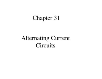
Phasor NotationThis diagram depicts a series RLCcircuit driven at a frequency thatcauses the inductive voltage to begreater than the capacitive voltage.This gives the circuit an overallinductive nature - the current (inphase with VR) is lagging the appliedvoltage Vapp.All of these voltage vectors (phasors) have a common timecomponent (ejωt) and so they all rotate at this common frequency.By suppressing this common rotation the concepts are easier tounderstand.MFMcGraw-PHY 2426Chap31-AC Circuits-Revised: 6/24/201264
RLC Circuit SolutiondI(t) 1 tRI(t) L I(t')dt' (t)dtC 0εI(t) I p e jωtThe solution of a differential equationbegins with the selection of a trial solutiondI jωI p e jωt jωI ;dtI I(t)dt jωMFMcGraw-PHY 2426IRI jωLI EjωC j R jωL I EωC 1 ER j ωL ωC I Chap31-AC Circuits-Revised: 6/24/201265
RLC Circuit Solution 1 ER j ωL ωC I 1 EZ R j ωL ωC I EZ IThe quantity Z is called the impedanceand it is a complex variableThese are complexvariablesE I Z is a complex version ofOhm’s LawMFMcGraw-PHY 2426Chap31-AC Circuits-Revised: 6/24/201266
Complex Impedance 1 Z R j ωL ωC z 1 z * z R ωL ωC ( )221ωL X L - XCωCtanθ RRMFMcGraw-PHY 2426Chap31-AC Circuits-Revised: 6/24/201267
Relative Voltage Phases - InductiveImpedance SpaceVoltage SpaceMFMcGraw-PHY 2426Chap31-AC Circuits-Revised: 6/24/201268
Phases in an Inductive AC CircuitRLC seriesL only seriesEarlier timeLater timeAll vectors rotating at acommon frequency ωIn an inductive circuit the voltage peaks first and thecurrent peaks later.MFMcGraw-PHY 2426Chap31-AC Circuits-Revised: 6/24/201269
Phases in a Capacitive AC CircuitRLC seriesC only seriesEarlier timeLater timeAll vectors rotating at acommon frequency ωIn capacitive circuit the current peaks first and thevoltage peaks later.MFMcGraw-PHY 2426Chap31-AC Circuits-Revised: 6/24/201270
RLC Series AC CircuitExampleMFMcGraw-PHY 2426Chap31-AC Circuits-Revised: 6/24/201271
R 250Ω, L 1.20mH,C 1.80µF, Vp 120v, f 60HzDetermine the following:(a.) XL - Inductive reactance(b.) XC - Capacitive reactance(c.) Z - Impedance(d.) θ - Phase angle(e.) Ip - Peak current(f.) IRMS - RMS current(g.) ωR - Resonance frequency(h.) Pavg - Average PowerMFMcGraw-PHY 2426Chap31-AC Circuits-Revised: 6/24/201272
R 250Ω, L 1.20mH,C 1.80µF, Vp 120v, f 60HzDetermine the following:(a.) XL - Inductive reactance(b.) XC - Capacitive reactance(c.) Z - ImpedanceFirst calc: ω 2πf 2(3.14)60 377 rad/sXL ωL 377(1.20x10⁻³) 0.452ΩXC 1/ωC 1/((377)(1.80x10-6)) 1474ΩZ R 2 (X L - X C )2 250 2 (0.452 - 1474)2Z 1495 ΩMFMcGraw-PHY 2426Chap31-AC Circuits-Revised: 6/24/201273
R 250Ω, L 1.20mH,C 1.80µF, Vp 120v, f 60HzDetermine the following:(d.) θ - Phase angleX L - XC -1 0.452 - 1474 -1 -1474 0θ tan tan tan -80.4 R250 250 -1MFMcGraw-PHY 2426Chap31-AC Circuits-Revised: 6/24/201274
R 250Ω, L 1.20mH,C 1.80µF, Vp 120v, f 60HzDetermine the following:(e.) Ip - Peak current(f.) IRMS - RMS current jωtV p j(ωt-θ)V Vpe j(ωt-θ)I e IepZZ p e jθZpVp120Ip 80.3mAZ14951st minus from the division.I I p e j(ωt-θ) 80.3mAe j(ωt 80.4)I RMS MFMcGraw-PHY 2426Ip2 0.707I p 56.7mAChap31-AC Circuits-Revised: 6/24/20122nd minus fromthe angle.75
R 250Ω, L 1.20mH,C 1.80µF, Vp 120v, f 60HzDetermine the following:(g.) ωR - Resonance frequencyωR 1 LC1(1.20x10 )(1.80x10 )-3-6 21.5krad/sω21.5x10 3f 3.42kHz2π6.28MFMcGraw-PHY 2426Chap31-AC Circuits-Revised: 6/24/201276
R 250Ω, L 1.20mH,C 1.80µF, Vp 120v, f 60HzDetermine the following:(h.) Pavg - Average Power1S VI * V V p e jωt I I p e j(ωt 80.4)211 jωt-j(ωt 80.4)S (V p e )( I p e V p I p e j(ωt-ωt-80.4))22V p I p -j(80.4)1-j(80.4)S Vp I pe e VRMS I RMS e -j(80.4)22 2MFMcGraw-PHY 2426Chap31-AC Circuits-Revised: 6/24/201277
Determine the following: (h.) Pavg - Average PowerV p I p -j(80.4)1-j(80.4)S Vp I pe e VRMS I RMS e -j(80.4)22 2S VRMS I RMS ( cos ( 80.4 ) - jsin ( 80.4 ) )S VRMS I RMS cos ( 80.4 ) - jVRMS I RMS sin ( 80.4 )Pavg VRMS I RMS cos ( 80.4 )Power FactorPavg 84.3 ( 56.7x10 -3 ) ( 0.167 ) 0.803WMFMcGraw-PHY 2426Chap31-AC Circuits-Revised: 6/24/201278
VoltagesVR I RMS R ( 56.7x10 -3 ) ( 250 ) 14.2VVL I RMS X L ( 56.7x10 -3 ) ( 377 ) ( 1.20x10 -3 ) 0.0265V()VC I RMS X C ( 56.7x10 -3 ) / 377 ( 1.80x10 -6 ) 83.6V222V VR (VL - VC ) ( 14.2 ) (0.0256 - 83.6)2V 84.8 VRMSMFMcGraw-PHY 2426Chap31-AC Circuits-Revised: 6/24/201279
Resonance in a Series RLC CircuitMFMcGraw-PHY 2426Chap31-AC Circuits-Revised: 6/24/201280
Resonance in a Series RLCCircuitMFMcGraw-PHY 2426Chap31-AC Circuits-Revised: 6/24/201281
Power Transfer and Resonanced 2QdQQL 2 R V p cosωtdtdtCZ R ( X L - XC )2Pavg I2RMSR V2pZ2RI I p cos ( ωt - δ ) 1 Z R ωL ωC V p22Pavg 2VpZcos ( ωt - δ )22R2222 ωL ω - ω0 1 2R ωMFMcGraw-PHY 2426Chap31-AC Circuits-Revised: 6/24/201282
Q Factor Measure of Stored EnergyV p2Pavg Q-FactorR2222 ωL ω - ω01 2 R ωω0f0EQ 2π E ω fE Total Energy and E is the dissipated energy ω FWHMFWHM Full Width at HalfMaximumAs an approximationω0 LQ RMFMcGraw-PHY 2426Chap31-AC Circuits-Revised: 6/24/201283
Resonance in a Series RLC CircuitMFMcGraw-PHY 2426Chap31-AC Circuits-Revised: 6/24/201284
RLC Parallel CircuitWe’re not covering this type of circuitMFMcGraw-PHY 2426Chap31-AC Circuits-Revised: 6/24/201285
Extra SlidesMFMcGraw-PHY 2426Chap31-AC Circuits-Revised: 6/24/201286
MFMcGraw-PHY 2426Chap31-AC Circuits-Revised: 6/24/201287
MFMcGraw-PHY 2426Chap31-AC Circuits-Revised: 6/24/201288
The average AC power is the product of the DC equivalent voltage and current. ( )( ) avg p p p p RMS RMS avg RMS RMS avg RMS RMS 1 P V I 2 V I since V and I 2 2 1 P 2 V 2 I 2 . Since there is a resistor in the circuit now there will be losses as the energy passes through the resisto