Transcription
74LCX00Low-voltage CMOS quad dual input NAND gate with5 V tolerant inputsDatasheet production dataFeatures 5 V tolerant inputs High speed– tPD 4.3 ns (max.) at VCC 3 V Power-down protection on inputs and outputs Symmetrical output impedance– IOH IOL 24 mA (min.) at VCC 3 V PCI bus levels guaranteed at 24 mA Balanced propagation delay– tPLH tPHL Operating voltage range– VCC (opr.) 2.0 V to 3.6 V Pin and function compatible with 74 series 00 Latch-up performance exceeds 500 mA(JESD 17) ESD performance– HBM: 2000 V (MIL STD 883 method 3015)– MM: 200 V– CDM: 1000 VApplications Automotive Industrial Computer ConsumerTable 1.SO-14TSSOP14DescriptionThe 74LCX00 device is a low-voltage CMOSquad dual input NAND gate manufactured withsub-micron silicon gate and double layer metalwiring C 2MOS technology. It is ideal for low-powerand high-speed 3.3 V applications and can beinterfaced to a 5 V signal environment for inputs.It has the same speed performance at 3.3 V asthe 5 V AC/ACT family, combined with lowerpower consumption.All inputs and outputs are equipped withprotection circuits against static discharge, givingthem 2 kV ESD immunity and transient excessvoltage.Device summaryOrder codeTemperature rangePackagePackagingMarking-40/ 85 CTSSOP14Tape and reelLCX00-40/ 85 CTSSOP14 (automotive grade)Tape and reelLCX00Y74LCX00MTR-40/ 85 CSO-14Tape and reel74LCX0074LCX00YMTR(1)-40/ 85 CSO-14 (automotive grade)Tape and reel74LCX00Y74LCX00TTR74LCX00YTTR(1)1. Qualification and characterization according to AEC Q100 and Q003 or equivalent, advanced screening according to AECQ001 and Q002 or equivalent.October 2012This is information on a product in full production.Doc ID 4972 Rev 71/16www.st.com16
Contents74LCX00Contents1Logic symbols and I/O equivalent circuit . . . . . . . . . . . . . . . . . . . . . . . . 32Pin settings . . . . . . . . . . . . . . . . . . . . . . . . . . . . . . . . . . . . . . . . . . . . . . . . 432.1Pin connections . . . . . . . . . . . . . . . . . . . . . . . . . . . . . . . . . . . . . . . . . . . . . 42.2Pin description . . . . . . . . . . . . . . . . . . . . . . . . . . . . . . . . . . . . . . . . . . . . . . 42.3Truth table . . . . . . . . . . . . . . . . . . . . . . . . . . . . . . . . . . . . . . . . . . . . . . . . . . 4Maximum ratings . . . . . . . . . . . . . . . . . . . . . . . . . . . . . . . . . . . . . . . . . . . . 5Recommended operating conditions . . . . . . . . . . . . . . . . . . . . . . . . . . . . . . . . . . . 54Electrical characteristics . . . . . . . . . . . . . . . . . . . . . . . . . . . . . . . . . . . . . 65Test circuit . . . . . . . . . . . . . . . . . . . . . . . . . . . . . . . . . . . . . . . . . . . . . . . . . 86Waveforms . . . . . . . . . . . . . . . . . . . . . . . . . . . . . . . . . . . . . . . . . . . . . . . . . 97Package mechanical data . . . . . . . . . . . . . . . . . . . . . . . . . . . . . . . . . . . . 108Revision history . . . . . . . . . . . . . . . . . . . . . . . . . . . . . . . . . . . . . . . . . . . 152/16Doc ID 4972 Rev 7
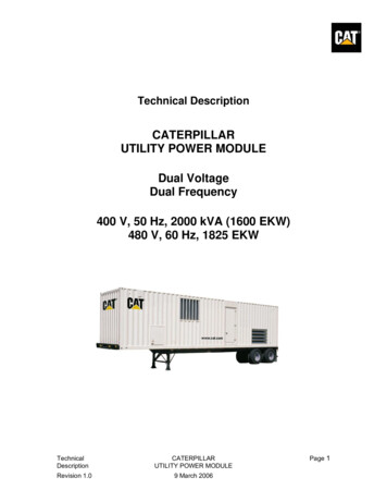
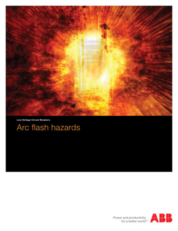
74LCX001Logic symbols and I/O equivalent circuitLogic symbols and I/O equivalent circuitFigure 1.IEC logic symbolsFigure 2.Input and output equivalent circuitDoc ID 4972 Rev 73/16
Pin settings74LCX002Pin settings2.1Pin connectionsFigure 3.2.2Pin descriptionTable 2.2.3Pin connections (top through view)Pin descriptionPin numberSymbolName and function1, 4, 9, 121A to 4AData inputs2, 5, 10, 131B to 4BData inputs3, 6, 8, 111Y to 4YData outputs7GNDGround (0 V)14VCCPositive supply voltageTruth tableTable 3.Truth tableInputs4/16OutputABYLLHLHHHLHHHLDoc ID 4972 Rev 7
74LCX003Maximum ratingsMaximum ratingsStressing the device above the rating listed in Table 4: Absolute maximum ratings maycause permanent damage to the device. These are stress ratings only and operation of thedevice at these or any other conditions above those indicated in Table 5: Recommendedoperating conditions of this specification is not implied. Exposure to absolute maximumrating conditions for extended periods may affect device reliability.Table 4.Absolute maximum ratingsSymbolParameterValueUnitSupply voltage-0.5 to 7.0VVIDC input voltage-0.5 to 7.0VVODC output voltage (VCC 0 V)-0.5 to 7.0V-0.5 to VCC 0.5VVCCstate)(1)VODC output voltage (high or lowIIKDC input diode current-50mAIOKDC output diode current(2)-50mAIODC output current 50mAICCDC supply current per supply pin 100mAIGNDDC ground current per supply pin 100mATstgStorage temperature-65 to 150 C300 CValueUnit2.0 to 3.6VTLLead temperature (10 sec.)1. IO absolute maximum rating must be observed.2. VO GND.Recommended operating conditionsTable 5.Recommended operating conditionsSymbolVCCParameterSupply voltage(1)VIInput voltage0 to 5.5VVOOutput voltage (VCC 0 V)0 to 5.5VVOOutput voltage (high or low state)0 to VCCVIOH, IOLHigh or low level output current (VCC 3.0 to 3.6 V) 24mAIOH, IOLHigh or low level output current (VCC 2.7 V) 12mA0 to 10ns/Vdt/dvInput rise and falltime(2)1. Truth table guaranteed: 1.5 V to 3.6 V.2. VIN from 0.8 V to 2 V at VCC 3.0 V.Doc ID 4972 Rev 75/16
Electrical characteristics474LCX00Electrical characteristicsTable 6.DC specificationsTest conditionSymbolVIHParameterValue-40 to 85 CVCC(V)Min.High level inputvoltageUnitMax.2.0V2.7 to 3.6VILVOHLow level inputvoltageHigh level outputvoltage0.82.7 to 3.6IO -100 μAVCC - 0.22.7IO -12 mA2.2IO -18 mA2.4IO -24 mA2.2VV3.0VOLLow level outputvoltage2.7 to 3.6IO 100 μA0.22.7IO 12 mA0.4IO 16 mA0.4IO 24 mA0.55VI 0 to 5.5 V 5μAVI or VO 5.5 V10μAVI VCC or GND10VI or VO 3.6 to 5.5 V 10VIH VCC - 0.6 V500V3.0IIInput leakage current 2.7 to 3.6IoffPower OFF leakagecurrentICCQuiescent supplycurrent2.7 to 3.6ΔICCICC incr. per input2.7 to 3.6Table 7.0VOLPVOLVParameterDynamic low levelquiet output (1)TA 25 CVCC(V)3.3ValueMin.CL 50 pFVIL 0 V, VIH 3.3 VTyp.Doc ID 4972 Rev 7UnitMax.0.8V-0.81. Number of outputs defined as “n”. Measured with “n-1” outputs switching from HIGH to LOW or LOW toHIGH. The remaining output is measured in the LOW state.6/16μADynamic switching characteristicsTest conditionSymbolμA
74LCX00Electrical characteristicsTable 8.AC electrical characteristicsTest conditionSymboltPLH tPHLtOSLHtOSHLParameterPropagation delaytimeOutput-to-outputskew time(1), (2)VCC(V)ValueCL(pF)RL(Ω)ts tr(ns)505002.5-40 to 85 CMin.2.7UnitMax.5.13.0 to 3.63.0 to 3.6ns1.0505002.54.31.0ns1. Skew is defined as the absolute value of the difference between the actual propagation delay for any twooutputs of the same device switching in the same direction, either HIGH or LOW (tOSLH tPLHm - tPLHn ,tOSHL tPHLm - tPHLn ).2. Parameter guaranteed by design.Table 9.Capacitive characteristicsTest conditionSymbolC INCPD1.ParameterInput capacitancePower dissipationcapacitance(1)ValueTA 25 CVCC(V)Min.Typ.UnitMax.3.3VIN 0 to VCC6pF3.3fIN 10 MHzVIN 0 or VCC35pFCPD is defined as the value of the IC’s internal equivalent capacitance which is calculated from theoperating current consumption without load. (Refer to Section 5: Test circuit). Average operating currentcan be obtained by the following equation. ICC(opr) CPD x VCC x fIN ICC/4 (per gate).Doc ID 4972 Rev 77/16
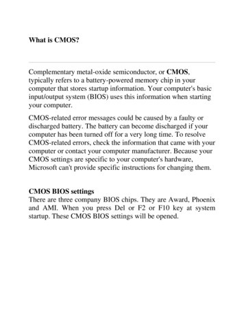
Test circuit574LCX00Test circuitFigure 4.Note:Test circuitCL 50 pF or equivalent (includes jig and probe capacitance)RL 500 Ω or equivalentRT ZOUT of pulse generator (typically 50 Ω ).8/16Doc ID 4972 Rev 7
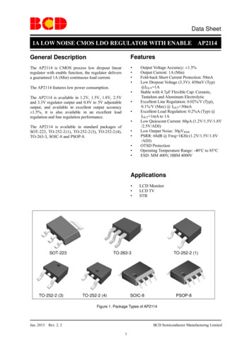
74LCX006WaveformsWaveformsFigure 5.Waveform - propagation delay (f 1 MHz; 50% duty cycle)Doc ID 4972 Rev 79/16
Package mechanical data774LCX00Package mechanical dataIn order to meet environmental requirements, ST offers these devices in different grades ofECOPACK packages, depending on their level of environmental compliance. ECOPACKspecifications, grade definitions and product status are available at: www.st.com. ECOPACKis an ST trademark.10/16Doc ID 4972 Rev 7
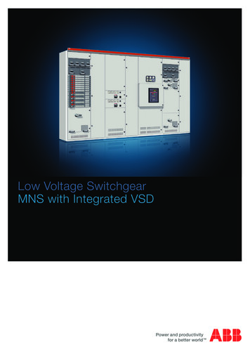
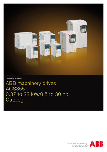
74LCX00Package mechanical dataFigure 6.SO-14 package outlineTable 10.SO-14 package mechanical .2280.244h0.250.500.0100.020L0.41.270.0160.050k0 8 0 8 ddd0.100Doc ID 4972 Rev 70.00411/16
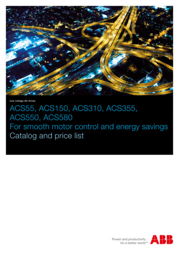
Package mechanical data74LCX00Figure 7.TSSOP14 package outlineTable 11.TSSOP14 package mechanical .480.1690.1730.176e12/16inch10.65 BSCK0 L0.450.600.0256 BSC8 0 0.750.018Doc ID 4972 Rev 78 0.0240.030
74LCX00Package mechanical dataFigure 8.Tape and reel SO-14 outline1. Drawing is not in scale.Table 12.Tape and reel SO-14 mechanical .0820.090Po3.94.10.1530.161P7.98.10.3110.319Doc ID 4972 Rev 713/16
Package mechanical dataFigure 9.74LCX00Tape and reel TSSOP14 outlineDrawing is not in scale.Table 13.Tape and reel TSSOP14 mechanical 9Doc ID 4972 Rev 7
74LCX008Revision historyRevision historyTable 14.Document revision historyDateRevision15-Sep-20044Ordering code revision - pag 107-Jul-20065New template, temperature ranges updated6Added Applications on page 1Updated Table 1: Device summary on page 1Updated Top in Table 5: Recommended operating conditionsUpdated ECOPACK text in Section 7: Package mechanical dataMinor textual updates7Updated ESD performance in Features (updated HBM and MM,added CDM).Added 74LCX00YMTR device and “Marking” to Table 1, updatedtemperature range, note 1.Updated Section 3: Maximum ratings (added cross-references).Removed “Operating temperature” from Table 5.Reformatted Section 7: Package mechanical data.Minor corrections throughout document.20-Jun-201202-Oct-2012ChangesDoc ID 4972 Rev 715/16
74LCX00Please Read Carefully:Information in this document is provided solely in connection with ST products. STMicroelectronics NV and its subsidiaries (“ST”) reserve theright to make changes, corrections, modifications or improvements, to this document, and the products and services described herein at anytime, without notice.All ST products are sold pursuant to ST’s terms and conditions of sale.Purchasers are solely responsible for the choice, selection and use of the ST products and services described herein, and ST assumes noliability whatsoever relating to the choice, selection or use of the ST products and services described herein.No license, express or implied, by estoppel or otherwise, to any intellectual property rights is granted under this document. If any part of thisdocument refers to any third party products or services it shall not be deemed a license grant by ST for the use of such third party productsor services, or any intellectual property contained therein or considered as a warranty covering the use in any manner whatsoever of suchthird party products or services or any intellectual property contained therein.UNLESS OTHERWISE SET FORTH IN ST’S TERMS AND CONDITIONS OF SALE ST DISCLAIMS ANY EXPRESS OR IMPLIEDWARRANTY WITH RESPECT TO THE USE AND/OR SALE OF ST PRODUCTS INCLUDING WITHOUT LIMITATION IMPLIEDWARRANTIES OF MERCHANTABILITY, FITNESS FOR A PARTICULAR PURPOSE (AND THEIR EQUIVALENTS UNDER THE LAWSOF ANY JURISDICTION), OR INFRINGEMENT OF ANY PATENT, COPYRIGHT OR OTHER INTELLECTUAL PROPERTY RIGHT.UNLESS EXPRESSLY APPROVED IN WRITING BY TWO AUTHORIZED ST REPRESENTATIVES, ST PRODUCTS ARE NOTRECOMMENDED, AUTHORIZED OR WARRANTED FOR USE IN MILITARY, AIR CRAFT, SPACE, LIFE SAVING, OR LIFE SUSTAININGAPPLICATIONS, NOR IN PRODUCTS OR SYSTEMS WHERE FAILURE OR MALFUNCTION MAY RESULT IN PERSONAL INJURY,DEATH, OR SEVERE PROPERTY OR ENVIRONMENTAL DAMAGE. ST PRODUCTS WHICH ARE NOT SPECIFIED AS "AUTOMOTIVEGRADE" MAY ONLY BE USED IN AUTOMOTIVE APPLICATIONS AT USER’S OWN RISK.Resale of ST products with provisions different from the statements and/or technical features set forth in this document shall immediately voidany warranty granted by ST for the ST product or service described herein and shall not create or extend in any manner whatsoever, anyliability of ST.ST and the ST logo are trademarks or registered trademarks of ST in various countries.Information in this document supersedes and replaces all information previously supplied.The ST logo is a registered trademark of STMicroelectronics. All other names are the property of their respective owners. 2012 STMicroelectronics - All rights reservedSTMicroelectronics group of companiesAustralia - Belgium - Brazil - Canada - China - Czech Republic - Finland - France - Germany - Hong Kong - India - Israel - Italy - Japan Malaysia - Malta - Morocco - Philippines - Singapore - Spain - Sweden - Switzerland - United Kingdom - United States of Americawww.st.com16/16Doc ID 4972 Rev 7
Datasheet production data Features 5 V tolerant inputs High speed –tPD 4.3 ns (max.) at VCC 3 V Power-down protection on inputs and outputs Symmetrical output impedance – IOH IOL 24 mA (min.) at VCC 3 V PCI bus levels guaranteed at 24 mA Balanced propagation delay –tPLH tPHL Operating voltage range –VCC (opr.) 2.0 V to 3.6 V Pin and function compatible with 74 .